2009 CHERY TIGGO clutch
[x] Cancel search: clutchPage 1265 of 1903
Downloaded from www.Manualslib.com manuals search engine Clutch Master Cylinder
Description
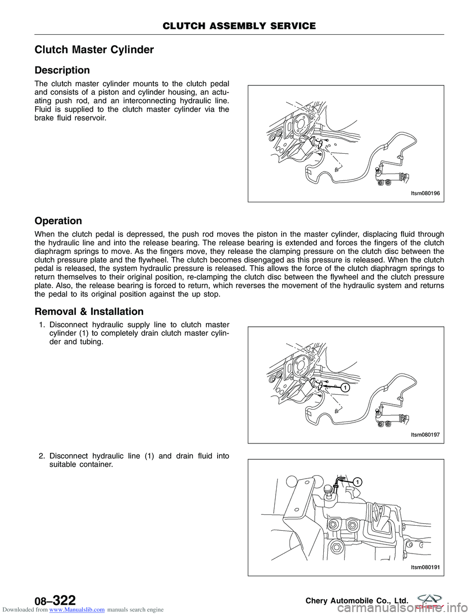
The clutch master cylinder mounts to the clutch pedal
and consists of a piston and cylinder housing, an actu-
ating push rod, and an interconnecting hydraulic line.
Fluid is supplied to the clutch master cylinder via the
brake fluid reservoir.
Operation
When the clutch pedal is depressed, the push rod moves the piston in the master cylinder, displacing fluid through
the hydraulic line and into the release bearing. The release bearing is extended and forces the fingers of the clutch
diaphragm springs to move. As the fingers move, they release the clamping pressure on the clutch disc between the
clutch pressure plate and the flywheel. The clutch becomes disengaged as this pressure is released. When the clutch
pedal is released, the system hydraulic pressure is released. This allows the force of the clutch diaphragm springs to
return themselves to their original position, re-clamping the clutch disc between the flywheel and the clutch pressure
plate. Also, the release bearing is forced to return, which reverses the movement of the hydraulic system and returns
the pedal to its original position against the up stop.
Removal & Installation
1. Disconnect hydraulic supply line to clutch mastercylinder (1) to completely drain clutch master cylin-
der and tubing.
2. Disconnect hydraulic line (1) and drain fluid into suitable container.
CLUTCH ASSEMBLY SERVICE
LTSM080196
LTSM080197
LTSM080191
08–322Chery Automobile Co., Ltd.
Page 1266 of 1903
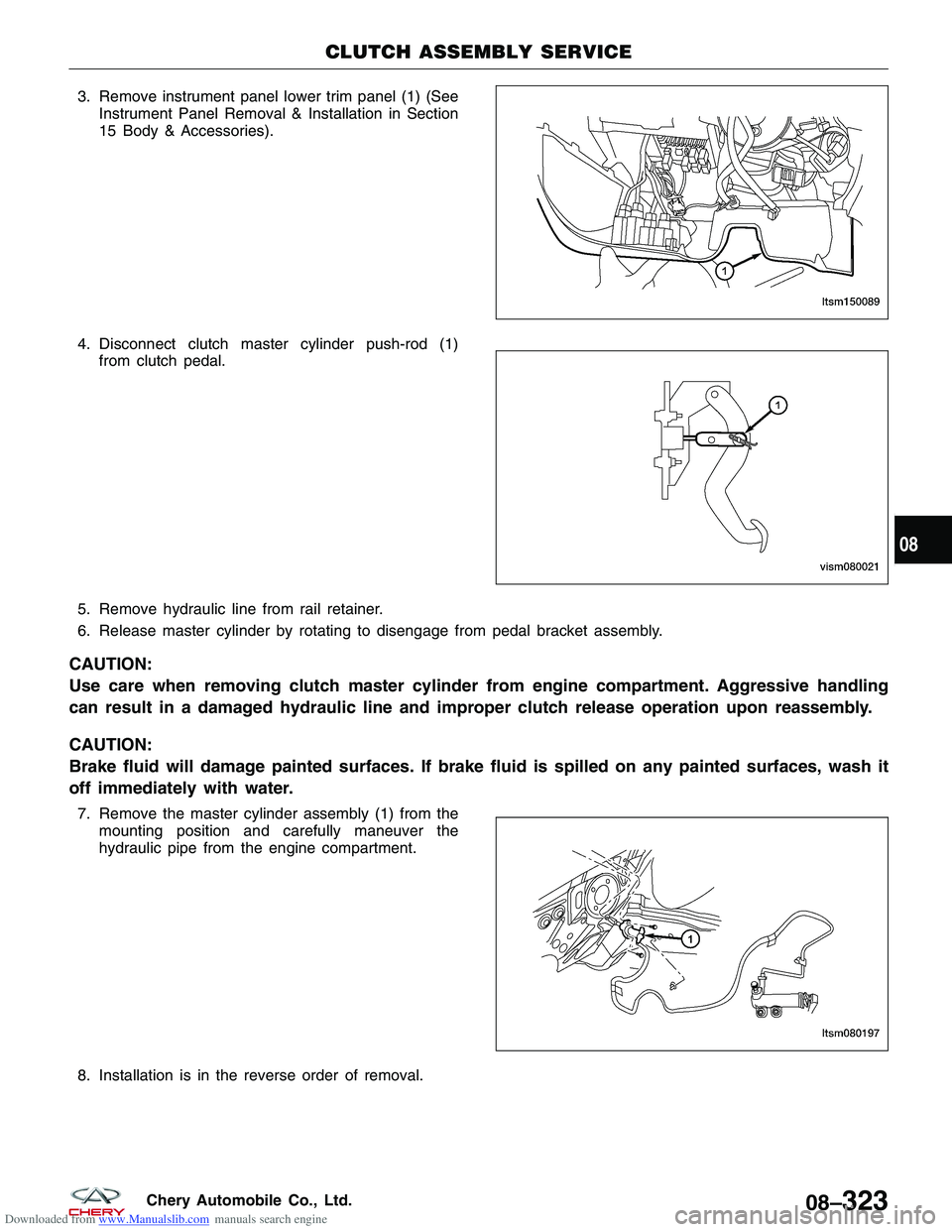
Downloaded from www.Manualslib.com manuals search engine 3. Remove instrument panel lower trim panel (1) (SeeInstrument Panel Removal & Installation in Section
15 Body & Accessories).
4. Disconnect clutch master cylinder push-rod (1) from clutch pedal.
5. Remove hydraulic line from rail retainer.
6. Release master cylinder by rotating to disengage from pedal bracket assembly.
CAUTION:
Use care when removing clutch master cylinder from engine compartment. Aggressive handling
can result in a damaged hydraulic line and improper clutch release operation upon reassembly.
CAUTION:
Brake fluid will damage painted surfaces. If brake fluid is spilled on any painted surfaces, wash it
off immediately with water.
7. Remove the master cylinder assembly (1) from the mounting position and carefully maneuver the
hydraulic pipe from the engine compartment.
8. Installation is in the reverse order of removal.
CLUTCH ASSEMBLY SERVICE
LTSM150089
VISM080021
LTSM080197
08
08–323Chery Automobile Co., Ltd.
Page 1267 of 1903
Downloaded from www.Manualslib.com manuals search engine Clutch Slave Cylinder
Removal & Installation
NOTE :
After replacing the slave cylinder, it is necessary to make sure brake master cylinder fluid level is full and the res-
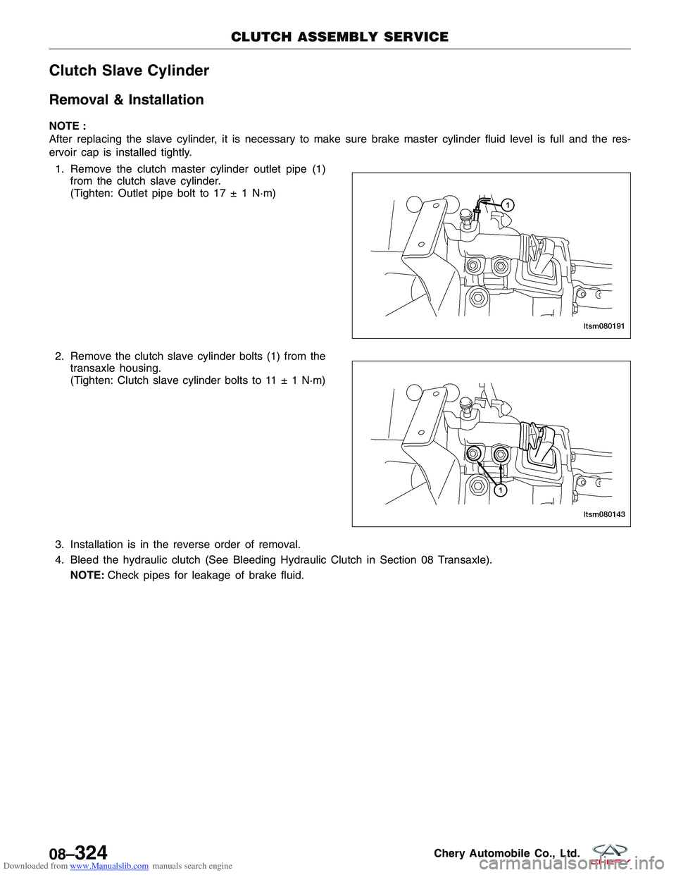
ervoir cap is installed tightly.1. Remove the clutch master cylinder outlet pipe (1) from the clutch slave cylinder.
(Tighten: Outlet pipe bolt to 17 ± 1 N·m)
2. Remove the clutch slave cylinder bolts (1) from the transaxle housing.
(Tighten: Clutch slave cylinder bolts to 11 ± 1 N·m)
3. Installation is in the reverse order of removal.
4. Bleed the hydraulic clutch (See Bleeding Hydraulic Clutch in Section 08 Transaxle). NOTE: Check pipes for leakage of brake fluid.
CLUTCH ASSEMBLY SERVICE
LTSM080191
LTSM080143
08–324Chery Automobile Co., Ltd.
Page 1268 of 1903
Downloaded from www.Manualslib.com manuals search engine Bleeding Hydraulic Clutch
Operation
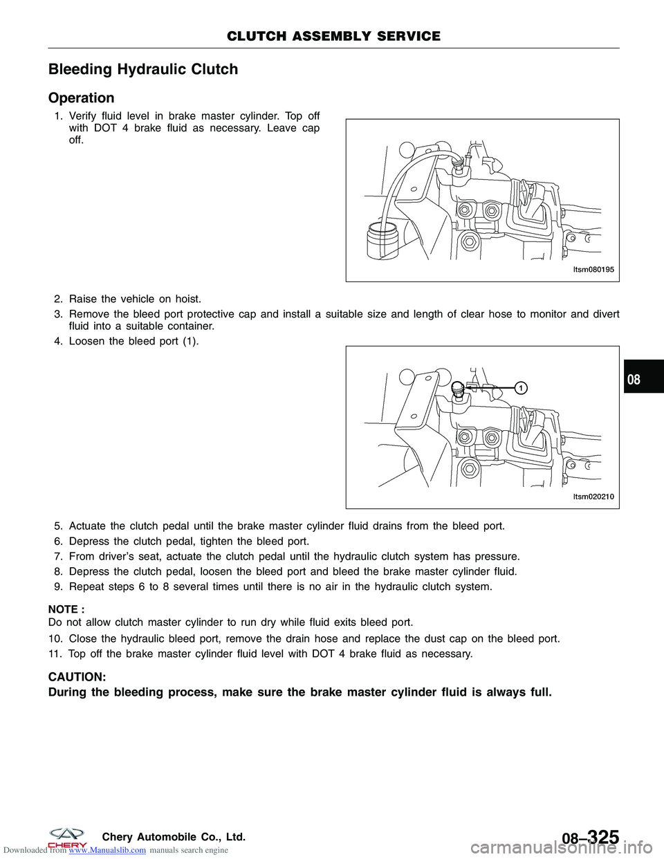
1. Verify fluid level in brake master cylinder. Top offwith DOT 4 brake fluid as necessary. Leave cap
off.
2. Raise the vehicle on hoist.
3. Remove the bleed port protective cap and install a suitable size and length of clear hose to monitor and divert fluid into a suitable container.
4. Loosen the bleed port (1).
5. Actuate the clutch pedal until the brake master cylinder fluid drains from the bleed port.
6. Depress the clutch pedal, tighten the bleed port.
7. From driver’s seat, actuate the clutch pedal until the hydraulic clutch system has pressure.
8. Depress the clutch pedal, loosen the bleed port and bleed the brake master cylinder fluid.
9. Repeat steps 6 to 8 several times until there is no air in the hydraulic clutch system.
NOTE :
Do not allow clutch master cylinder to run dry while fluid exits bleed port.
10. Close the hydraulic bleed port, remove the drain hose and replace the dust cap on the bleed port.
11. Top off the brake master cylinder fluid level with DOT 4 brake fluid as necessary.
CAUTION:
During the bleeding process, make sure the brake master cylinder fluid is always full.
CLUTCH ASSEMBLY SERVICE
LTSM080195
LTSM020210
08
08–325Chery Automobile Co., Ltd.
Page 1273 of 1903
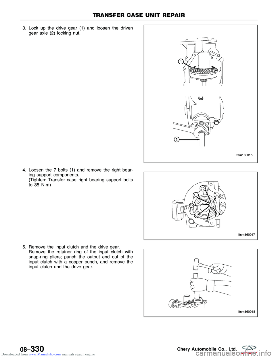
Downloaded from www.Manualslib.com manuals search engine 3. Lock up the drive gear (1) and loosen the drivengear axle (2) locking nut.
4. Loosen the 7 bolts (1) and remove the right bear- ing support components.
(Tighten: Transfer case right bearing support bolts
to 35 N·m)
5. Remove the input clutch and the drive gear. Remove the retainer ring of the input clutch with
snap-ring pliers; punch the output end out of the
input clutch with a copper punch, and remove the
input clutch and the drive gear.
TRANSFER CASE UNIT REPAIR
LTSM160015
LTSM160017
LTSM160018
08–330Chery Automobile Co., Ltd.
Page 1274 of 1903
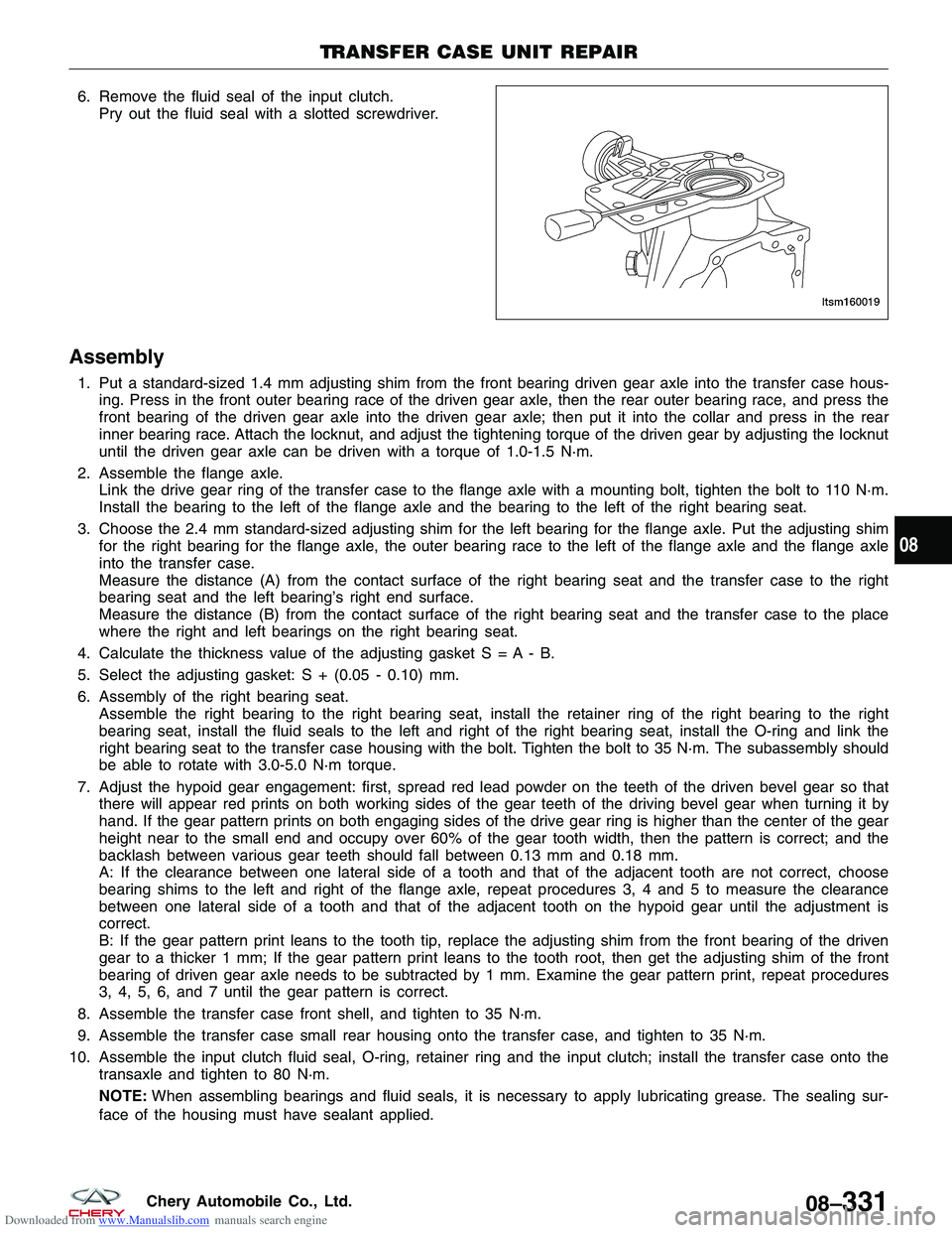
Downloaded from www.Manualslib.com manuals search engine 6. Remove the fluid seal of the input clutch.Pry out the fluid seal with a slotted screwdriver.
Assembly
1. Put a standard-sized 1.4 mm adjusting shim from the front bearing driven gear axle into the transfer case hous-ing. Press in the front outer bearing race of the driven gear axle, then the rear outer bearing race, and press the
front bearing of the driven gear axle into the driven gear axle; then put it into the collar and press in the rear
inner bearing race. Attach the locknut, and adjust the tightening torque of the driven gear by adjusting the locknut
until the driven gear axle can be driven with a torque of 1.0-1.5 N·m.
2. Assemble the flange axle. Link the drive gear ring of the transfer case to the flange axle with a mounting bolt, tighten the bolt to 110 N·m.
Install the bearing to the left of the flange axle and the bearing to the left of the right bearing seat.
3. Choose the 2.4 mm standard-sized adjusting shim for the left bearing for the flange axle. Put the adjusting shim for the right bearing for the flange axle, the outer bearing race to the left of the flange axle and the flange axle
into the transfer case.
Measure the distance (A) from the contact surface of the right bearing seat and the transfer case to the right
bearing seat and the left bearing’s right end surface.
Measure the distance (B) from the contact surface of the right bearing seat and the transfer case to the place
where the right and left bearings on the right bearing seat.
4. Calculate the thickness value of the adjusting gasket S = A - B.
5. Select the adjusting gasket: S + (0.05 - 0.10) mm.
6. Assembly of the right bearing seat. Assemble the right bearing to the right bearing seat, install the retainer ring of the right bearing to the right
bearing seat, install the fluid seals to the left and right of the right bearing seat, install the O-ring and link the
right bearing seat to the transfer case housing with the bolt. Tighten the bolt to 35 N·m. The subassembly should
be able to rotate with 3.0-5.0 N·m torque.
7. Adjust the hypoid gear engagement: first, spread red lead powder on the teeth of the driven bevel gear so that there will appear red prints on both working sides of the gear teeth of the driving bevel gear when turning it by
hand. If the gear pattern prints on both engaging sides of the drive gear ring is higher than the center of the gear
height near to the small end and occupy over 60% of the gear tooth width, then the pattern is correct; and the
backlash between various gear teeth should fall between 0.13 mm and 0.18 mm.
A: If the clearance between one lateral side of a tooth and that of the adjacent tooth are not correct, choose
bearing shims to the left and right of the flange axle, repeat procedures 3, 4 and 5 to measure the clearance
between one lateral side of a tooth and that of the adjacent tooth on the hypoid gear until the adjustment is
correct.
B: If the gear pattern print leans to the tooth tip, replace the adjusting shim from the front bearing of the driven
gear to a thicker 1 mm; If the gear pattern print leans to the tooth root, then get the adjusting shim of the front
bearing of driven gear axle needs to be subtracted by 1 mm. Examine the gear pattern print, repeat procedures
3, 4, 5, 6, and 7 until the gear pattern is correct.
8. Assemble the transfer case front shell, and tighten to 35 N·m.
9. Assemble the transfer case small rear housing onto the transfer case, and tighten to 35 N·m.
10. Assemble the input clutch fluid seal, O-ring, retainer ring and the input clutch; install the transfer case onto the transaxle and tighten to 80 N·m.
NOTE: When assembling bearings and fluid seals, it is necessary to apply lubricating grease. The sealing sur-
face of the housing must have sealant applied.
TRANSFER CASE UNIT REPAIR
LTSM160019
08
08–331Chery Automobile Co., Ltd.
Page 1292 of 1903
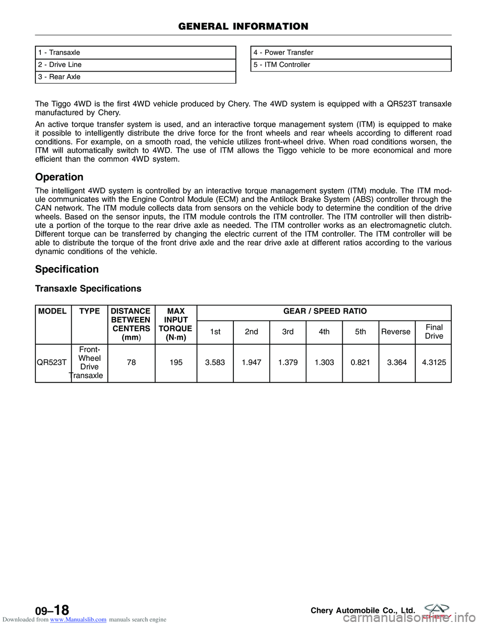
Downloaded from www.Manualslib.com manuals search engine The Tiggo 4WD is the first 4WD vehicle produced by Chery. The 4WD system is equipped with a QR523T transaxle
manufactured by Chery.
An active torque transfer system is used, and an interactive torque management system (ITM) is equipped to make
it possible to intelligently distribute the drive force for the front wheels and rear wheels according to different road
conditions. For example, on a smooth road, the vehicle utilizes front-wheel drive. When road conditions worsen, the
ITM will automatically switch to 4WD. The use of ITM allows the Tiggo vehicle to be more economical and more
efficient than the common 4WD system.
Operation
The intelligent 4WD system is controlled by an interactive torque management system (ITM) module. The ITM mod-
ule communicates with the Engine Control Module (ECM) and the Antilock Brake System (ABS) controller through the
CAN network. The ITM module collects data from sensors on the vehicle body to determine the condition of the drive
wheels. Based on the sensor inputs, the ITM module controls the ITM controller. The ITM controller will then distrib-
ute a portion of the torque to the rear drive axle as needed. The ITM controller works as an electromagnetic clutch.
Different torque can be transferred by changing the electric current of the ITM controller. The ITM controller will be
able to distribute the torque of the front drive axle and the rear drive axle at different ratios according to the various
dynamic conditions of the vehicle.
Specification
Transaxle Specifications
MODEL TYPE DISTANCEBETWEENCENTERS (mm) MAX
INPUT
TORQUE (N·m) GEAR / SPEED RATIO
1st 2nd 3rd 4th 5th Reverse Final
Drive
QR523T Front-
Wheel Drive
Transaxle 78 195 3.583 1.947 1.379 1.303 0.821 3.364 4.3125
1 - Transaxle
2 - Drive Line
3 - Rear Axle4 - Power Transfer
5 - ITM Controller
GENERAL INFORMATION
LTSM160027
09–18Chery Automobile Co., Ltd.
Page 1406 of 1903
Downloaded from www.Manualslib.com manuals search engine 6. Check the brake pedal travel. If pedal travel is excessive or has not been improved, some air may still betrapped in the system. Re-bleed the brakes as necessary.
7. Test drive the vehicle to verify the brakes are operating properly and pedal feel is correct.
Master Cylinder - LHD
Description
The master cylinder body is an anodized aluminum casting. It is located at the left side of the engine room. It has a
machined bore to accept the master cylinder pistons and also has threaded ports with seats for hydraulic brake tube
connections. The master cylinder has the brake fluid reservoir mounted on top of it and supplies brake fluid to the
master cylinder as required. On manual transaxle equipped vehicles, the brake fluid reservoir also feeds the clutch
hydraulic circuit. The reservoir is made of clear plastic and it houses the brake fluid level switch.
Operation
When the brake pedal is pressed, the master cylinder pistons apply brake pressure through the chassis brake tubes
to each brake assembly. The brake fluid reservoir supplies the brake hydraulic system with the necessary fluid to
operate properly.
Removal & Installation
CAUTION:
The vacuum in the power brake booster must be pumped down before removing the master cyl-
inder to avoid damaging the master cylinder and to prevent the booster from sucking in any con-
tamination. This can be done by pumping the brake pedal while the engine is not running until a
firm brake pedal is achieved.
1. Turn the ignition switch off.
2. Siphon out as much brake fluid as possible from the master cylinder.
3. With the engine off, pump the brake pedal 4-5 strokes until the pedal feel is firm.
4. Disconnect the negative battery cable.
5. Disconnect the brake fluid level switch electrical connector in the master cylinder brake fluid reservoir.
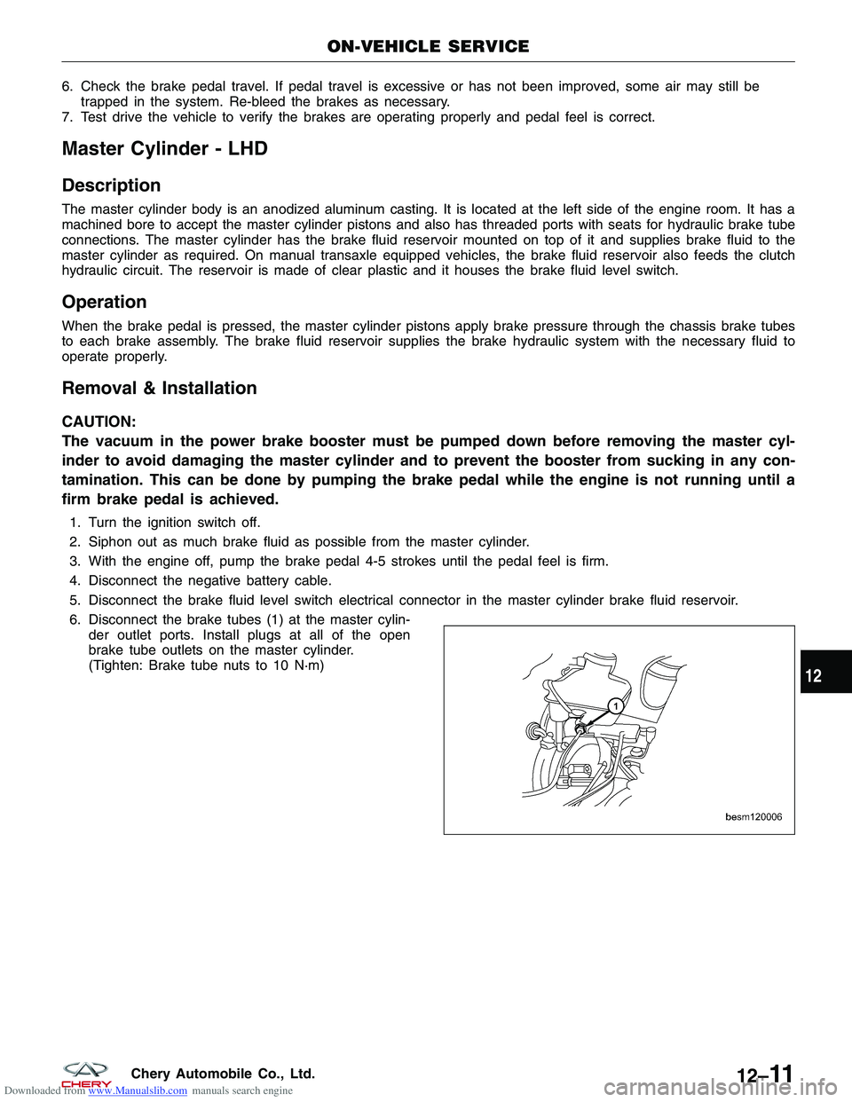
6. Disconnect the brake tubes (1) at the master cylin- der outlet ports. Install plugs at all of the open
brake tube outlets on the master cylinder.
(Tighten: Brake tube nuts to 10 N·m)
ON-VEHICLE SERVICE
BESM120006
12
12–11Chery Automobile Co., Ltd.