Page 1355 of 1903

Downloaded from www.Manualslib.com manuals search engine Non-Directional Tires
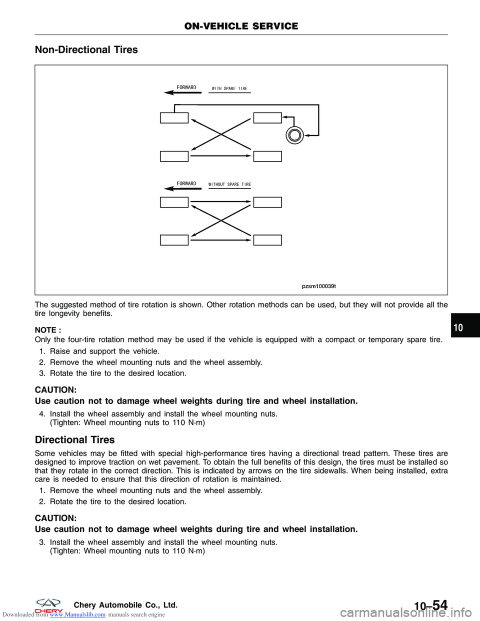
The suggested method of tire rotation is shown. Other rotation methods can be used, but they will not provide all the
tire longevity benefits.
NOTE :
Only the four-tire rotation method may be used if the vehicle is equipped with a compact or temporary spare tire.1. Raise and support the vehicle.
2. Remove the wheel mounting nuts and the wheel assembly.
3. Rotate the tire to the desired location.
CAUTION:
Use caution not to damage wheel weights during tire and wheel installation.
4. Install the wheel assembly and install the wheel mounting nuts. (Tighten: Wheel mounting nuts to 110 N·m)
Directional Tires
Some vehicles may be fitted with special high-performance tires having a directional tread pattern. These tires are
designed to improve traction on wet pavement. To obtain the full benefits of this design, the tires must be installed so
that they rotate in the correct direction. This is indicated by arrows on the tire sidewalls. When being installed, extra
care is needed to ensure that this direction of rotation is maintained.
1. Remove the wheel mounting nuts and the wheel assembly.
2. Rotate the tire to the desired location.
CAUTION:
Use caution not to damage wheel weights during tire and wheel installation.
3. Install the wheel assembly and install the wheel mounting nuts. (Tighten: Wheel mounting nuts to 110 N·m)
ON-VEHICLE SERVICE
PZSM100039T
10
10–54Chery Automobile Co., Ltd.
Page 1357 of 1903

Downloaded from www.Manualslib.com manuals search engine GENERAL INFORMATION
Description
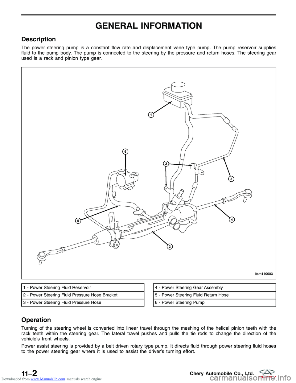
The power steering pump is a constant flow rate and displacement vane type pump. The pump reservoir supplies
fluid to the pump body. The pump is connected to the steering by the pressure and return hoses. The steering gear
used is a rack and pinion type gear.
Operation
Turning of the steering wheel is converted into linear travel through the meshing of the helical pinion teeth with the
rack teeth within the steering gear. The lateral travel pushes and pulls the tie rods to change the direction of the
vehicle’s front wheels.
Power assist steering is provided by a belt driven rotary type pump. It directs fluid through power steering fluid hoses
to the power steering gear where it is used to assist the driver’s turning effort.
1 - Power Steering Fluid Reservoir
2 - Power Steering Fluid Pressure Hose Bracket
3 - Power Steering Fluid Pressure Hose4 - Power Steering Gear Assembly
5 - Power Steering Fluid Return Hose
6 - Power Steering Pump
LTSM110003
11 –2Chery Automobile Co., Ltd.
Page 1358 of 1903
Downloaded from www.Manualslib.com manuals search engine Manual steering control of the vehicle can be maintained if power steering assist is lost. However, under this condi-
tion, steering effort is significantly increased.
WARNING!
Power steering fluid, engine parts and exhaust system may be extremely hot if engine has been running. Do not
start engine with any loose or disconnected hoses. Do not allow hoses to touch hot exhaust manifold or cata-
lyst. Fluid level should be checked with the engine off to prevent personal injury from moving parts.
Specifications
Fluid Specifications
DESCRIPTIONCAPACITY (L)
Power Steering Fluid (ATF III) 1.1
Special Tools
Steering Wheel Puller
Ball Joint Separator
CH-10002
GENERAL INFORMATION
11
11 –3Chery Automobile Co., Ltd.
Page 1359 of 1903

Downloaded from www.Manualslib.com manuals search engine DIAGNOSIS & TESTING
Power Steering Troubleshooting Chart
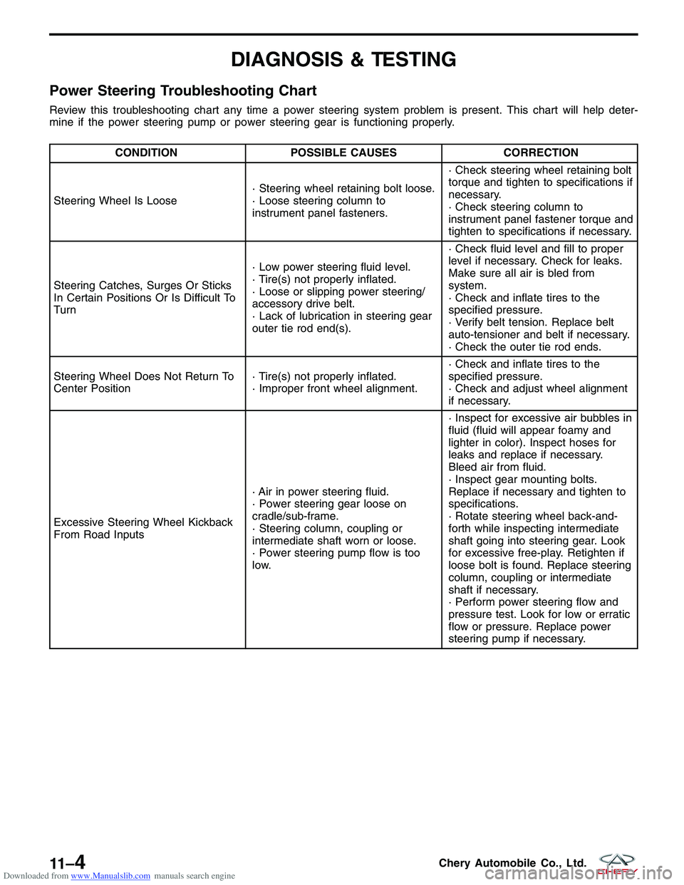
Review this troubleshooting chart any time a power steering system problem is present. This chart will help deter-
mine if the power steering pump or power steering gear is functioning properly.
CONDITIONPOSSIBLE CAUSES CORRECTION
Steering Wheel Is Loose · Steering wheel retaining bolt loose.
· Loose steering column to
instrument panel fasteners.· Check steering wheel retaining bolt
torque and tighten to specifications if
necessary.
· Check steering column to
instrument panel fastener torque and
tighten to specifications if necessary.
Steering Catches, Surges Or Sticks
In Certain Positions Or Is Difficult To
Turn · Low power steering fluid level.
· Tire(s) not properly inflated.
· Loose or slipping power steering/
accessory drive belt.
· Lack of lubrication in steering gear
outer tie rod end(s).· Check fluid level and fill to proper
level if necessary. Check for leaks.
Make sure all air is bled from
system.
· Check and inflate tires to the
specified pressure.
· Verify belt tension. Replace belt
auto-tensioner and belt if necessary.
· Check the outer tie rod ends.
Steering Wheel Does Not Return To
Center Position · Tire(s) not properly inflated.
· Improper front wheel alignment.· Check and inflate tires to the
specified pressure.
· Check and adjust wheel alignment
if necessary.
Excessive Steering Wheel Kickback
From Road Inputs · Air in power steering fluid.
· Power steering gear loose on
cradle/sub-frame.
· Steering column, coupling or
intermediate shaft worn or loose.
· Power steering pump flow is too
low.· Inspect for excessive air bubbles in
fluid (fluid will appear foamy and
lighter in color). Inspect hoses for
leaks and replace if necessary.
Bleed air from fluid.
· Inspect gear mounting bolts.
Replace if necessary and tighten to
specifications.
· Rotate steering wheel back-and-
forth while inspecting intermediate
shaft going into steering gear. Look
for excessive free-play. Retighten if
loose bolt is found. Replace steering
column, coupling or intermediate
shaft if necessary.
· Perform power steering flow and
pressure test. Look for low or erratic
flow or pressure. Replace power
steering pump if necessary.
11 –4Chery Automobile Co., Ltd.
Page 1362 of 1903

Downloaded from www.Manualslib.com manuals search engine Inspection
1. If the power steering fluid level is low, inspect the entire power steering system for potential leaks.
CAUTION:
DO NOT operate the vehicle with foamy steering fluid for an extended period. This may cause
pump damage.
2. Perform the following to inspect the power steering fluid reservoir level:•Park the vehicle on a level surface.
• Start the engine.
• Turn the steering wheel several times to heat the power steering fluid to 50°- 60°C.
• With the engine running, turn the steering wheel left and right to the wheel stops and repeat this several
times.
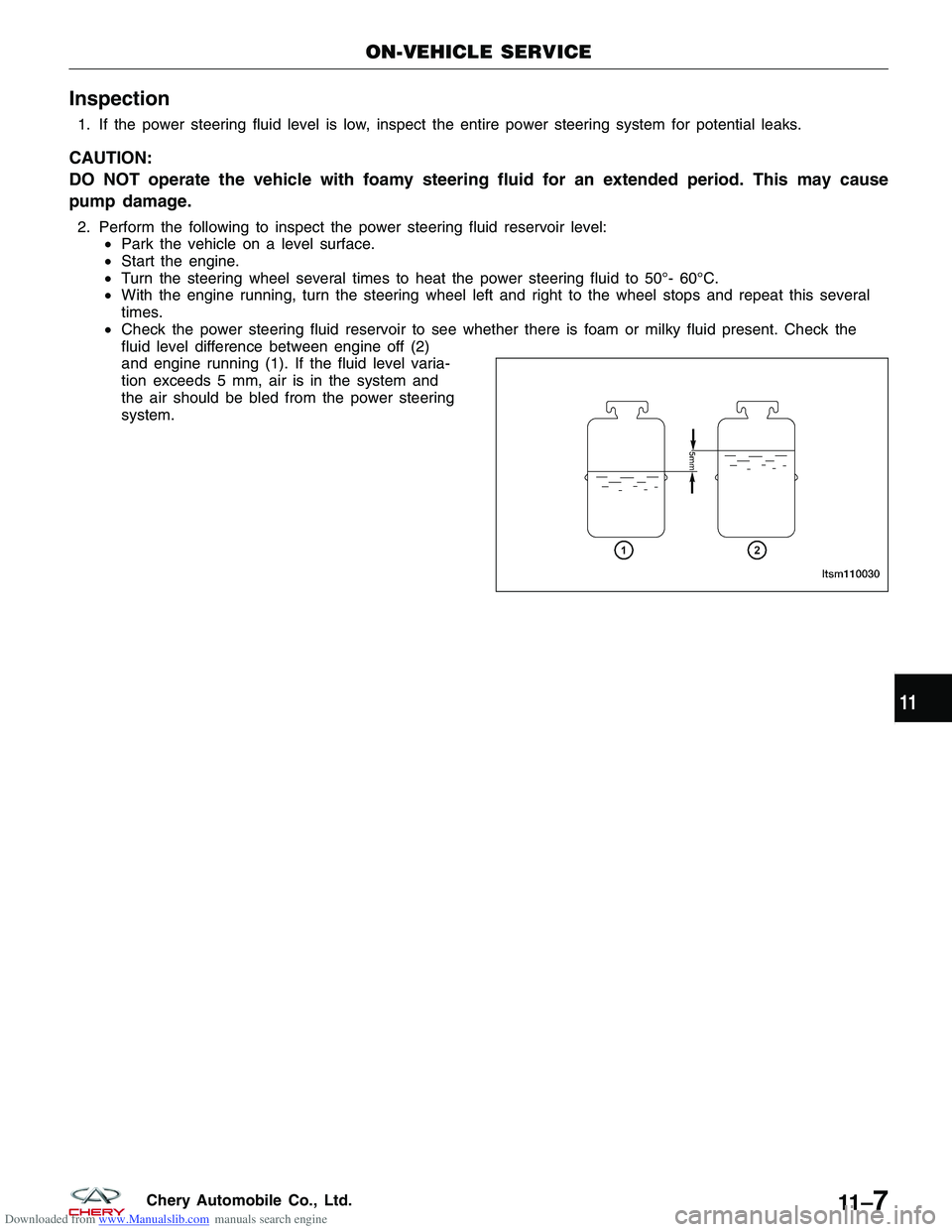
• Check the power steering fluid reservoir to see whether there is foam or milky fluid present. Check the
fluid level difference between engine off (2)
and engine running (1). If the fluid level varia-
tion exceeds 5 mm, air is in the system and
the air should be bled from the power steering
system.
ON-VEHICLE SERVICE
LTSM110030
11
11 –7Chery Automobile Co., Ltd.
Page 1363 of 1903
Downloaded from www.Manualslib.com manuals search engine STEERING COLUMN
GENERAL INFORMATION11-9
Description 11-9
Operation 11-10
Specifications 11-10
Special Tool 11-10
DIAGNOSIS & TESTING11-11
Vehicle Inspection 11-11
Loose Steering / Vehicle Leads / Drifts
Troubleshooting Chart 11-11
ON-VEHICLE SERVICE11-12
Steering Wheel 11-12
Removal & Installation 11-12
Inspection - Steering System 11-13
Steering Column Shroud 11-14
Removal & Installation 11-14
Steering Column Shaft 11-15
Removal & Installation 11-15
11 –8Chery Automobile Co., Ltd.
Page 1364 of 1903
Downloaded from www.Manualslib.com manuals search engine GENERAL INFORMATION
Description
The steering column has been designed so that the wiring, switches, shrouds and steering wheel can be serviced
without removing the steering column from the vehicle.
1 - Horn Hood Assembly
2 - Airbag
3 - Spoke Trim Cover
4 - Adjustable Steering Column
5 - Bolt
6 - Steering Lower Shield
7 - Jacket Mounting Bracket
8 - Steering Upper Shield9 - Intermediate Shaft
10 - Lower Universal Joint
11 - Upper Universal Joint
12 - Installed Bracket
13 - Adjusting Spring
14 - Steering Wheel Nut
15 - Steering Wheel
LTSM110004
11
11 –9Chery Automobile Co., Ltd.
Page 1365 of 1903
Downloaded from www.Manualslib.com manuals search engine Operation
The steering column is the mechanical linkage between the steering wheel and the steering gear. The steering col-
umn shaft then connects the steering column to the steering gear. The tilt function of the steering column is con-
trolled by a mechanical lever on the underside of the steering column, which uses a cam to lock and unlock the
steering column.
Specifications
Torque Specifications
DESCRIPTIONTORQUE (N·m)
Steering Wheel Lock Nut 25 - 30
Special Tool
Steering Wheel Puller
GENERAL INFORMATION
11 –10Chery Automobile Co., Ltd.