2009 BMW Z4 SDRIVE30I tow
[x] Cancel search: towPage 131 of 248
Navigation
Driving tips
129Reference
At a glance
Controls
Communications
Entertainment
Mobility
point out traffic obstructions along the original
route.
Depending on the type of road and the nature
and length of the traffic obstruction, the route
can also be calculated so that you travel
through the traffic obstruction.
1. "Navigation"
2. Open "Options".
3. "Dynamic guidance"
If the "Avoid highways", "Avoid toll roads"
or "Avoid ferries" route criteria are
selected, route calculation may take consider-
ably longer. <
Route
General information
Depending on the equipment in your vehicle,
different views of the route are available during
destination guidance.
>Map display
> Arrow display
> Displaying towns/cities and streets along
the route
Displaying a list of the streets or
towns/cities on the route
When destination guidance is started, a list of
the streets and towns/cities on the route is dis-
played. The driving distances and traffic bulle-
tins are displayed for each route section.
>Display a list of the streets and towns/cities
on the route.
> Display the traffic bulletins and the driving
distance for each route section.
1. "Navigation"
2. "Route information"
3. Highlight a section.
The section is displaye d in the preview map.
Bypassing a section of the route
During destination guidan ce, you can revise the
navigation system's ro ute recommendations to avoid particular stretches of road. Enter the
number of miles/kilomete
rs that you want to
travel before returning to the original route.
1. "Navigation"
2. "Route information"
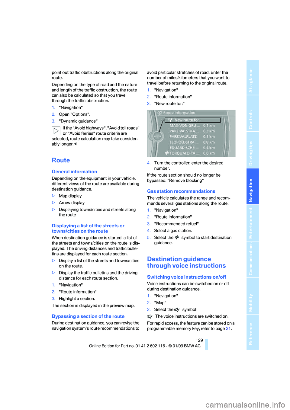
3. "New route for:"
4. Turn the controller: enter the desired
number.
If the route section sh ould no longer be
bypassed: "Remove blocking"
Gas station recommendations
The vehicle calculates the range and recom-
mends several gas stations along the route.
1. "Navigation"
2. "Route information"
3. "Recommended refuel"
4. Select a gas station.
5. Select the symbol to start destination
guidance.
Destination guidance
through voice instructions
Switching voice in structions on/off
Voice instructions can be switched on or off
during destination guidance.
1."Navigation"
2. "Map"
3. Select the symbol
The voice instructions are switched on.
For rapid access, the feat ure can be stored on a
programmable memory key, refer to page21.
Page 136 of 248
What to do if …
134
What to do if …
What to do if …
>The current position cannot be displayed?
The position is in an unrecognized region, in
a poor reception area, or the system is in the
process of determining the position.
Reception is generally available when you
are in the open.
> Destination guidance does not accept an
address without the street name?
A downtown area cannot be determined for
the town or city that has been entered. Input
any street in the selected town/city and
start destination guidance.
> The destination guidance does not accept a
destination?
The destination data is not contained in the
navigation data. Choose a destination as
close as possible to the original one.
> The letters for a destination cannot be
selected during destination entry?
The stored data do not contain the data of
the destination. Select a destination that is
as close as possible to the original.
> Voice instructions are no longer issued
before intersections during destination
guidance?
The area has not yet been fully recorded, or
you have left the recommended route and
the system requires a few seconds to calcu-
late a new route suggestion.
Page 177 of 248
175
Entertainment
Reference
At a glance
Controls
Driving tips
Communications
Navigation
Mobility
Inserting mobile phone
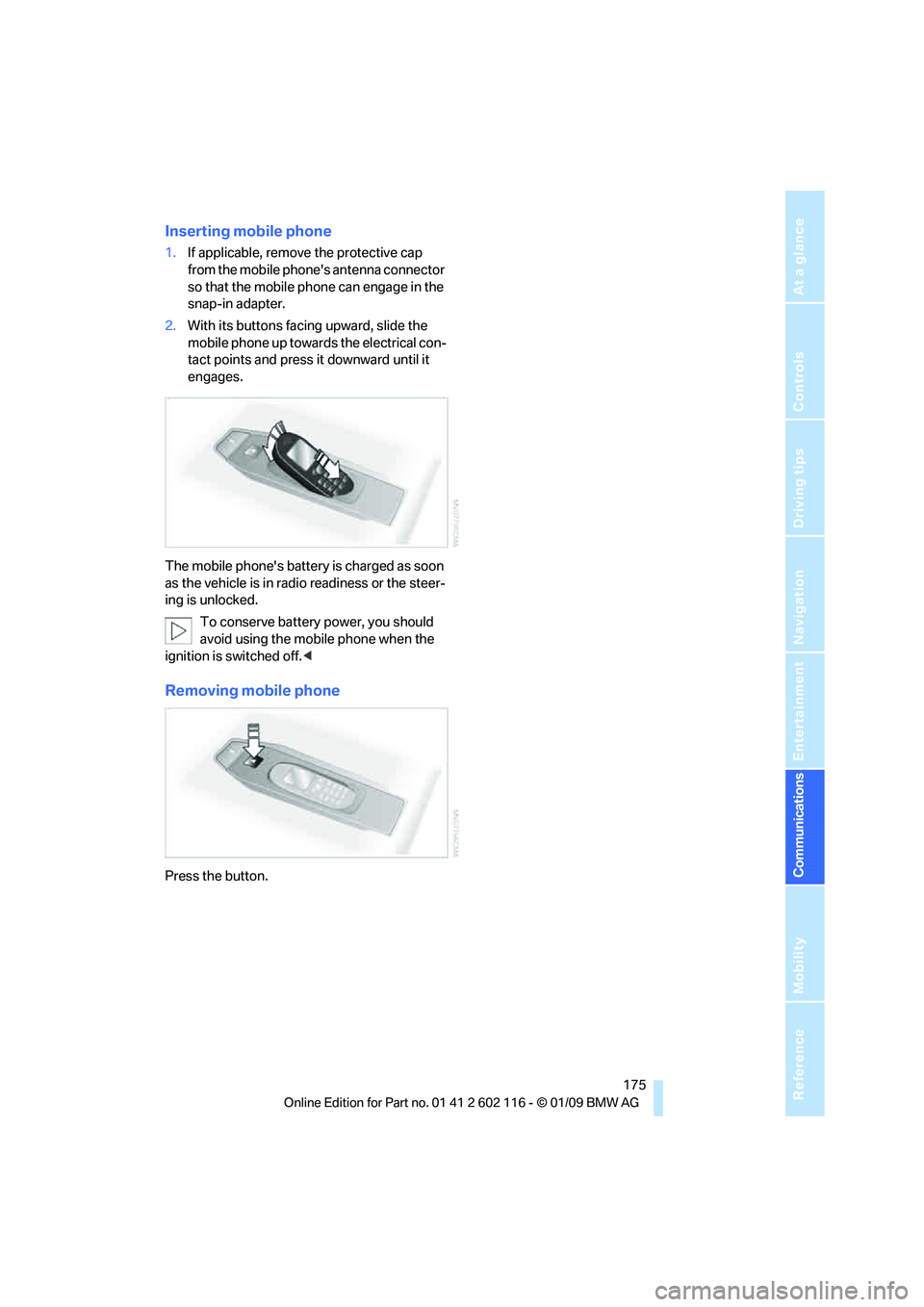
1. If applicable, remove the protective cap
from the mobile phone's antenna connector
so that the mobile phone can engage in the
snap-in adapter.
2. With its buttons facing upward, slide the
mobile phone up towards the electrical con-
tact points and press it downward until it
engages.
The mobile phone's battery is charged as soon
as the vehicle is in radi o readiness or the steer-
ing is unlocked.
To conserve battery power, you should
avoid using the mobile phone when the
ignition is switched off.<
Removing mobile phone
Press the button.
Page 196 of 248
Wheels and tires
194
Temperature
The temperature grades are A, the highest, B,
and C, representing the tire's resistance to the
generation of heat and its ability to dissipate
heat when tested under controlled conditions
on a specified indoor laboratory test wheel.
Sustained high temperature can cause the
material of the tire to degenerate and reduce
tire life, and excessive temperature can lead to
sudden tire failure. The grade C corresponds to
a level of performance which all passenger car
tires must meet under the Federal Motor Vehi-
cle Safety Standard No. 109. Grades B and A
represent higher levels of performance on the
laboratory test whee l than the minimum
required by law.
The temperature grade for this tire is
established for a tire that is properly
inflated and not overloaded. Excessive speed,
underinflation, or excessi ve loading, either sep-
arately or in combination, can cause heat
buildup and possible tire failure. <
RSC – Run-Flat Tires
You will recognize Run-Flat Tires by a circular
symbol containing the letters RSC on the side
of the tire, refer to page195.
M+S
Winter and all-season tires.
These have better winter properties than sum-
mer tires.
XL
Designation for specia lly reinforced tires.
Tire condition
Inspect your tires frequently for tread wear,
signs of damage and for foreign objects lodged
in the tread. Check the tread depth.
Minimum tread depth
The tread depth should not drop below 1/8 in/
3mm, although, for exam ple, European legisla-
tion only specifies a minimum tread depth of 1/16 in/1.6 mm. At tread depths below 1/8 in/
3 mm there is an increased risk of high-speed
hydroplaning, even when only small amounts of
water are present on the road surface.
When winter tires wear down past a tread depth
of 1/6 in/4 mm, they become perceptibly less
suitable for winter conditions. In the interest of
safety, new tires sh
ould be installed.
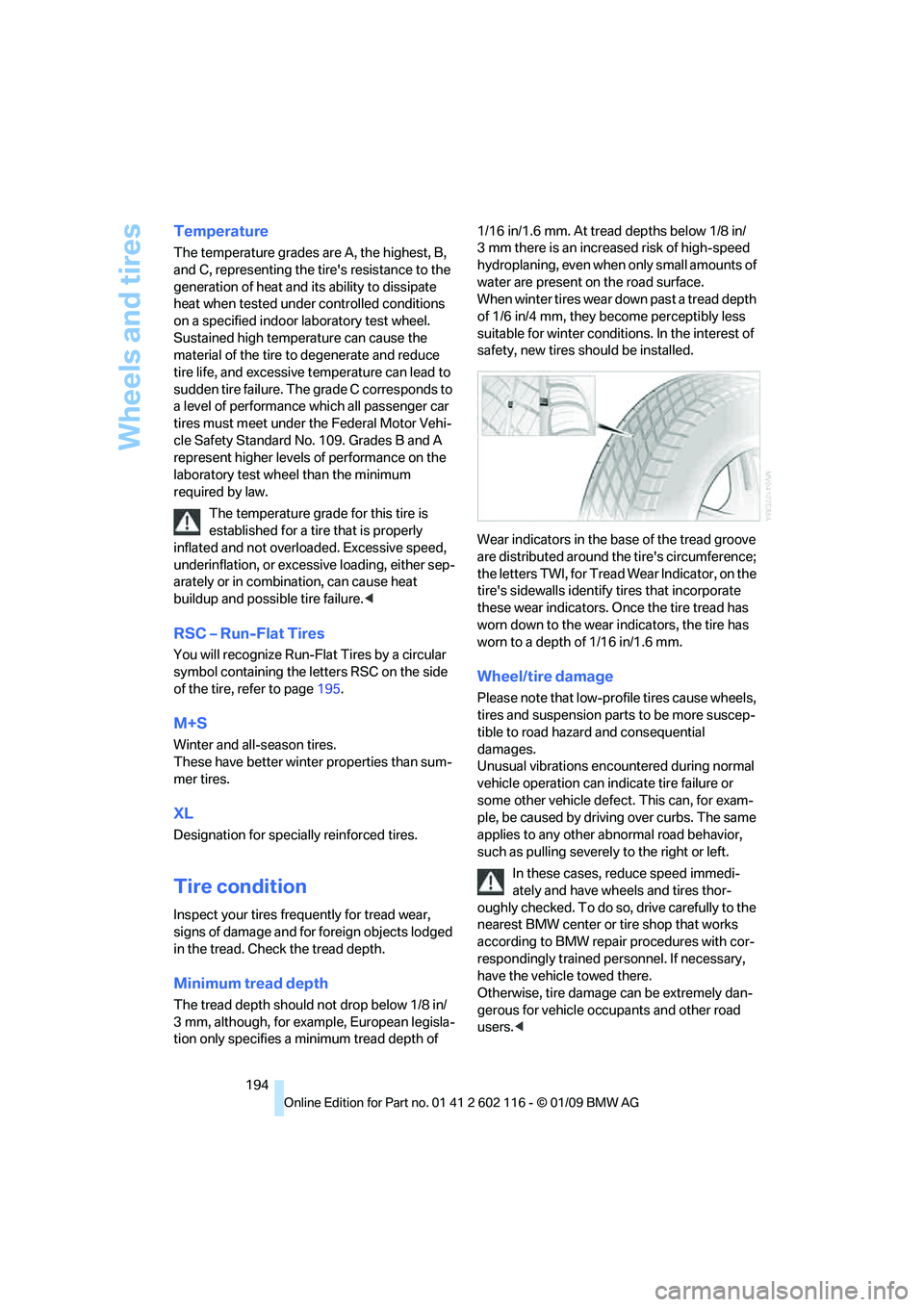
Wear indicators in the ba se of the tread groove
are distributed around th e tire's circumference;
the letters TWI, for Tread Wear Indicator, on the
tire's sidewalls identify tires that incorporate
these wear indicators. On ce the tire tread has
worn down to the wear indicators, the tire has
worn to a depth of 1/16 in/1.6 mm.
Wheel/tire damage
Please note that low-pr ofile tires cause wheels,
tires and suspension parts to be more suscep-
tible to road hazard and consequential
damages.
Unusual vibrations encountered during normal
vehicle operation can indi cate tire failure or
some other vehicle defect. This can, for exam-
ple, be caused by driving over curbs. The same
applies to any other abnormal road behavior,
such as pulling severely to the right or left.
In these cases, reduce speed immedi-
ately and have wheels and tires thor-
oughly checked. To do so, drive carefully to the
nearest BMW center or tire shop that works
according to BMW repair procedures with cor-
respondingly trained personnel. If necessary,
have the vehicle towed there.
Otherwise, tire damage can be extremely dan-
gerous for vehicle occu pants and other road
users. <
Page 211 of 248
Mobility
209Reference
At a glance
Controls
Driving tips
Communications
Navigation
Entertainment
Xenon lamps
Have any work on the xenon lamp system,
including bulb replacements, performed
only by a BMW center or a workshop that works
according to BMW repair procedures with cor-
respondingly trained pers onnel. Otherwise, if
such work is carried out improperly, the high
voltage in the system presents the danger of
fatal injuries. <
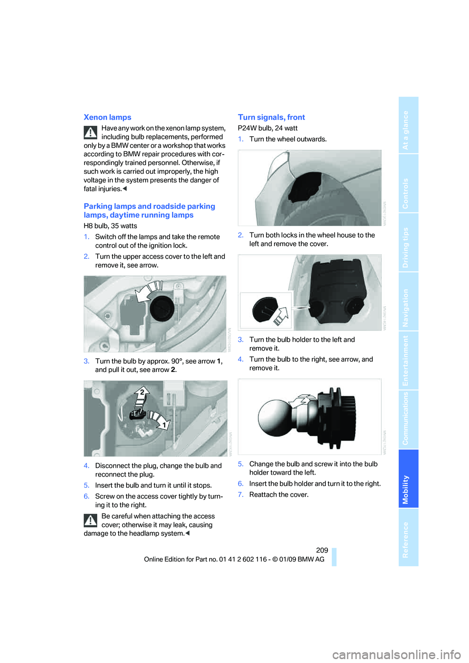
Parking lamps and roadside parking
lamps, daytime running lamps
H8 bulb, 35 watts
1.Switch off the lamps and take the remote
control out of the ignition lock.
2. Turn the upper access cover to the left and
remove it, see arrow.
3. Turn the bulb by approx. 90°, see arrow 1,
and pull it out, see arrow 2.
4. Disconnect the plug, change the bulb and
reconnect the plug.
5. Insert the bulb and turn it until it stops.
6. Screw on the access co ver tightly by turn-
ing it to the right.
Be careful when attaching the access
cover; otherwise it may leak, causing
damage to the headlamp system. <
Turn signals, front
P24W bulb, 24 watt
1.Turn the wheel outwards.
2. Turn both locks in the wheel house to the
left and remove the cover.
3. Turn the bulb holder to the left and
remove it.
4. Turn the bulb to the right, see arrow, and
remove it.
5. Change the bulb and screw it into the bulb
holder toward the left.
6. Insert the bulb holder and turn it to the right.
7. Reattach the cover.
Page 217 of 248
Mobility
215Reference
At a glance
Controls
Driving tips
Communications
Navigation
Entertainment
4.Attach one terminal clamp of the minus/–
jumper cable to the nega tive terminal of the
battery or to an engine or body ground of
the assisting vehicle.
Your BMW has a special nut as body ground
or negative pole.
5. Attach the second te rminal clamp of the
minus/– jumper cable to the negative termi-
nal of the battery or to the engine or body
ground of the vehicle to be started.
Starting the engine
1. Start the engine of the donor vehicle and
allow it to run for a few minutes at slightly
increased idle speed.
2. Start the engine on the other vehicle in the
usual way.
If the first start attempt is not successful,
wait a few minutes be fore another attempt
in order to allow the discharged battery to
recharge.
3. Let the engines run for a few minutes.
4. Disconnect the jumper cables by reversing
the above connecting sequence.
If necessary, have the battery checked and
recharged.
Never use spray fluids to start the
engine. <
Tow-starting, towing away
Observe the applicable laws and regula-
tions for tow-starting and towing
vehicles. <
Do not transport any passengers other
than the driver in a vehicle that is being
towed. <
Using a tow fitting
The screw-in tow fitting must always be carried
in the car. It can be sc rewed in at the front or
rear of the BMW.
It is stored in the onboard tool kit underneath
the floor panel in the cargo bay, refer to
page 208.
Use only the towing eyelet supplied with
the vehicle and screw it in firmly until it
stops. Use the tow fitting for towing on paved
roads only. Avoid lateral loading of the tow fit-
ting, e.g. do not lift the vehicle by the tow fitting.
Otherwise the tow fitting and the vehicle could
be damaged. <
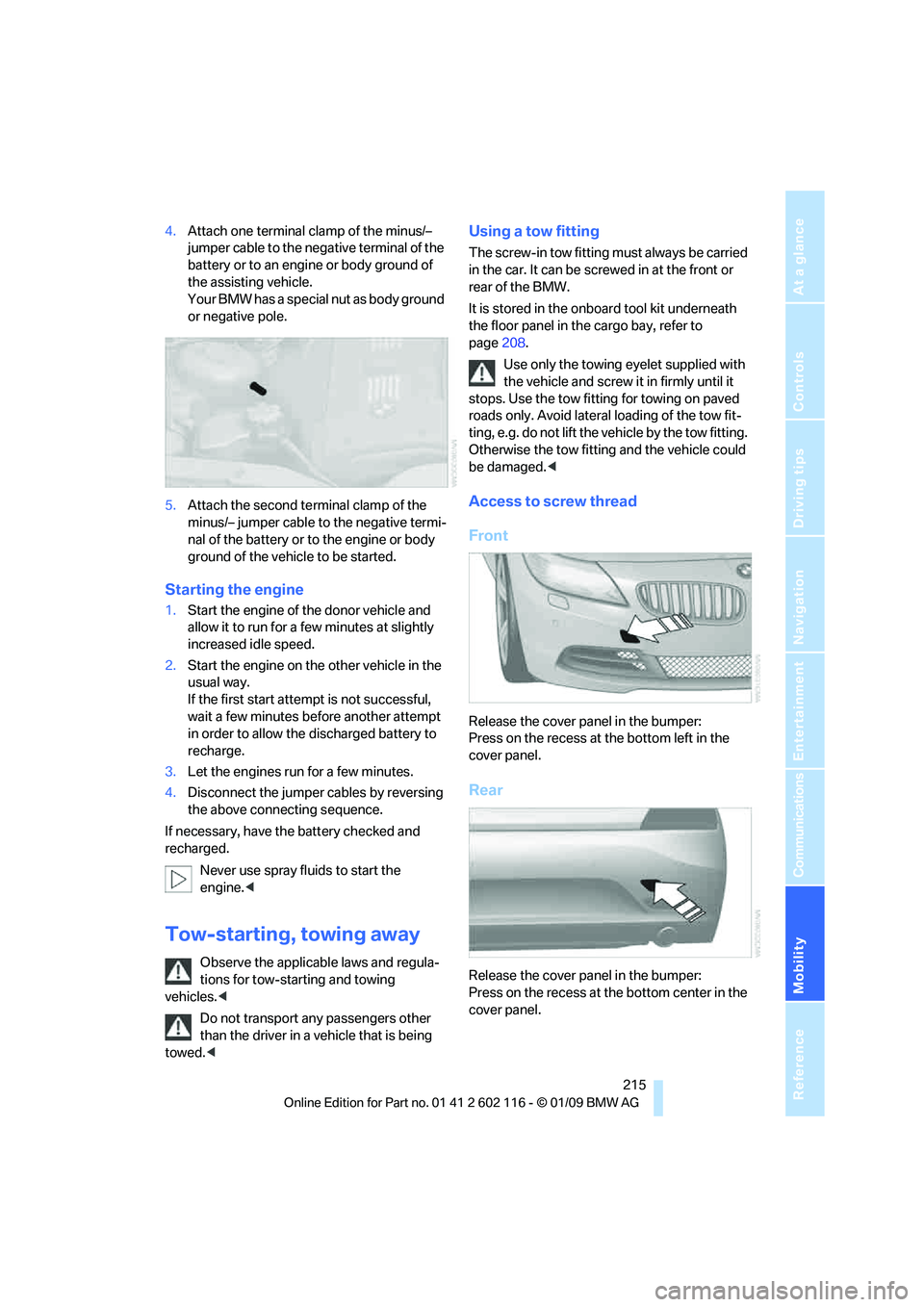
Access to screw thread
Front
Release the cover panel in the bumper:
Press on the recess at the bottom left in the
cover panel.
Rear
Release the cover panel in the bumper:
Press on the recess at the bottom center in the
cover panel.
Page 218 of 248
Giving and receiving assistance
216
Being towed
Make sure that the ignition is switched on,
refer to page50, otherwise the low-beam
headlamps, tail lamps, turn signal indicators and
windshield wipers may be unavailable.
If the electrical system fails, do not tow-start or
tow the vehicle. The electrical steering wheel
lock cannot be released and the vehicle cannot
be steered. Jump-starting, refer to page 214.
Power steering assistance is not available when
the engine is not running. Thus, braking and
steering will requir e increased effort.<
Manual transmission
Gearshift lever in neutral position.
Automatic transmission
Selector lever in position N.
Changing selector leve r positions, refer to
page 54.
Do not exceed a towing speed of 31 mph
or 50 km/h and a towing distance of
31 miles/50 km, otherwise the automatic trans-
mission may be damaged. <
7-gear sport automatic transmission
with dual clutch
Ensure that transmission lock P is not
engaged as the rear wheels will otherwise
be blocked.
When using the car wash function, refer to
page 205, note that the parking lock P is
engaged automatically after approx. 30 min-
utes, blocking the rear wheels.
If an electrical malfunction occurs or if towing
takes longer than approx. 20 minutes, manually
release the parking lock, refer to page 58.<
Do not exceed a towing speed of 31 mph
or 50 km/h and a towing distance of
31 miles/50 km, otherwise the 7-gear sport
automatic transmission may be damaged. <
Towing methods
Do not lift the vehicle by a tow fitting or
body and chassis parts, otherwise dam-
age may result. <
With a tow bar
The towing vehicle must not be lighter
than the towed vehicle, otherwise it may
be impossible to maintain control. <
The tow fittings used should be on the same
side on both vehicles. Should it prove impossi-
ble to avoid mounting the tow bar at an angle,
please observe the following:
> Clearance and maneuvering capability will
be sharply limited during cornering.
> The tow bar will generate la teral forces if it is
attached offset.
Attach the tow bar to the tow fittings only,
as attaching it to othe r parts of the vehicle
could result in damage. <
With a tow rope
When starting off in the towing vehicle, make
sure that the tow rope is taut.
To avoid jerking and the associated
stresses on vehicle components when
towing, always use nylon ropes or nylon straps.
Attach the tow rope to the tow fittings only, as
attaching it to other pa rts of the vehicle could
result in damage. <
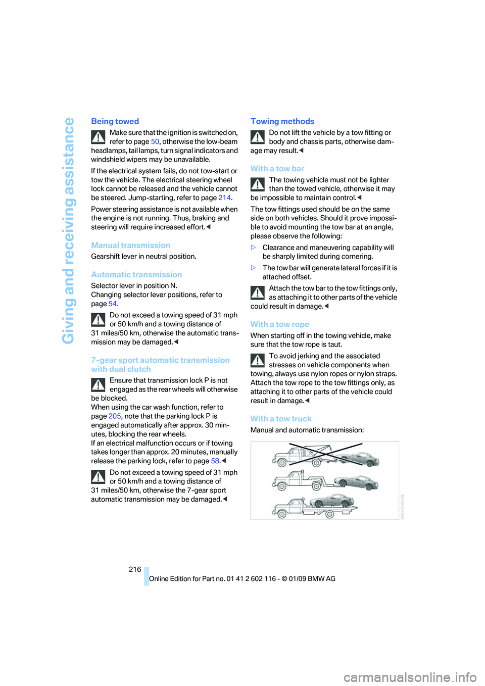
With a tow truck
Manual and automatic transmission:
Page 219 of 248
Mobility
217Reference
At a glance
Controls
Driving tips
Communications
Navigation
Entertainment
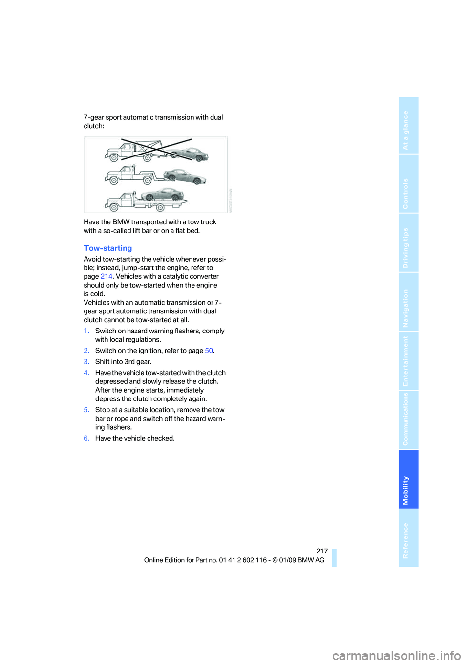
7-gear sport automatic transmission with dual
clutch:
Have the BMW transported with a tow truck
with a so-called lift bar or on a flat bed.
Tow-starting
Avoid tow-starting the vehicle whenever possi-
ble; instead, jump-start the engine, refer to
page214. Vehicles with a catalytic converter
should only be tow-st arted when the engine
is cold.
Vehicles with an automatic transmission or 7-
gear sport automatic transmission with dual
clutch cannot be tow-started at all.
1. Switch on hazard warning flashers, comply
with local regulations.
2. Switch on the ignition, refer to page 50.
3. Shift into 3rd gear.
4. Have the vehicle tow-started with the clutch
depressed and slowly release the clutch.
After the engine starts, immediately
depress the clutch completely again.
5. Stop at a suitable location, remove the tow
bar or rope and switch off the hazard warn-
ing flashers.
6. Have the vehi cle checked.