Page 281 of 324

_______________________________________________ W_ h_ a_t _ d_ o_ l _d _o_ n_ o _ w_ ? __ ffllll
•
• T he wheel bolts should be clean and easy to turn . Check for dirt
and corrosion on the mating surfaces of bo th the wheel and the
hub. Remove all dirt from these surfaces before remounting the
whee l.•
Tires with unidirectional tread design
Tires with unidirectional tread design must be mounted
with their tread pattern pointed in the right direction.
Using a spar e tir e with a tread pa ttern intended for u se
in a sp ecific direc tion
When using a spare tire with a tread pattern intended for use in a
specific direction , p lease note the following:
• T he direction of rotation is marked by an arrow on the sid e of the
tire .
• I f the spare tire has to be installed in the incorrec t direction in the
event of a flat tire , use the spare tire on ly temporarily since the tire
wi ll not be ab le to achieve its optimum performance characteristics
with regard to aquap laning, noise and wear .
• We recommend that particula r atten tion be pa id to this fact
dur ing wet weather and that you adjust your speed to match road
conditions.
• Replace the flat tire with a new one and have it installed on your
vehicle as soon as possible to restore the handling advantages of a p roper ly pointed d irection -dependent t ire. •
Notes on wheel change
Please read the information=> page 255, "New tires and replacing
tires and wheels" if you are going to use a spare tire which is
different from the tires on your veh ic le.
Aft er you change a tire :
• Che ck the ti re pre ss ure on the spare immed iately aft er
mounting .
• Have the wheel b olt t ight en ing to rque checked with a torque
wrench a s soon a s po ssible by your authorized Audi dea ler or a
q u alified service stat ion .
• On steel and a lloy wheel rims , the wheel bolt s are correctly tight
ened with a t orque of 90 ft lb (1 2 0 Nm l.
• If you noti ce w hile changing a tire that the wheel bolt s are
c o rroded and d iff ic ult to turn , then they should be repla ced befo re
you check the tightening torque.
• Repl ace the fl at t ir e w ith a new one and hav e it installed o n your
vehicle as soon as pos sib le . Remount the wheel cover .
Until then , drive wi th ext ra care and at redu ced speeds.
& WARNING
• If you are going to equip your v ehi cle wi th tire s or rim s wh ich
diffe r from tho se which were fa ctory installed , th en be sure to r ead
the infor mation
=> page 255, " New tires and repl acing tire s and
wheel s".
• Alway s ma ke sure the d amag ed w heel or e ven a flat t ire and
the jack and tool kit ar e properly secured in the lugg age comp art
ment and are not loose in the p asse nger co m partment .
• In an a ccident o r sudden maneu ver th ey could fl y fo rw ard ,
injur ing anyo ne in th e vehi cle .
• Alway s store damaged wheel , ja ck and tool s se curel y in
luggag e compartment . Oth erwi se, in an accid ent or sudd en
m aneuv er the y could fly fo rward, c au sing in jur y to pa ssenge rs in
the vehic le . •
Do-it-yourself service
Page 282 of 324

1111...__F_ u_ s_ e_s _ a_n _ d_ b_ u_lb _ s _______________________________________________ _
Fuses and bulbs
Fuses
Replacing a fuse
A problem in the electrical system may be caused by a
blown fuse.
Fig . 199 End face of
instrument panel:
removing cover plate
to access fuses
Fig .
200 Left side of
engine compartment :
fuse cover
Fuse cover on the left end face of the instrument
panel
- Switch off the ignition and the electrical component
affected. - Carefully pry the fuse cover off the instrument panel
using the ignition key or a screwdriver~ fig. 199.
- Check the fuse listing on the next pages to find out which fuse belongs to the component which has failed
~ page 281, "Fuse Locatio n, Instrument Panel left".
- Remove the blown fuse with the plastic clip provided.
The clip is located on the holder in the fuse box.
- Replace a blown fuse (recognizable by the melted metal
strip inside) w ith a fuse of the same amperage .
- Firmly snap the cover back onto the instrument panel
face.
Fuse cover in engine compartment
- Switch the ignition and the affected consumer off.
- Unlatch the fuse cover, push the two slides forward
~ fig. 200.
- Find out which fuse belongs to the equipment which
stopped working~ page 283, "Fuse location, left side of
engine compartment".
- Remove the plastic from its reta iner in the fuse box cover
(left face end of the instrument panel), place it on the
fuse in question and pull it out.
- If the fuse is burned out (recognizable by melted strips of
metal), replace it with a new fuse of the same rating.
- Replace the fuse cover.
- Push the two slides to the rear~ fig. 200. Install the fuse
cover carefully to prevent water from entering.
~
Page 283 of 324

_________________________________________________ F_ u_ s_ e_s _ a_n _d_ b_ u _ lb_ s _ __._
The various electrical circuits are protected by fuses. The fuses are
clustered in a centralized unit. The unit is located behind the face
panel at the end of the instrument panel. The crank for operating
the sunroof in case of a power failure is a lso stored behind the face
panel
~ page 49.
Two spare fuses and a sticker identifying the fuses are located on
the inside of the fuse box cover.
You are well advised to keep a supply of spare fuses in your vehicle .
Fuses with the proper ampere ratings are available at your autho
rized Audi dealer.
& WARNING
Never replace a fuse with one that has a higher amperage rating.
• A fuse with a too high amperage could damage the electrical
part and cause a fire .
0 Note
• On no accoun t should fuses be repaired (e.g . patched up with tin
foil or wire) as this may cause serious damage elsewhere in the elec
trical circuit or cause fire.
• If a fuse blows repeatedly, do not keep replacing it. Instead, have
the cause for the repeated short circuit or overload tracked and
fixed. •
Fuse Location , Instrument Panel left
Fus es which can be replaced.
Fig . 201 Fuse carrier
behind the instrument
panel end face, cover
removed
Note that the following table is accurate at the time of going to
press and is subject to change. In the event of discrepancies , the
label on the inside of the cover always takes precedence .
The power seats are protected by circuit breakers, which automati
cally reset after a few seconds after the overload has been reme -
died. .._
Vehicle care Do-it-yourself service irechnical data
Page 284 of 324

11111.___F_ u_ s _ e_s _ a_n _ d_ b_ u_lb _ s _______________________________________________ _
Equipment Amps No. Equipment Amps
Manual headlight beam adjustment, automatic 14 Electronic Stabilization Program (ESP) (control
10
1 headlight beam adjustment, AFS control mod-
10 module),
shift gate automatic transmission
ule, engine components, light switch (switch
15 Interior lights, reading lights 10
lighting/illumination), diagnosis socket
Diagnostic connector, rain sensor, a ir condit ion-
!! Automatic transmission, control module for
16 ing (control module), tire pressure monitor dis- 10
CAN data transfer (gateway), electro -mechanical
play (control module)
steering, shift gate automatic transmission, 17 Anti-theft alarm warning system 5
2 engine relay, fuel tank control unit, engine con
-10
trol unit, brakes control (ABS), Electronic Stabili- 18 Terminal 15
5
zation Program (ESP), Anti -Slip Regulation
19 All Wheel Drive
10
(ASR), brake light switch
-20 Magnetic ride 5
3 Airbag
5
-21 Not used
Air -conditioning (pressure sensor, air quality
sensor), button for Electronic Stabilization Pro- 22
Blower fan 40
gram (ESP), Anti -Slip Regulat ion (ASRl, tire pres -
23 Driver's side power window, front 30
sure mon itor display, oil level sensor, back-up
4 light switch, front seat heating, parking aid, 5 24 Power outlet front
20
seat-occupancy recognition (on USA vehicles), 25 Rear window defogger 30
navigation, garage door opener, automatic mir- 26 Power outlet in luggage compartment 20
ror dimming, heated windshield washer noz-
zles, air conditioning (control module) 27 Fuel tank control module, fuel pump 15
5 AFS headlights (left side)
5 28 Power
window, rear
30
6 AFS headlights (r ight side) 5 29 Not used
7 Not used 30 Not used
8 Not used 31 Automatic transmission (vacuum pump)
20
9 Not used 32 Headlight washer system 30
10 Not used
33 Sliding/pop-up roof
20
1 1 Not used 34 Not used
12 Central locking (front doors} 10 35 Not used
13 Central locking (rear doors) 10
36 Lumbar
support 10
Page 285 of 324

_________________________________________________ F_ u_ s_ e_s _ a_n _d_ b_ u _ lb_ s _ __.ffllll
No . Equipm ent
37 Heated seats, front
38 Passe nger s ide power window, front
39 Special function interface
Starter
41 Rear window wiper
42 Windshield wiper (washer pump)
43 Convenience electronics (control module)
44 Trailer control module
45 Trailer control module
Not used
47 Cell phone package (VOA interface)
48 Not used
49 Not used
Au tom atic cir cuit br eake rs: Amps
20
30
5
40
15
15
20
20
15
5
The electric power windows and the electric seat adjusters are protected with circuit breakers which reset automatically after the
circu it overload has been corrected.
[ i J Tip s
• Whenever replacing a fuse, always consult the sticker on the
inside of the fuse panel cover. It contains the most up-to-date infor
mation regarding the fuse arrangement. If in doubt, ask your autho
rized Audi Service advisor.
• Some of the equipment items listed are optiona l or on ly avail
able on certain model configurations. •
Fuse location , left side of engine
compartment
N M N
~ (X) 0)
Fig . 202 F use ass ign
m ent in th e e ngin e
co mpar tment in th e
e xampl e wit h
54 p lu g
in fu ses
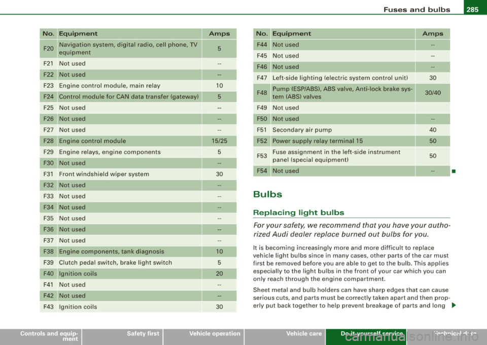
Please check your car's fuse layout, there are two different layouts.
Check the fuse layout with the fuse panel cover removed
~ page 280, "Fuse cover in engine compartment" .
Some of the equipment items listed are optional or on ly available on
certain model configurations.
Please note that the preceding table was accurate at the time of
printing and is subject to change . In the event of discrepancies, the
label on the inside of the cover a lways takes precedence.
V ariation (1 ) with 30 Plu g-in F uses
No . Equipm ent
F1 Not used
Engine components
F3 Battery voltage
F4 ESP v alves, Anti -lock brake system (ABS) valves
F5 Transmission control module
Vehicle care Do-it-yourself service
Amps
20
5
20/30
15
Technical data
Page 286 of 324

IIJII Fuses and bulbs i,.__....;,___;:,,;_,;,,.:_;__;;:_.:.:..:..=-=;____ ______________________ _
No. UEquipment Amps I No. Equipment Amps
F6 Steering wheel electronics, instrument cluster
5 F28
Not used
F7 Transmission control module 30 Fuse assignment in the left-side instrument
F29 50
F8 Navigation system, radio system 15/25 panel (special equipment)
Navigation system, digital radio, cell phone, TV F30 Power supply relay terminal
15 50
F9 equipment 5
F10 Engine control module, main relay 5/10 Variation
(2) with 54 Plug-in Fuses
F11 Not used No. Equipment
Amps
Control module for CAN data transfer (gateway) 5 F1
Vehicle
electrical system control unit (right)
30
F13 Engine control module 15/25 F2
ESP valves, Anti
-lock brake system (ABS) valves
20/30
F14 Ignition coils 20 F3 Not used
F15 Tank diagnosis, oxygen sensor 5/10 F4
Battery voltage
5
F16 Vehicle electrical system control unit (right) 30 F5 Horn
15
F17 Horn
15 F6 Engine components, fuel pump 15
F18 Audio amplifier 30 F7
Not used
F19 Front windshield wiper system 30 F8
Not used
F20 Water return
-flow pump, volume regulator valve F9 Engine components
10
F21 Oxygen sensor, vacuum pump 15 F10
Fuel tank control, mass air flow sensor
10
F22 Clutch pedal switch, brake light switch 5 F11 Oxygen sensors, in front of catalytic converter 10
F23 Engine relays, engine components
5/10/15 F12 Oxygen sensors, behind catalytic converter
10
F24 Engine components, water return-flow pump 10 F13 Automatic transmission
15
F25 Pump (ESP/ABS), ABS valve 30/40 F14 Not used
F26 Vehicle electrical system control unit (left)
30 F15 Water return-flow pump
10
F27 Secondary air pump 40 F16 Volume control valve
20
F17 Steering wheel electronics, instrument cluster
5
F18 Audio amplifier 30
F19 Navigation system, radio system 15/25
Page 287 of 324

_________________________________________________ F_ u_ s_ e_s _ a_n _ d_ b_ u_lb _ s __ ffllll
N "E .
o . qu1pm ent Amps I No. Equ ipment Amps
F20 Navigation system, digital radio, cell phone, TV
5 F44 Not used
equipm ent
F45 Not used
-
F21 Not used F46 Not used
Not used F47 Left-side lighting (electric system control unit)
30
F23 Engine control module, main re lay 10
Pump (ESP/ABS), ABS valve, Anti-lock brake sys-
F48 30/40
F24 Control module for CAN data transfer (gateway) 5 tern (ABS) valves
F25 Not used F49
Not used
Not us ed Not used
F27 Not used F51 Secondary air pump 40
Engine control module 15/25 F52 Power supply relay terminal 15 50
F29 Engine relays, eng ine components 5
F53 Fuse assign
ment in the left -side instrument
50
F30 Not used panel (special equipment)
F3 1 F
ront windshield wiper system
30
F54 Not use d •
F32 Not us ed
F33 Not used
Bulbs
F3 4 Not used
F35 Not used
Replacing light bulbs
F36 Not used F or your safety, we recommend that you have your autho -
rized Audi dealer replace burned out bulbs for you.
Not used
F37
F38 Eng ine components, ta nk diag nosis 10 It is becom ing increasingly more and more difficult to replace
vehic le light bu lbs since in many cases, other parts of the car must
F39 Clutch pedal switch, brake light switch 5 first be removed before you are able to get to the bulb . This applies
F40 Ignition coils 20 especia lly to the light bu lbs i n the front of your car which you can
only reach through the engine compartment .
F41 Not used
F42 Not used Sheet meta
l and bulb holders can have sharp edges t hat ca n cause
serious cuts, and parts must be correctly taken apart and then prop -
F43 Ignit ion coils 30 erly put back together
to he lp prevent breakage of parts and long
...
• Do-it -yourself service
Page 288 of 324

1111.___F_ u_ s _ e_s _ a_n _ d_ b_ u_lb _ s _______________________________________________ _
term damage from water that can enter housin gs that have not
b ee n prope rly resea le d.
For your safety , we r eco mmend that you have your authoriz ed Audi
dea ler rep lace any bu lbs for yo u, since you r dea le r has the p roper
to ols, t he corr ect b ulbs a nd t he e xp er tis e .
Gas discharge lamps (Xenon lights}* :
Due to th e h igh e lec trica l v o lt age, ha ve the b ulb s rep lace d by a qual
ified technician . Headlights with Xenon light can b e identified by the
hig h vo ltage stic ker .
& WARNING
Contact with high-voltage components of the electrical system
and improper replacement of gas d ischarge (Xenon } headlight
bulbs can cause serious personal injury and death.
• Xenon bulbs are pressurized and can explode when being
changed.
• Changing Xenon lamps requires the special training , instruc
tions and equipment.
• Only an authorized Audi dealer or other qualified workshop
should change the bulbs in gas discharge lamps .
& WARNING
There are parts with sharp edges on the openings and on the bulb
holders that can cause serious cuts.
• If you are uncertain about what to do , have the work performed
by an authorized Audi dealer or other qualified workshop. Serious
personal injury may result from improperly performed work.
[ i ] Tips
• If you must replace th e light bulbs yours elf, always rem ember
that the engine compartment of any vehicle is a haza rdou s area to w
or k in. A lways read and h eed al l WAR NINGS=>
pa ge 217, " E ngin e
com pa rtm ent" =>& .
• I t is best to ask your authorized A udi dealer whenever you need
t o chang e a bulb. •