2009 AUDI A4 CABRIOLET buttons
[x] Cancel search: buttonsPage 117 of 340

Warm and cold -_______________ ____,
Each of the three buttons has its own specific function (the refer
ence numbers refer to the air outlets)
~ page 115, fig . 132 .
Air di recte d t o th e w indows [-0 ]
All the air is directed to outlets 0),@ and G). Contrary to when [@I
is pressed, the amount of air remains the same.
Ai r d irecte d to th e driv er /fr ont passe nge r[~ ]
All the air is directed to outlets @,© and © in the instrument
panel. Air also is directed through the center console in the rear .
Air directed to th e fo otwell s ( ,O. I
All the air is directed to outlets © and to the outlets under the front
seats. •
Air outlets
Fig. 132 Instr ume nt pane l: w here t he ai r outlets are l ocate d
Contro ls and eq uip
ment
Air outlets => fig . 132 @ , ® and 0 can be o perated as
follows :
Outlets @
Move the slide contro l located be hind the outlet to open
or close the outlet .
Adjusting air outlets ® a nd 0
Turn the vertical thumbwheel beside the ou tlet to
increase, red uce o r shut down the a irflow from that
o utlet.
Move the small tab in t he center of the o utlet louver side
ways and up or dow n to adjust the level and direct io n of
a irfl ow.
The flow of air to the outlets is controlled either automa tically or
manually depending on the opera tion mode selected . Heated,
unheated or cooled air can flow from all out le ts.
The heater outlets for the rear footwells are located under the front seats . When you select outlets
G) , air also flows to the rear foot
we lls.
[ i ] Tips
• When defrosting/defogging the windows, air flows from outlets
0) , © and ®· To defrost or defog the windows as quickly as
possible, air outlets © and © must be opened.
• When the air conditione r is working, cooled air will flow primarily
from outlets @, G) and
@. To assure adequate cooling, outlets@,
© and © should never be completely closed .•
~ehicle care irechnical data
Page 133 of 340

Transmi ssio n -_______________ ___,
[ i J Tip s
• When you shi ft into the next lower gear, the transmission wi ll
downshi ft only when there is no poss ibi lity of over -rew ing the
engine.
• When the kick -down com es on, the transmission will shift down
to a lower gear, depending on vehicle and engine speeds .
• The tiptronic® is inoperative when the transmission is in the fail
sa fe mode .•
A pplies to vehicles : wit h 6-s pee d aut om ati c tra nsm is si on
Steering wheel with tiptronic ®
The shift buttons on the steering wheel allow the driver to
shift gears manually.
F ig . 14 4 Steer ing
w heel: Shi ft button s
-To downshif t, touch the button on the left Q .
To upshift, touch the button on the right G) .
The shift buttons are activated when the selector lever is in D, Sor
in the manual shift program (tiptronic).
Of course, you can continue to use the manual shift program with
the selector lever on the center console .•
Contro ls and eq uip
ment
A pp lies to vehicles: w ith 6-speed automat ic tra nsmission
Fail -safe mode
If tiptronic® suffers a malfunction, the fail-safe mode
maintains minimum drive ability .
In the event of particular system malfunct ions, the automatic trans
m ission switches to th e fail -saf e mode. This is signalled by all the
seg ments in the display illuminating or going out .
You can continue to move the selec tor lever to all positions . The
manual shift program (tiptronic) is switched off in the fail -safe
mode .
In selector lever posi tions D and Sand in the manual shift program,
the transmission remains in 3rd gear if 1st, 2nd or 3rd gear was engaged previous ly. The transmission remains in 5th g ear, if 4th , 5th
or 6 th gear was engaged previous ly .
The next time you drive off o r start the engine , 3rd gear is engaged .
You can continu e to use reverse gear . But the electron ic lockout for
reverse gear is turned off.
0 Note
If the transmission sw itches to fail -sa fe mo de, you should take the
vehicle to an authori zed Audi dea le rship as soon as possib le to have
the condition corrected .•
multitronic ®
Applies t o vehic les: w it h mu lt itr on ic® Co nti nuous ly V aria ble Trans mission (CVT )
General information
Your vehicle is equipped with a electron ically controlled continu
ously variable transmission (mult itronic ®l. Inside the multitronic ®
system, the gear ratios are not shifted in finite steps as in a conven
tional automatic transm ission, but rath er
contin uousl y. As a result, ...
~ehicle care Technical data
Page 139 of 340

_______________________________________________________ T_ r _a_ n_s_ m __ is_ s_ io_ n _ ___,_
Swi tching to m anual shift pro gra m
- With the selector lever in D, push lever to the right. The
display will show7
6 5 4 3 21 as soon as the selector lever
is switched over. The gear you select wi ll also be h igh
lighted in the display:::::,
page 136, fig. 149 .
To up shift
Push the selecto r lever forward to the plus position
:::::, page 136, fig. 148 G) .
To d ownshift
- Pu sh the lever to the mi nus positio n Q.
When accelerating, the transmission wi II a utomatica I ly shift into the
next higher gear before the engine reaches the maximum RPM .
When accelerating, if you apply a light throttle, the tiptronic® wil l
automatically shift into the next higher gear to save fuel. If you app ly
a heavy throttle, the transmission will stay in gear engaged until
near maximum RPM are reached, or until the driver manually shifts
into a higher gear .
If you take your foot off the accelerator peda l when driving down a
steep incline, the tiptronic ® wi ll downshift from the selected gear
into the next lower gear based on road speed and engine RPM . The
automatic downshifting is interrupted as soon as you apply throttle
again .
[ i ] Tips
• When you shift into the next lower gear, the engine will down
shift only when there is no possibility of over-revving.
• When the kick -down comes on, the transmission wi ll sh ift down
to a lower gear depending on vehicle and engine speeds.
• The tiptronic® is inoperative when the transmission is in the fai l
safe mode .•
Contro ls and eq uip
ment
Ap plies to vehicles : w it h mu ltit ron ic® Co nti nuou sly V ariable Transmi ssion ( CVT)
Steering vvheel vvith t iptronic ®
The shift buttons on the steering wheel allow the driver to
shift gears manually.
F ig. 15 0 Stee ring
w he el: S hift b utto ns
To downshift, touch the button on the left Q .
To upshift , touch the button on the r ight G) .
The shif t buttons are activated when the selector lever is in D, S or
in the manual shift program (tiptronic).
Of course, you can continue to use the manual shift program with
the selector lever on the center console. •
Applies to vehicles : wi th mu lt itro nic® Co nti nuously Var iab le Tra nsmis sion (CVT)
Fail -safe mode
If the multitronic® suffers a malfunction the fail-safe
mode maintains minimum driveability.
In the event of particular system malfunctions, the automatic trans
mission switches to the fai l-safe mode. This is signal led by all the
segments in the display illuminating or going out . _,,,
~ehicle care irechnical data
Page 142 of 340

• .___H_ o_m _ e_ L_ i_ n _k_ ®_R __________________________________________________ _
App lies to vehicles: w ith Homelin k® un ive rsal remote contro l
Programmi ng th e Hom eLink ® transmitt er
The transmitter is programmed in two phases. For rolling
code transmitters, a third phase is also necessary .
Fig. 151 Overhead
console : Homelink®
keypad
Fig.152 Frontbumper,
driver side: location of
transmitter unit
Phase 1: programming the overhead keypad
1. Make sure your vehicle is w ithin operat ing range o f the
remote controlled garage door opener .
2. Set the parking brake=>
& in "General information" on
page 139.
3. Turn the ignit ion on. Do not sta rt the engine! 4. Press and ho
ld the two outside Homelink® buttons
(D
and @for app roximately 20 seconds until indicator
light ©=:> fig.
151 beg ins to flash. Then release both
buttons . Do not hold the buttons for longer than
30
seconds.
This procedure only needs to be performed
once. It
erases the factory-set default codes and does not have to
be repeated to program additional remote controls.
5. Press and hold the Homelink ® button (D, ® or @ until
the indicator light © starts flashing
slowly. Release the
button.
- The system will remain in programming mode for 5
minutes.
Go to the front of the v ehicle and proceed w ith
phase 2.
Phase 2:
programming the bumper mounted transmitter
6. Hold the original remote control at a distance between 0-
6 in. (0-15 cm) from the b umper below the appropriate
headlight for your vehicle => fig.
152 (use the shortest
distance possible) .
7. Aim the remote control just below the
driver side head
lig ht.
8. Press and hold the act ivation button on the remote
control.
- May be different in Canada . If so, press and re-press
(cycle) the activation button on your remote control every
two seconds. -.,
Page 144 of 340

• .___H_ o_m_ e_ L_ · _,n _k_ ® __________________________________________________ _
- Press the appropriate programmed button 0,@ or@
to activate the desired remote control function~
& in
"General information" on
page 139. •
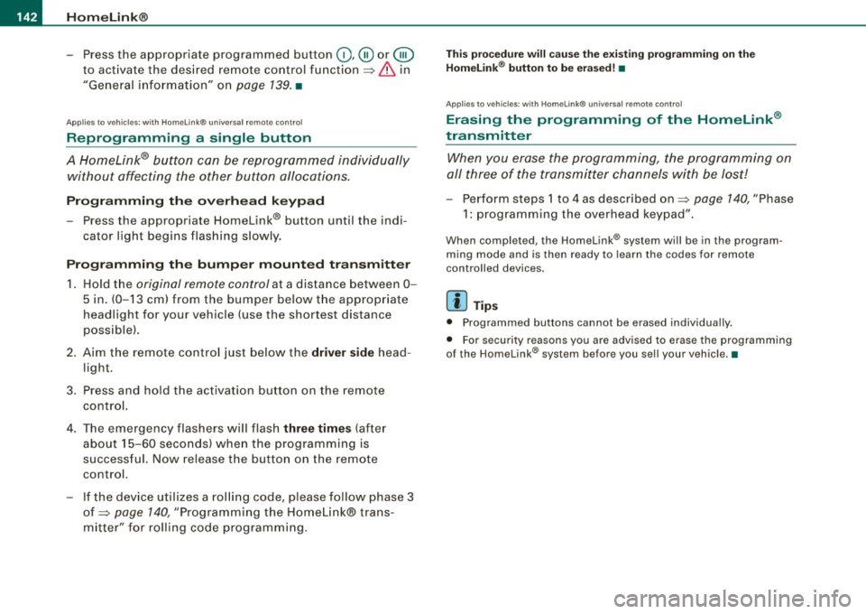
Applies to vehicles: with Homelink® universal remote contro l
Reprogramming a single button
A HomeLink® button can be reprogrammed individually without affecting the other button a/locations.
Programming the overhead keypad
- Press the appropriate Homelink® button until the indi
cator light begins flashing slowly.
Programming the bumper mounted transmitter 1. Hold t he
original remote control at a distance between 0-
5 in. (0-13 cm) from the bumper below the appropriate
headlight for your vehicle (use the shortest distance
possible).
2. Aim the remote control just below the
driver side head
light.
3. Press and hold the activation button on the remote control.
4. The emergency flashers will flash
three times (after
about
15-60 seconds) when the programming is
successful. Now release the button on the remote
control.
- If the device utilizes a rolling code, please follow phase 3
of ~
page 140, "Programming the Homelink® trans
mitter" for rolling code programming.
This procedure will cause the existing programming on the
Homelink ® button to be erased! •
App lies to vehicles: with Homelink® unive rsa l remote contro l
Erasing the programming of the Homelink ®
transmitter
When you erase the programming, the programming on
all three of the transmitter channels with be lost!
- Perform steps 1 to 4 as described on~ page 140, "Phase
1: programming the overhead keypad".
When completed , the Homelink® system will be in the prog ram
ming mode and is then ready to learn the codes for remote
controlled devices.
[I) Tips
• Programmed buttons cannot be erased individually.
• For security reasons you are advised to erase the programming
of the Homelink ® system befo re you sell your vehicle.•
Page 207 of 340

Tel.: (202) 662-0600
www.safekids.org
Safety BeltSafe U .S .A
Tel.: (800) 745-SAFE (English)
Tel.: (800) 747-SANO (Spanish)
www.carseat.org
Transport Canada
Tel.: (800) 333-0371
www.tc .gc.ca
Audi Client Relations
Tel.: (800) 822-2834 •
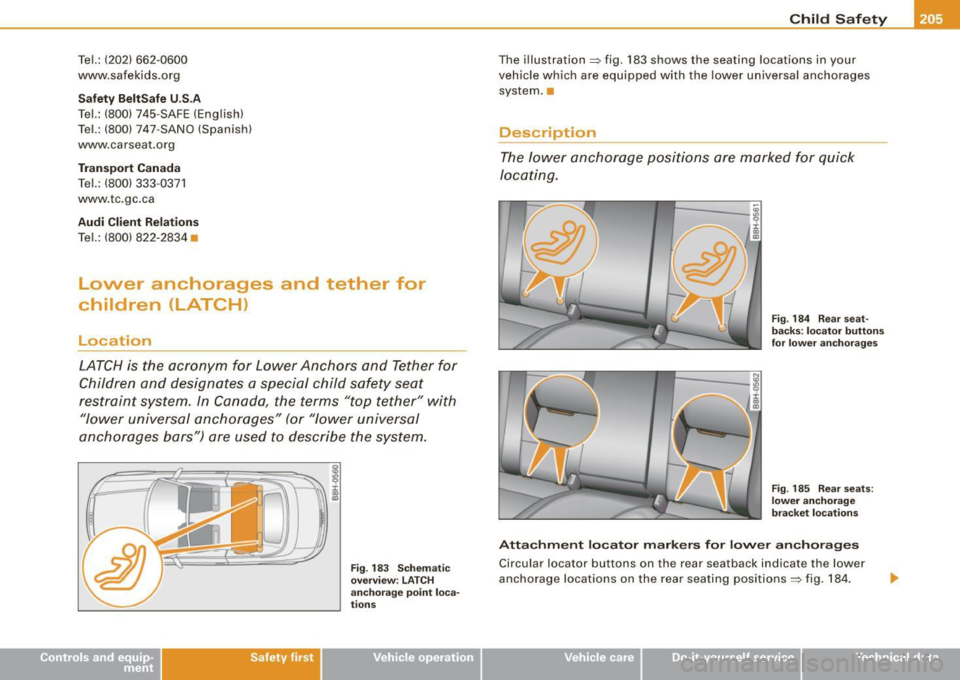
Lower anchorages and tether for
children (LATCH}
Location
LATCH is the acronym for Lower Anchors and Tether for
Children and designates a special child safety seat
restraint system . In Canada , the terms "top tether" with
"lower universal anchorages" (or "lower universal
anchorages bars") are used to describe the system.
Safety first
I :c 00
"'
Fig. 183 Schematic
overview: LATCH
anchorage point loca
tions
Child Safety
The illustration~ fig. 183 shows the seating locations in your
vehicle which are equipped with the lower universal anchorages system .•
Description
The lower anchorage positions are marked for quick
locating.
Fig. 184 Rear seat
backs : locator buttons
for lower anchorages
Fig . 185 Rear seats:
lower anchorage
bracket locations
Attachment locator markers for lower anchorages
Circular locator buttons on the rear seatback indicate the lower
anchorage locations on the rear seating positions ~ fig. 184.
~ehicle care irechnical data
Page 335 of 340

Alphabetical index -
-------------=----
Rollover bars
Lowering ... .. .... ....... ...... .. 157
See also Automatic rollover pro tection
system ... .. .... .... .... ... .... 156
Roof, e lectric ... .... .... .... ... .... .. 61
s
SAFE ...... ... .. .... .... ... .... .... . 15
Sa fe driv ing habits . ......... ....... . 146
Safety belt position .. ............. ... 164
Safety belts worn by pregnant women ..
165
Safety belt pretensioner Service and disposal . ..... .. ...... 167
Safety belt warning light .... .... .. 21,159
Sa fety be lts . . . . . . . . . . . . . . . . . . . . . . . . 163
cleaning ... .. ... ... .. ... ..... ... 242
Dange r to passengers who do not wear a
safety belt . . . . . . . . . . . . . . . . . . . . . 161
Fastening ... .... .... .... ... .... . 163
Improper ly worn . .... .... ...... .. 166
Not worn . ...... ........ ......... 161
pre tensioners ... .... .. ... .... .... 166
Safety bel t position .. .... .... .... . 164
Safety instructions ... ..... .. ... .. 162
Securing child safety seats . .... ... 200
Special considerations for pregnant
wom en . .... .... .... ... .... .... 165
Un fast ening . .... ... ..... .. .. ... . 165
Warning /indicator ligh t ..... ..... .. 159
Why YOU MUST wear them ........ 159
Worn properly .. ... ...... ... .... . 162
Safety compliance sticker .. ...... .... 312
Controls and equip
ment Safety first
Safety equipment
.... ....... .. .. .... 146 Occupants .... .... .... .... ..... .. 148
Safety features for occupant restraint and Rear passengers
... .... ...... .... . 150
pro tection . .... ...... .... ... .. . 146
Seats
Safe ty instructions Manual adjustment controls ........ 93
Eng in e compartm ent .. ... .... .... . 250 Number of seats .. .... .... .... .... 159
for booster seats . ...... .... ...... 198
Selector lever ............ .. . ..... ... 127
for using child safe ty s eats . .... .... 193
Selector lever multitronic ® ......... .. 133
for using convertible child sea ts .... 196
for using infant seats . ........... . 195
for using safety be lts . ...... .... ... 162
Monitoring the Advanced Airbag System
181 Service and
disposal
Safety belt pretensioner .. ..... .. .. 167
Service interval display .... ... .... ... .. 17
Servotron ic
Safety lock Ignition key, Automatic transmission 119
Seat adjustment Driver seat ... ...... ... .. .... ... .. 92
D river's seat memory . .......... .. 101
Front passenger seat . .... .... .... .. 93
Head restraints ................ 98, 151
Lumbar support . ...... ... .... .... . 98 Power steering
...... ............. 217
Setting Date display ............ .. ... ... .. 14
Digital clock ... .. .... .... .... .. .. . 14
Shift buttons .... .... .... ... .... 131, 137
Side airbags Description ... .... .... .. . .... .... 187
How they work .... ...... .... .... . 188
Power seats ... .. ........ .... .... . 96 Ski sack
... .............. ........... 103
Safety guidelines ... ... ....... .... . 92 Snow chains .
.... .... .... ... .... .... 285
Seat cushion extension ..... ... .... 100 Sockets
........... .... ... .. .... 105, 106
Seat belts Soft
top ... .. .... ....... .... .... ..... 61
Why YOU MUST wear them .... ... . 159 Care and cleaning
........ .... .. . . 233
Seat memory ....... ... .... .... .... . 101 Manual
operation ... ...... .... .. .. . 68
Seat position Sound system
Incorrect seat position .... .... .... 151 Replacing
.... .... .... ... .... .... 319
Seating capacity . ... .... .... .... .... 159 Sound system display
S eating position D
river information display . .... ..... 25
Driver .... .... ...... .... ... .. .... 148 Space
-saving spare wheel ... . ........ 292
Front passenger ......... ......... 149 Spare wheel ..
...... .... ... .... .... . 291
How to adjust the front sea ts .. .... . 149
Speed rat ing letter code ... ...... .... . 281
Vehicle operation Vehicle care Do-it-yourself service Technical data