Page 33 of 192

2-11
TIGHTENING TORQUES
Oil tank drain boltM8 × 1.25 1 18 1.8 13
Oil tank (upper) M6 × 1.0 1 7 0.7 5.1
Oil tank and frame M6 × 1.0 3 9 0.9 6.5
Carburetor joint clamp M4 × 0.7 2 3 0.3 2.2
Air filter joint clamp M6 × 1.0 1 3 0.3 2.2
Throttle cable adjust bolt and locknut M6 × 0.75 1 4 0.4 2.9
Throttle cable (pull) M6 × 1.0 1 4 0.4 2.9
Throttle cable (return) M12 × 1.0 1 11 1.1 8.0
Throttle cable cover M5 × 0.8 2 4 0.4 2.9
Hot starter plunger M12 × 1.0 1 2 0.2 1.4
Hot starter cable adjust bolt and locknut M6 × 0.75 1 4 0.4 2.9
△Air filter case M6 × 1.0 2 8 0.8 5.8
Air filter joint and air filter case M5 × 0.8 1 4 0.4 2.9
Air filter element M6 × 1.0 1 2 0.2 1.4
Exhaust pipe M8 × 1.25 2 20 2.0 14
△Exhaust pipe protector M6 × 1.0 3 10 1.0 7.2
△SilencerM8 × 1.25 2 30 3.0 22
Silencer clamp M8 × 1.25 1 16 1.6 11
Crankcase M6 × 1.0 11 12 1.2 8.7
Crankcase bearing stopper M6 × 1.0 11 10 1.0 7.2
Crankcase bearing stopper (crankshaft) M6 × 1.0 4 14 1.4 10
Oil level check window holder M6 × 1.0 1 10 1.0 7.2
Left crankcase cover M6 × 1.0 8 10 1.0 7.2
Right crankcase cover M6 × 1.0 8 10 1.0 7.2
Clutch cover M6 × 1.0 7 10 1.0 7.2
Crankcase oil drain bolt M10 × 1.25 1 20 2.0 14
△Crankshaft end accessing screw M32 × 1.5 1 — — —
△Timing mark accessing screwM14 × 1.5 1 — — —
Drive chain sprocket cover M6 × 1.0 2 8 0.8 5.8
Kick shaft ratchet wheel guide M6 × 1.0 2 12 1.2 8.7
Kickstarter crank M8 × 1.25 1 33 3.3 24
Primary drive gear M18 × 1.0 1 75 7.5 54
Clutch spring M6 × 1.0 5 10 1.0 7.2
Clutch boss M16 × 1.0 1 60 6.0 43
Clutch cable locknut M8 × 1.25 1 7 0.7 5.1
Clutch cable adjust bolt and locknut M6 × 0.75 1 4 0.4 2.9
Push lever shaft M6 × 1.0 1 10 1.0 7.2
Drive sprocket M18 × 1.0 1 75 7.5 54
Drive axle oil seal stopper M6 × 1.0 2 10 1.0 7.2
Segment M8 × 1.25 1 30 3.0 22
Shift guide M6 × 1.0 2 10 1.0 7.2
Stopper lever M6 × 1.0 1 10 1.0 7.2
Shift pedal M6 × 1.0 1 12 1.2 8.7
Part to be tightened
Thread size Q'tyTightening torque
Nm m•kg ft•lb
Page 34 of 192

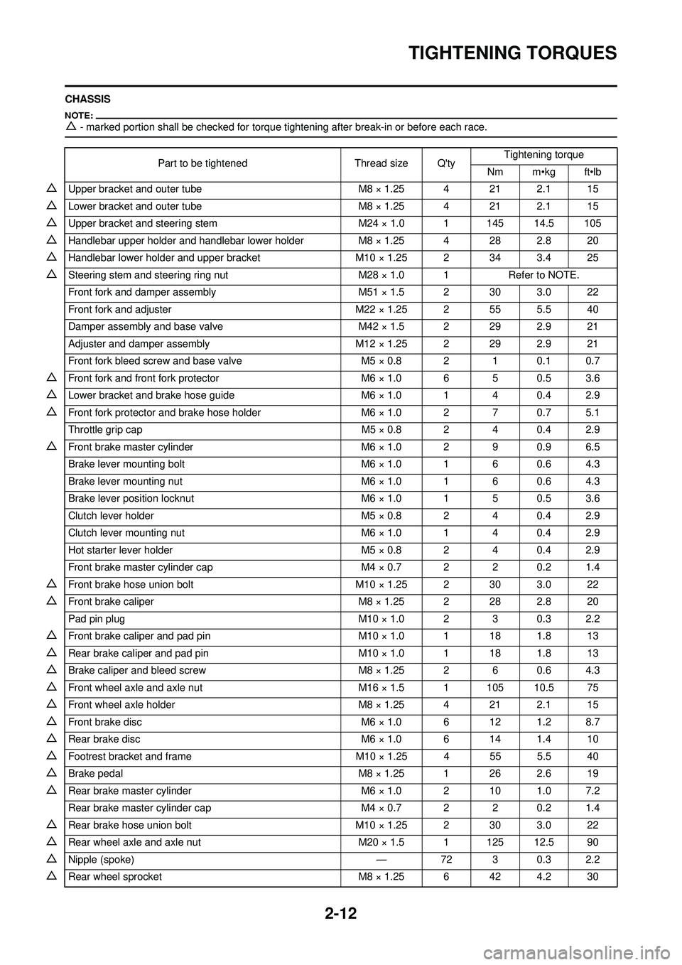
2-12
TIGHTENING TORQUES
CHASSIS
△- marked portion shall be checked for torque tightening after break-in or before each race.
Part to be tightenedThread size Q'tyTightening torque
Nm m•kg ft•lb
△Upper bracket and outer tube M8 × 1.25 4 21 2.1 15
△Lower bracket and outer tube M8 × 1.25 4 21 2.1 15
△Upper bracket and steering stem M24 × 1.0 1 145 14.5 105
△Handlebar upper holder and handlebar lower holderM8 × 1.25 4 28 2.8 20
△Handlebar lower holder and upper bracketM10 × 1.25 2 34 3.4 25
△Steering stem and steering ring nut M28 × 1.0 1Refer to NOTE.
Front fork and damper assembly M51 × 1.5 2 30 3.0 22
Front fork and adjuster M22 × 1.25 2 55 5.5 40
Damper assembly and base valve M42 × 1.5 2 29 2.9 21
Adjuster and damper assembly M12 × 1.25 2 29 2.9 21
Front fork bleed screw and base valve M5 × 0.8 2 1 0.1 0.7
△Front fork and front fork protector M6 × 1.0 6 5 0.5 3.6
△Lower bracket and brake hose guideM6 × 1.0 1 4 0.4 2.9
△Front fork protector and brake hose holderM6 × 1.0 2 7 0.7 5.1
Throttle grip cap M5 × 0.8 2 4 0.4 2.9
△Front brake master cylinderM6 × 1.0 2 9 0.9 6.5
Brake lever mounting bolt M6 × 1.0 1 6 0.6 4.3
Brake lever mounting nut M6 × 1.0 1 6 0.6 4.3
Brake lever position locknut M6 × 1.0 1 5 0.5 3.6
Clutch lever holder M5 × 0.8 2 4 0.4 2.9
Clutch lever mounting nut M6 × 1.0 1 4 0.4 2.9
Hot starter lever holder M5 × 0.8 2 4 0.4 2.9
Front brake master cylinder cap M4 × 0.7 2 2 0.2 1.4
△Front brake hose union boltM10 × 1.25 2 30 3.0 22
△Front brake caliper M8 × 1.25 2 28 2.8 20
Pad pin plug M10 × 1.0 2 3 0.3 2.2
△Front brake caliper and pad pinM10 × 1.0 1 18 1.8 13
△Rear brake caliper and pad pin M10 × 1.0 1 18 1.8 13
△Brake caliper and bleed screwM8 × 1.25 2 6 0.6 4.3
△Front wheel axle and axle nut M16 × 1.5 1 105 10.5 75
△Front wheel axle holderM8 × 1.25 4 21 2.1 15
△Front brake disc M6 × 1.0 6 12 1.2 8.7
△Rear brake disc M6 × 1.0 6 14 1.4 10
△Footrest bracket and frameM10 × 1.25 4 55 5.5 40
△Brake pedal M8 × 1.25 1 26 2.6 19
△Rear brake master cylinder M6 × 1.0 2 10 1.0 7.2
Rear brake master cylinder cap M4 × 0.7 2 2 0.2 1.4
△Rear brake hose union boltM10 × 1.25 2 30 3.0 22
△Rear wheel axle and axle nut M20 × 1.5 1 125 12.5 90
△Nipple (spoke) —72 3 0.3 2.2
△Rear wheel sprocket M8 × 1.25 6 42 4.2 30
Page 40 of 192
2-18
CABLE ROUTING DIAGRAM
CABLE ROUTING DIAGRAM
1. Fuel tank breather hose
2. Radiator hose 1
3. Connector cover
4. Cylinder head breather hose
5. Radiator hose 4
6. Clutch cable
7. Throttle position sensor lead
8. Carburetor breather hose
9. Upper engine bracket10. Hot starter cable
11. Fuel hose
12. Carburetor overflow hose
A. Insert the end of the fuel tank
breather hose into the hole in
the steering stem.
B. Install the connector cover so that it does not come in between
the radiator hose 1 and radiator. C. Aligh the paint mark on the cylin-
der head breather hose with the
front end of the hose guide.
D. Pass the cylinder head breather hose on the outside of the radia-
tor hose 1 and then between the
radiator 4 and frame.
E. Pass the clutch cable through
the cable guide.
Page 41 of 192
2-19
CABLE ROUTING DIAGRAM
F. Pass the clutch cable in front of the radiator mounting boss.
G. Pass the fuel hose between the hot starter cable and throttle po-
sition sensor lead.
H. Pass the carburetor breater hos- es so that they are not pinched
between the upper engine
bracket and carburetor.
I. Pass the carburetor breather
hoses and overflow hose so that
all there hoses do not contact
the rear shock absorber.
Page 42 of 192
2-20
CABLE ROUTING DIAGRAM
1. Hot starter cable
2. Radiator hose 2
3. Clamp
4. Ignition coil lead
5. Throttle position sensor lead
6. Hump (frame)
7. Oil hose
8. Hose guide
9. Neutral switch lead
10. CDI magneto lead
11. Clutch cable12. Radiator breather hose
13. Engine stop switch lead
14. Sub-wire harness
15. CDI unit bracket
16. CDI unit
17. Throttle cable
18. Cylinder head breather hose
A. Fasten the hot starter cable,
throttle cables, throttle position
sensor lead and ignition coil
lead. B. Fasten the throttle position sen-
sor lead behind the hump of the
frame.
C. Fasten the neutral switch lead on the oil hose.
D. Pass the neutral switch lead on the inside of the oil hose.
E. Fasten the neutral switch lead,
CDI magneto lead and radiator
breather hose.
Page 43 of 192
2-21
CABLE ROUTING DIAGRAM
F. Fasten the neutral switch lead, CDI magneto lead, radiator
breather hose and clutch cable
over the radiator mounting boss.
G. Pass the radiator breather hose in front of the radiator, on the left
of the chassis, and then be-
tween the frame and radiator
hose 4.
H. Fasten the sub-wire harness
and engine stop switch lead to
the CDI unit bracket at the white-
taped portion of the subwire har-
ness and with the clamp ends
facing downward.
I. Locate the clamp ends in the ar-
rowed range.
J. Fasten the neutral switch lead and CDI magneto lead over the
hump of the frame.
K. Fasten the hot starter cable and throttle cable onto the frame. Lo-
cate the clamp ends under the
hot starter cable.
Page 46 of 192
2-24
CABLE ROUTING DIAGRAM
1. Throttle cable
2. Clamp
3. Hot starter cable
4. Clutch cable
5. Engine stop switch lead
6. Cable guide
7. Brake hose
8. Hose guide
A. Fasten the engine stop switch lead to the handlebar. B. Pass the clutch cable and hot
starter cable through the cable
guide.
C. Pass the brake hose in front of the number plate.
D. Pass the throttle cables through the cable guide.
E. Pass the clutch cable and hot
starter cable through the cable
guide on the number plate.
Page 48 of 192

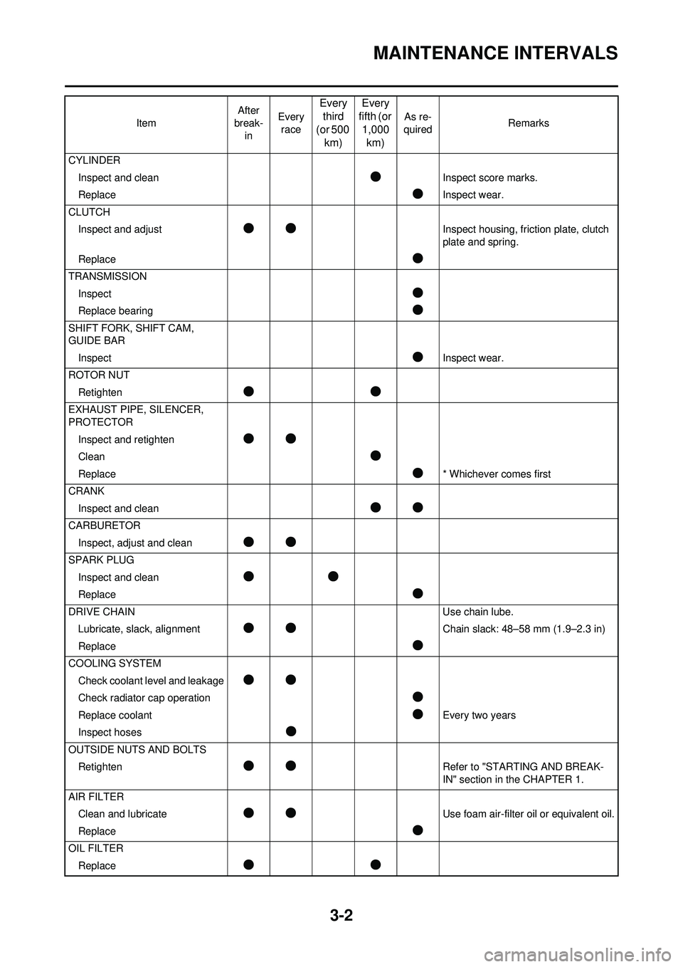
3-2
MAINTENANCE INTERVALS
CYLINDERInspect and clean
●Inspect score marks.
Replace
●Inspect wear.
CLUTCH Inspect and adjust
●●Inspect housing, friction plate, clutch
plate and spring.
Replace
●
TRANSMISSION Inspect
●
Replace bearing●
SHIFT FORK, SHIFT CAM,
GUIDE BARInspect
●Inspect wear.
ROTOR NUT Retighten
●●
EXHAUST PIPE, SILENCER,
PROTECTORInspect and retighten
●●
Clean●
Replace●* Whichever comes first
CRANK Inspect and clean
●●
CARBURETORInspect, adjust and clean
●●
SPARK PLUGInspect and clean
●●
Replace●
DRIVE CHAIN Use chain lube.
Lubricate, slack, alignment
●●Chain slack: 48–58 mm (1.9–2.3 in)
Replace
●
COOLING SYSTEM Check coolant level and leakage
●●
Check radiator cap operation●
Replace coolant●Every two years
Inspect hoses
●
OUTSIDE NUTS AND BOLTS Retighten
●●Refer to "STARTING AND BREAK-
IN" section in the CHAPTER 1.
AIR FILTER Clean and lubricate
●●Use foam air-filter oil or equivalent oil.
Replace
●
OIL FILTER Replace
●●
Item After
break-
in Every
race
Every third
(or 500 km) Every
fifth (or 1,000 km)
As re-
quired Remarks