Page 17 of 224
1-7
SPECIAL TOOLS
Dynamic spark tester
YM-34487
Ignition checker
90890-06754This instrument is necessary for
checking the ignition system compo-
nents.
Vacuum/pressure pump gauge set
YB-35956-A, 90890-06756This tool is used to check the air in-
duction system.
Digital tachometer
YU-39951-B, 90890-06760This tool is needed for observing en-
gine rpm.
YAMAHA Bond No. 1215 (ThreeB-
ond
® No. 1215)
90890-85505This sealant (Bond) is used for
crankcase mating surface, etc. Tool name/Part number How to use Illustration
Page 18 of 224

1-8
CONTROL FUNCTIONS
CONTROL FUNCTIONS
MAIN SWITCH
Functions of the respective switch po-
sitions are as follows:
ON:
The engine can be started only at this
position.
OFF:
All electrical circuits are switched off.
Main switch indicator light
The main switch "1" is equipped with
an indicator light "2" to avoid forget-
ting to turn it off. This light functions
as follows.
• It lights up with the main switch
"ON".
• It goes out when the engine in-
creases its speed after being start-
ed.
• It lights up again when the engine is
stopped.
If the indicator light will not light up
with the main switch "ON", it shows a
lack of the battery voltage. Recharge
the battery.
ENGINE STOP SWITCH
The engine stop switch "1" is located
on the left handlebar. Continue push-
ing the engine stop switch till the en-
gine comes to a stop.
START SWITCH
The start switch "1" is located on the
right handlebar. Push this switch to
crank the engine with the starter.CLUTCH LEVER
The clutch lever "1" is located on the
left handlebar; it disengages or en-
gages the clutch. Pull the clutch lever
to the handlebar to disengage the
clutch, and release the lever to en-
gage the clutch. The lever should be
pulled rapidly and released slowly for
smooth starts.
SHIFT PEDAL
The gear ratios of the constant-mesh
5 speed transmission are ideally
spaced. The gears can be shifted by
using the shift pedal "1" on the left
side of the engine.
KICKSTARTER CRANK
Rotate the kickstarter crank "1" away
from the engine. Push the starter
down lightly with your foot until the
gears engage, then kick smoothly
and forcefully to start the engine. This
model has a primary kickstarter crank
so the engine can be started in any
gear if the clutch is disengaged. In
normal practices, however, shift to
neutral before starting.
THROTTLE GRIP
The throttle grip "1" is located on the
right handlebar; it accelerates or de-
celerates the engine. For accelera-
tion, turn the grip toward you; for
deceleration, turn it away from you.FRONT BRAKE LEVER
The front brake lever "1" is located on
the right handlebar. Pull it toward the
handlebar to activate the front brake.
REAR BRAKE PEDAL
The rear brake pedal "1" is located on
the right side of the machine. Press
down on the brake pedal to activate
the rear brake.
FUEL COCK
The fuel cock supplies fuel from the
tank to carburetor and also filters the
fuel. The fuel cock has the three posi-
tions:
OFF:
With the lever in this position, fuel will
not flow. Always return the lever to
this position when the engine is not
running.
ON:
With the lever in this position, fuel
flows to the carburetor. Normal riding
is done with the lever in this position.
RES:
With the lever in this position fuel
flows to the carburetor from the re-
serve section of the fuel tank after the
main supply of the fuel has been de-
pleted. Normal riding is possible with
the lever is in this position, but it is
recommended to add fuel as soon as
possible.
Page 19 of 224

1-9
MULTI-FUNCTION DISPLAY
COLD STARTER KNOB
When cold, the engine requires a
richer air-fuel mixture for starting. A
separate starter circuit, which is con-
trolled by the cold starter knob "1",
supplies this mixture. Pull the cold
starter knob out to open the circuit for
starting. When the engine has
warmed up, push it in to close the cir-
cuit.
HOT STARTER LEVER
The hot starter lever "1" is used when
starting a warm engine. Use the hot
starter lever when starting the engine
again immediately after it was
stopped (the engine is still warm).
Pulling the hot starter lever injects
secondary air to thin the air-fuel mix-
ture temporarily, allowing the engine
to be started more easily.
SIDESTAND
This sidestand "1" is used to support
only the machine when standing or
transporting it.
• Never apply additional force to
the sidestand.
• Hold up the sidestand before
starting out.
MULTI-FUNCTION DISPLAY
Be sure to stop the machine before
making any setting changes to the
multi-function display.
The multi-function display is
equipped with the following:
BASIC MODE:
• Speedometer
•Clock
• Two tripmeters (which shows the
distance that has been traveled
since it was last set to zero)
RACE MODE:
• Timer (which shows the time that
has been accumulated since the
start of timer measurement)
• Tripmeter (which shows the accu-
mulated travel distance in timer
measurement)
• Change tripmeter digits (capable of
change to any given ones)
DESCRIPTION
Operation buttons:
1. Select button "SLCT 1"
2. Select button "SLCT 2"
3. Reset button "RST"
Screen display:
4. Tripmeter indicator
5. Tripmeter indicator
6. Timer indicator
7. Clock/Timer
8. Speedometer
9. Odometer/Tripmeter
The operation buttons can be pushed
in the following two manners:
Short push: Push the button. ( )
Long push: Push the button for 2 sec-
onds or more. ( )
BASIC MODE
Changing speedometer display
(for U.K.)
1. Push the "SLCT2" button for 2
seconds or more to change the
speedometer units. The speed-
ometer display will change in the
following order:
MPH→km/h→MPH.Setting the time
1. Push the "SLCT1" button for 2
seconds or more to enter the time
setting mode.
2. Push the "RST" button to change
the display for time indication.
The display will change in the fol-
lowing order:
Hour→Minute→Second→Hour.
The digits capable of setting go on
flashing.
3. Push the "SLCT1" button (plus) or
"SLCT2" button (minus) and
change the time. A long push on
the button will fast-forward the
time.
4. To end the setting, push the
"RST" button for 2 seconds or
more.
• In a 30-second absence of button
operation, the setting will come to
an end with the indicated time.
• To reset the seconds, push the
"SLCT1" button or "SLCT2" button.
Changing odometer and tripmeter
A/B (TRIP A/B)
1. Push the "SLCT2" button to
change the tripmeter display. The
display will change in the follow-
ing order:
Odometer →TRIP A→TRIP B→
TRIP A→Odometer.
Page 20 of 224

1-10
MULTI-FUNCTION DISPLAY
To reset the digits, select the tripme-
ter involved and push the "RST" but-
ton for 2 seconds or more.
CHANGEOVER TO BASIC MODE/
RACE MODE
• Measurement using the timer func-
tion can be made in RACE MODE.
• Indicator will light up as an
identifier that shows RACE MODE
has been selected.
• RACE MODE cannot display the
functions as in BASIC MODE.
• Changeover to RACE MODE forc-
es the digits for tripmeter A (TRIP
A) in BASIC MODE to be reset.
Changeover from BASIC MODE to
RACE MODE
1. Push the "SLCT1" button and
"SLCT2" button for 2 seconds or
more at the same time to change
over to RACE MODE.
Changeover to RACE MODE will put
manual start measurement on stand-
by causing and to flash. (For
manual start, refer to "Putting mea-
surement on standby" in "RACE
MODE".)
Returning to BASIC MODE from
RACE MODE
It is possible to return to BASIC
MODE with timer measurement at a
stop.
1. Check that the timer is not in op-
eration. If the timer is in operation,
stop the timer by pushing the
"SLCT1" button and "SLCT2" but-
ton at the same time.
2. Push the "SLCT1" button and
"SLCT2" button for 2 seconds or
more at the same time to change
over to BASIC MODE.
RACE MODE
Putting measurement on standby
Starting measurement consists of the
following two starts, either of which
can be selected.
• Manual start
Starting measurement by the rider
himself operating the button. (A long
push on the "SLCT2" button will put
measurement on standby.)
• Auto start
Starting timer measurement automat-
ically on detection of the movement of
the machine. (A long push on the
"SLCT1" button will put measurement
on standby.)
Manual start
Initial setting at changeover to RACE
MODE will remain for manual start.
1. Check that changeover to RACE
MODE has been made. (Refer to
"Changeover from BASIC MODE
to RACE MODE".)
When the machine is made ready for
a run by manual start, and will
start flashing.
2. Start timer measurement by
pushing the "RST" button.
3. When stopping timer measure-
ment, pushing the "SLCT1" but-
ton and "SLCT2" button at the
same time.
If the machine is run while timer mea-
surement is not made, no change will
occur to the digit in tripmeter A (TRIP
A).
4. To resume the measurement,
again push the "SLCT1" button
and "SLCT2" button at the same
time.
Auto start
1. Check that changeover has been
made to RACE MODE. (Refer to
"Changeover from BASIC MODE
to RACE MODE".)
2. Make the machine ready for a run
by pushing the "SLCT1" button for
2 seconds or more.
When the measurement is made
ready for a run by auto start, and
will start flashing. Timer display
will turn on scrolling from left to right.
3. Run the machine and start timer
measurement.
4. To stop timer measurement,
pushing the "SLCT1" button and
"SLCT2" button at the same time.
Page 21 of 224
.
5. To resume the measurement,
again pushing the \"")
1-11
MULTI-FUNCTION DISPLAY
If the machine is run while timer mea-
surement is not made, no change will
occur to the digit in tripmeter A (TRIP
A).
5. To resume the measurement,
again pushing the "SLCT1" button
and "SLCT2" button at the same
time.
Resetting measurement data
Resetting can be made in the follow-
ing two manners.
Resetting is possible while timer
measurement is made:
• Reset tripmeter A.
Resetting is possible while timer
measurement is not made:
• Reset tripmeter A and timer.
Resetting tripmeter A (TRIP A)
1. Check that the timer is in opera-
tion. If the timer is not in opera-
tion, start the timer by pushing the
"SLCT1" button and "SLCT2" but-
ton at the same time.
2. Reset tripmeter A (TRIP A) dis-
play by pushing the "RST" button
for 2 seconds or more.
If reset, and travel distance dis-
play will go on flashing for four sec-
onds.
Resetting tripmeter A (TRIP A) and
timer
1. Check that the timer is not in op-
eration. If the timer is in operation,
stop it by pushing the "SLCT1"
button and "SLCT2" button at the
same time.
2. Reset all measured data by push-
ing the "RST" button for 2 sec-
onds or more.
• Resetting will reset the timer display
and travel distance display and put
measurement on standby.
• Auto start attempt will put measure-
ment on standby as such. Likewise,
manual start attempt will put mea-
surement on standby as such.
Correcting tripmeter A (TRIP A)
1. Change the travel distance dis-
play by pushing the "SLCT1" but-
ton (plus) or "SLCT2" button
(minus). A long push on the but-
ton will fast-forward the change.
Change can be made any time while
timer measurement is or is not being
made.
Page 22 of 224
1-12
MULTI-FUNCTION DISPLAY
FUNCTION DIAGRAM
A short push on the button changes
the operation in the arrowed direction.
A short push on the button changes
the operation in both arrowed directions.
A long push on the button changes the
operation in the arrowed direction.
A long push on the button changes the
operation in both arrowed directions.Meter function
Function that can be performed whether
the time is or is not in operation.
Extent to which the meter can operate
Clock
BASIC MODE
Tripmeter
ODO TRIP A TRIP B ODO
Speedometer
(for U.K.)
MPH
km/h MPH
Putting measurement on
standby
Manual startAuto start
RACE MODE
Timer in operation
Reset
TRIP ACorrect
TRIP AMeasurement starts as the
machine moves
Timer not in
operation
Correct
TRIP AReset
TRIP A &
timer
Page 23 of 224
1-13
MULTI-FUNCTION DISPLAY
The following diagram illustrates the
multi-function display regarding the
direction and operation condition in-
volved in each of its functions.
A. A short push on the button
changes the operation in the ar-
rowed direction.
B. A short push on the button
changes the operation in both
arrowed directions.
C. A long push on the button
changes the operation in the ar-
rowed direction.
D. A long push on the button
changes the operation in both
arrowed directions.
E. Meter function
F. Function that can be performed
whether the time is or is not in
operation.
G. Extent to which the meter can
operate
1.BASIC MODE
2. Clock
3. Trip meter
4. Speedometer (for U.K.)
5.RACE MODE
6. Putting measurement on stand-
by
7. Manual start
8. Auto start
9. Measurement starts as the ma-
chine moves
10. Timer in operation
11. Reset TRIP A
12. Correct TRIP A
13. Timer not in operation
14. Reset TRIP A & timer
Page 24 of 224

1-14
STARTING AND BREAK-IN
STARTING AND BREAK-IN
FUEL
Always use the recommended fuel as
stated below. Also, be sure to use
new gasoline the day of a race.
Use only unleaded gasoline. The
use of leaded gasoline will cause
severe damage to the engine inter-
nal parts such as valves, piston
rings, and exhaust system, etc.
If knocking or pinging occurs, use a
different brand of gasoline or higher
octane grade.
• For refueling, be sure to stop the
engine and use enough care not
to spill any fuel. Also be sure to
avoid refueling close to a fire.
• Refuel after the engine, exhaust
pipe, etc. have cooled off.
HANDLING NOTE
Never start or run the engine in a
closed area. The exhaust fumes
are poisonous; they can cause
loss of consciousness and death
in a very short time. Always oper-
ate the machine in a well-ventilated
area.
• The carburetor on this machine
has a built-in accelerator pump.
Therefore, when starting the en-
gine, do not operate the throttle
or the spark plug will foul.
• Unlike a two-stroke engine, this
engine cannot be kick started
when the throttle is open be-
cause the kickstarter may kick
back. Also, if the throttle is open
the air/fuel mixture may be too
lean for the engine to start.
• Before starting the machine, per-
form the checks in the pre-opera-
tion check list.
AIR FILTER MAINTENANCE
According to "CLEANING THE AIR
FILTER ELEMENT" section in the
CHAPTER 3, apply the foam-air-filter
oil or its equivalent to the element.
(Excess oil in the element may ad-
versely affect engine starting.)
STARTING A COLD ENGINE
This model is equipped with an igni-
tion circuit cut-off system. The engine
can be started under the following
conditions.
• When the transmission is in neutral.
• When the clutch is disengaged with
the transmission in any position.
However, it is recommended to shift
into neutral before starting the en-
gine.
1. Inspect the coolant level.
2. Turn the fuel cock to "ON".
3. Push on the main switch to "ON".
4. Shift the transmission into neutral.
5. Fully open the cold starter knob
"1".
6. Start the engine by pushing the
start switch or by kicking the kick-
starter crank.
If the engine fails to start by pushing
the start switch, release the switch,
wait a few seconds, and then try
again. Each starting attempt should
be as short as possible to preserve
the battery. Do not crank the engine
more than 10 seconds on any one at-
tempt. If the engine does not start
with the starter motor, try using the
kickstarter crank.
• If the starter motor will not turn
when pushing the start switch,
stop pushing it immediately and
kick start the engine in order to
avoid the load on the motor.
• Do not open the throttle while
kicking the kickstarter crank.
Otherwise, the kickstarter crank
may kick back.
7. Return the cold starter knob to its
original position and run the en-
gine at 3,000–5,000 r/min for 1 or
2 minutes.
Since this model is equipped with an
accelerator pump, if the engine is
raced (the throttle opened and
closed), the air/fuel mixture will be too
rich and the engine may stall. Also
unlike a two-stroke engine, this model
can idle.
Do not warm up the engine for ex-
tended periods of time.
STARTING A WARM ENGINE
Do not operate the cold starter knob
and throttle. Pull the hot starter lever
"1" and start the engine by pushing
the start switch or by kicking the kick-
starter crank forcefully with a firm
stroke. As soon as the engine starts,
Release the hot starter lever to close
the air passage.
Restarting an engine after a fall
Pull the hot starter lever and start the
engine. As soon as the engine starts,
Release the hot starter lever to close
the air passage. Recommended fuel:
Premium unleaded
gasoline only with a re-
search octane number
of 95 or higher.
 1
1 2
2 3
3 4
4 5
5 6
6 7
7 8
8 9
9 10
10 11
11 12
12 13
13 14
14 15
15 16
16 17
17 18
18 19
19 20
20 21
21 22
22 23
23 24
24 25
25 26
26 27
27 28
28 29
29 30
30 31
31 32
32 33
33 34
34 35
35 36
36 37
37 38
38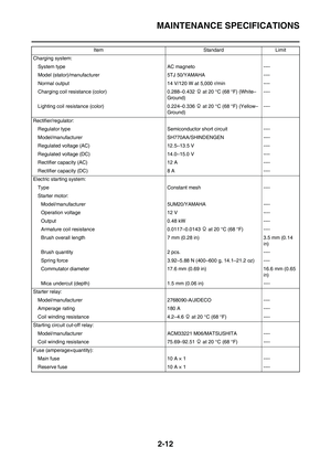 39
39 40
40 41
41 42
42 43
43 44
44 45
45 46
46 47
47 48
48 49
49 50
50 51
51 52
52 53
53 54
54 55
55 56
56 57
57 58
58 59
59 60
60 61
61 62
62 63
63 64
64 65
65 66
66 67
67 68
68 69
69 70
70 71
71 72
72 73
73 74
74 75
75 76
76 77
77 78
78 79
79 80
80 81
81 82
82 83
83 84
84 85
85 86
86 87
87 88
88 89
89 90
90 91
91 92
92 93
93 94
94 95
95 96
96 97
97 98
98 99
99 100
100 101
101 102
102 103
103 104
104 105
105 106
106 107
107 108
108 109
109 110
110 111
111 112
112 113
113 114
114 115
115 116
116 117
117 118
118 119
119 120
120 121
121 122
122 123
123 124
124 125
125 126
126 127
127 128
128 129
129 130
130 131
131 132
132 133
133 134
134 135
135 136
136 137
137 138
138 139
139 140
140 141
141 142
142 143
143 144
144 145
145 146
146 147
147 148
148 149
149 150
150 151
151 152
152 153
153 154
154 155
155 156
156 157
157 158
158 159
159 160
160 161
161 162
162 163
163 164
164 165
165 166
166 167
167 168
168 169
169 170
170 171
171 172
172 173
173 174
174 175
175 176
176 177
177 178
178 179
179 180
180 181
181 182
182 183
183 184
184 185
185 186
186 187
187 188
188 189
189 190
190 191
191 192
192 193
193 194
194 195
195 196
196 197
197 198
198 199
199 200
200 201
201 202
202 203
203 204
204 205
205 206
206 207
207 208
208 209
209 210
210 211
211 212
212 213
213 214
214 215
215 216
216 217
217 218
218 219
219 220
220 221
221 222
222 223
223

