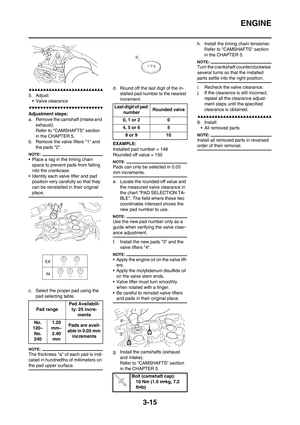
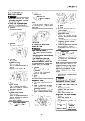
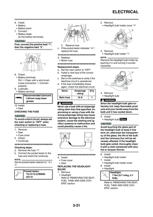
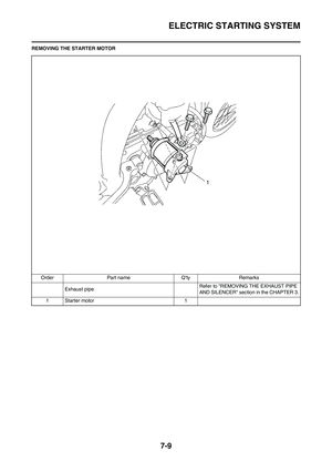
Page 169 of 224
6-8
FRONT BRAKE AND REAR BRAKE
DISASSEMBLING THE BRAKE CALIPER
Order Part name Q'ty Remarks
A. Front
B. Rear
AB
1Pad pin 11
2 Brake pad 2 2
3 Pad support 1 1
4 Brake caliper piston 2 1 Refer to removal section.
5 Brake caliper piston dust seal 2 1 Refer to removal section.
6 Brake caliper piston seal2 1 Refer to removal section.
Page 170 of 224
6-9
FRONT BRAKE AND REAR BRAKE
DISASSEMBLING THE BRAKE MASTER CYLINDER
Order Part name Q'ty Remarks
A. Front
B. Rear
1 Brake master cylinder cap 1
2 Diaphragm 1
3 Reservoir float 1
4 Brake master cylinder boot 1
5 Circlip 1 Use a long nose circlip pliers.
6 Washer 1
7 Push rod 1
8 Brake master cylinder kit 1
Page 171 of 224

6-10
FRONT BRAKE AND REAR BRAKE
HANDLING NOTE
Support the machine securely so
there is no danger of it falling over.
DRAINING THE BRAKE FLUID
1. Remove:
• Brake master cylinder cap "1"
• Protector (rear brake)
Do not remove the diaphragm.
A. Front
B. Rear
2. Connect the transparent hose "2"
to the bleed screw "1" and place a
suitable container under its end.
A. Front
B. Rear
3. Loosen the bleed screw and drain
the brake fluid while pulling the le-
ver in or pushing down on the
pedal.
• Do not reuse the drained brake
fluid.
• Brake fluid may erode painted
surfaces or plastic parts. Always
clean up spilled fluid immediate-
ly.
REMOVING THE BRAKE CALIPER
PISTON
1. Remove:
• Brake caliper piston
Use compressed air and proceed
carefully.
• Cover piston with rag and use ex-
treme caution when expelling
piston from cylinder.
• Never attempt to pry out piston.
Caliper piston removal steps:
a. Insert a piece of rag into the brake
caliper to lock one brake caliper.
b. Carefully force the piston out of
the brake caliper cylinder with
compressed air.
A. Front
B. Rear
REMOVING THE BRAKE CALIPER
PISTON SEAL KIT
1. Remove:
• Brake caliper piston dust seal "1"
• Brake caliper piston seal "2"
Remove the brake caliper piston
seals and brake caliper piston dust
seals by pushing them with a finger.
Never attempt to pry out brake cal-
iper piston seals and brake caliper
piston dust seals.
Replace the brake caliper piston
seals and brake caliper piston dust
seals whenever a caliper is disas-
sembled.
A. Front
B. Rear
CHECKING THE BRAKE MASTER
CYLINDER
1. Inspect:
• Brake master cylinder inner sur-
face "a"
Wear/scratches → Replace mas-
ter cylinder assembly.
Stains→Clean.
Use only new brake fluid.
A. Front
B. Rear
2. Inspect:
• Diaphragm "1"
Crack/damage→Replace.
A. Front
B. Rear
3. Inspect: (front brake only)
• Reservoir float "1"
Damage→Replace.
Page 172 of 224

6-11
FRONT BRAKE AND REAR BRAKE
4. Inspect:
• Brake master cylinder piston "1"
• Brake master cylinder cup "2"
Wear/damage/score marks→Re-
place brake master cylinder kit.
A. Front
B. Rear
CHECKING THE BRAKE CALIPER
1. Inspect:
• Brake caliper cylinder inner sur-
face "a"
Wear/score marks→Replace
brake caliper assembly.
A. Front
B. Rear
2. Inspect:
• Brake caliper piston "1"
Wear/score marks→Replace
brake caliper piston assembly.
Replace the brake caliper piston
seals and brake caliper piston dust
seals "2" whenever a caliper is dis-
assembled.
CHECKING THE BRAKE HOSE
1. Inspect:
• Brake hose "1"
Crack/damage→Replace.HANDLING NOTE
• All internal parts should be
cleaned in new brake fluid only.
• Internal parts should be lubricat-
ed with brake fluid when in-
stalled.
• Replace the brake caliper piston
seals and brake caliper piston
dust seals whenever a caliper is
disassembled.
INSTALLING THE BRAKE
CALIPER PISTON
1. Clean:
• Brake caliper
• Brake caliper piston seal
• Brake caliper piston dust seal
• Brake caliper piston
Clean them with brake fluid.
2. Install:
• Brake caliper piston seal "1"
• Brake caliper piston dust seal "2"
Always use new brake caliper pis-
ton seals and brake caliper piston
dust seals.
• Apply the brake fluid on the brake
caliper piston seal.
• Apply the silicone grease on the
brake caliper piston dust seal.
• Fit the brake caliper piston seals
and brake caliper piston dust seals
onto the slot on brake caliper cor-
rectly.
A. Front
B. Rear
3. Install:
• Brake caliper piston "1"
Apply the brake fluid on the piston
wall.
• Install the piston with its shallow
depressed side "a" facing the
brake caliper.
• Never force to insert.
A. Front
B. Rear
INSTALLING THE FRONT BRAKE
CALIPER
1. Install:
• Pad support "1"
• Brake pad "2"
• Pad pin "3"
• Install the brake pads with their pro-
jections "a" into the brake caliper re-
cesses "b".
• Temporarily tighten the pad pin at
this point.
2. Install:
• Brake caliper "1"
• Bolt (brake caliper) "2"
3. Tighten:
• Pad pin "3"
Bolt (brake caliper):
23 Nm (2.3 m•kg, 17
ft•lb)
Pad pin:
18 Nm (1.8 m•kg, 13
ft•lb)
Page 173 of 224

6-12
FRONT BRAKE AND REAR BRAKE
4. Install:
• Pad pin plug "4"
INSTALLING THE REAR BRAKE
CALIPER
1. Install:
• Pad support "1"
• Brake pad "2"
• Pad pin "3"
• Install the brake pads with their pro-
jections "a" into the brake caliper re-
cesses "b".
• Temporarily tighten the pad pin at
this point.
2. Install:
• Brake disc cover "1"
• Bolt (brake disc cover) "2"
3. Install:
• Brake caliper "1"
• Rear wheel "2"
Refer to "FRONT WHEEL AND
REAR WHEEL" section.
4. Tighten:
• Pad pin "3"5. Install:
• Pad pin plug "4"
INSTALLING THE BRAKE
MASTER CYLINDER KIT
1. Clean:
• Brake master cylinder
• Brake master cylinder kit
Clean them with brake fluid.
2. Install:
• Brake master cylinder cup (prima-
ry) "1"
• Brake master cylinder cup (sec-
ondary) "2"
To brake master cylinder piston
"3".
Apply the brake fluid on the brake
master cylinder cup.
After installing, cylinder cup
should be installed as shown di-
rection. Wrong installation cause
improper brake performance.
A. Front
B. Rear
3. Install:
• Spring "1"
To brake master cylinder piston
"2".
Install the spring at the smaller dia.
side.
A. Front
B. Rear
4. Install:
• Brake master cylinder kit "1"
• Washer (front brake) "2"
• Push rod (rear brake) "2"
• Circlip "3"
• Brake master cylinder boot "4"
To brake master cylinder.
• Apply the brake fluid on the brake
master cylinder kit.
• Apply the silicone grease on the tip
of the push rod.
• When installing the circlip, use a
long nose circlip pliers.
A. Front
B. Rear
INSTALLING THE FRONT BRAKE
MASTER CYLINDER
1. Install:
• Brake master cylinder "1"
• Brake master cylinder bracket "2"
• Bolt (brake master cylinder brack-
et) "3"
• Install the bracket so that the arrow
mark "a" face upward.
• First tighten the bolts on the upper
side of the brake master cylinder
bracket, and then tighten the bolts
on the lower side.
Pad pin plug:
3 Nm (0.3 m•kg, 2.2
ft•lb)
Bolt (brake disc cover):
10 Nm (1.0 m•kg, 7.2
ft•lb)
Pad pin:
18 Nm (1.8 m•kg, 13
ft•lb)Pad pin plug:
3 Nm (0.3 m•kg, 2.2
ft•lb)
Bolt (brake master cylin-
der bracket):
9 Nm (0.9 m•kg, 6.5
ft•lb)
Page 174 of 224

6-13
FRONT BRAKE AND REAR BRAKE
2. Install:
• Brake lever "1"
• Bolt (brake lever) "2"
• Nut (brake lever) "3"
Apply the silicone grease on the
brake lever sliding surface, bolt and
contacting surface of the brake mas-
ter cylinder piston.
INSTALLING THE REAR BRAKE
MASTER CYLINDER
1. Install:
• Copper washer "1"
• Brake hose "2"
• Union bolt "3"
Always use new copper washers.
Install the brake hose so that its
pipe portion "a" directs as shown
and lightly touches the projection
"b" on the brake master cylinder.
2. Install:
• Brake master cylinder "1"
• Bolt (brake master cylinder) "2"
3. Install:
• Spring "1"
• Brake pedal "2"
• O-ring "3"
• Bolt (brake pedal) "4"
• Clip "5"
Apply the lithium soap base grease
on the bolt, O-ring and brake pedal
bracket.
4. Install:
•Pin "1"
• Washer "2"
• Cotter pin "3"
After installing, check the brake pedal
height. Refer to "ADJUSTING THE
REAR BRAKE" section in the CHAP-
TER 3.
INSTALLING THE FRONT BRAKE
HOSE
1. Install:
• Copper washer "1"
• Brake hose "2"
• Union bolt "3"
Always use new copper washers.
Install the brake hose so that its
pipe portion "a" directs as shown
and lightly touches the projection
"b" on the brake caliper.
2. Install:
• Brake hose holder "1"
• Bolt (brake hose holder) "2" Bolt (brake lever):
6 Nm (0.6 m•kg, 4.3
ft•lb)
Nut (brake lever):
6 Nm (0.6 m•kg, 4.3
ft•lb)
Union bolt:
30 Nm (3.0 m•kg, 22
ft•lb)
Bolt (brake master cylin-
der):
10 Nm (1.0 m•kg, 7.2
ft•lb)
Bolt (brake pedal):
26 Nm (2.6 m•kg, 19
ft•lb)
Union bolt:
30 Nm (3.0 m•kg, 22
ft•lb)
Bolt (brake hose holder):
10 Nm (1.0 m•kg, 7.2
ft•lb)
Page 175 of 224

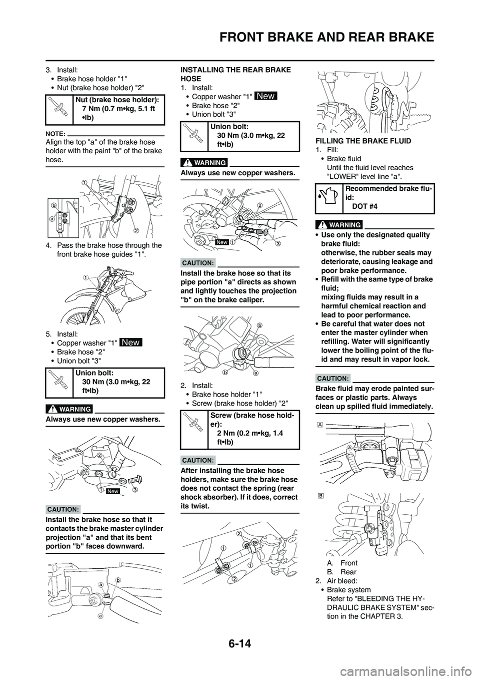
6-14
FRONT BRAKE AND REAR BRAKE
3. Install:
• Brake hose holder "1"
• Nut (brake hose holder) "2"
Align the top "a" of the brake hose
holder with the paint "b" of the brake
hose.
4. Pass the brake hose through the
front brake hose guides "1".
5. Install:
• Copper washer "1"
• Brake hose "2"
• Union bolt "3"
Always use new copper washers.
Install the brake hose so that it
contacts the brake master cylinder
projection "a" and that its bent
portion "b" faces downward.
INSTALLING THE REAR BRAKE
HOSE
1. Install:
• Copper washer "1"
• Brake hose "2"
• Union bolt "3"
Always use new copper washers.
Install the brake hose so that its
pipe portion "a" directs as shown
and lightly touches the projection
"b" on the brake caliper.
2. Install:
• Brake hose holder "1"
• Screw (brake hose holder) "2"
After installing the brake hose
holders, make sure the brake hose
does not contact the spring (rear
shock absorber). If it does, correct
its twist.
FILLING THE BRAKE FLUID
1. Fill:
• Brake fluid
Until the fluid level reaches
"LOWER" level line "a".
• Use only the designated quality
brake fluid:
otherwise, the rubber seals may
deteriorate, causing leakage and
poor brake performance.
• Refill with the same type of brake
fluid;
mixing fluids may result in a
harmful chemical reaction and
lead to poor performance.
• Be careful that water does not
enter the master cylinder when
refilling. Water will significantly
lower the boiling point of the flu-
id and may result in vapor lock.
Brake fluid may erode painted sur-
faces or plastic parts. Always
clean up spilled fluid immediately.
A. Front
B. Rear
2. Air bleed:
• Brake system
Refer to "BLEEDING THE HY-
DRAULIC BRAKE SYSTEM" sec-
tion in the CHAPTER 3. Nut (brake hose holder):
7 Nm (0.7 m•kg, 5.1 ft
•lb)
Union bolt:
30 Nm (3.0 m•kg, 22
ft•lb)
Union bolt:
30 Nm (3.0 m•kg, 22
ft•lb)
Screw (brake hose hold-
er):
2 Nm (0.2 m•kg, 1.4
ft•lb)
Recommended brake flu-
id:
DOT #4
Page 176 of 224
6-15
FRONT BRAKE AND REAR BRAKE
3. Inspect:
• Brake fluid level
Fluid at lower level→Fill up.
Refer to "CHECKING THE
BRAKE FLUID LEVEL" section in
the CHAPTER 3.
4. Install:
• Reservoir float (front brake)
• Diaphragm
• Brake master cylinder cap "1"
• Screw (bolt) {brake master cylin-
der cap} "2"
After installation, while pulling the
brake lever in or pushing down on
the brake pedal, check whether
there is any brake fluid leaking
where the union bolts are installed
respectively at the brake master
cylinder and brake caliper.
A. Front
B. Rear
5. Install: (rear brake only)
• Protector "1"
• Bolt (protector) "2"Screw (bolt) {brake mas-
ter cylinder cap}:
2 Nm (0.2 m•kg, 1.4
ft•lb)
Bolt (protector):
7 Nm (0.7 m•kg, 5.1
ft•lb)