Page 25 of 96

INSTRUMENT AND CONTROL FUNCTIONS
3-11
2
34
5
6
7
8
9
EAU44361
Fuel tank cap
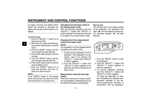
To remove the fuel tank cap
1. Insert the key into the lock and turn
it counterclockwise as shown.
2. Turn the fuel tank cap counter-
clockwise and pull it off.
To install the fuel tank cap
1. Insert the fuel tank cap into the
tank opening with the key inserted
in the lock, and then turn the cap
clockwise.2. Turn the key clockwise, and then
remove it.
NOTE:
The fuel tank cap cannot be installed
unless the key is in the lock. In addition,
the key cannot be removed if the cap is
not properly installed and locked.
WARNING
EWA10120
Make sure that the fuel tank cap is
properly closed and locked before
riding.
EAU13211
Fuel
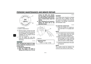
Make sure that there is sufficient fuel in
the tank. Fill the fuel tank to the bottom
of the filler tube as shown.
WARNING
EWA10880
�
Do not overfill the fuel tank, oth-
erwise it may overflow when the
fuel warms up and expands.
�
Avoid spilling fuel on the hot en-
gine.
CAUTION:
ECA10070
Immediately wipe off spilled fuel
with a clean, dry, soft cloth, since
1. Key
2. Fuel tank cap
1
2
1. Key
2. Fuel tank cap
1
2
1. Fuel level
2. Fuel tank filler tube
2
1
Page 26 of 96

INSTRUMENT AND CONTROL FUNCTIONS
3-12
1
2
3
4
5
6
7
8
9fuel may deteriorate painted surfac-
es or plastic parts.
EAU13390
CAUTION:
ECA11400
Use only unleaded gasoline. The use
of leaded gasoline will cause severe
damage to internal engine parts,
such as the valves and piston rings,
as well as to the exhaust system.
Your Yamaha engine has been de-
signed to use premium unleaded gaso-
line with a research octane number of
95 or higher. If knocking (or pinging) oc-
curs, use a gasoline of a different
brand. Use of unleaded fuel will extend
spark plug life and reduce maintenance
costs.
EAU13431
Catalytic converter
This model is equipped with a catalytic
converter in the exhaust system.
WARNING
EWA10860
The exhaust system is hot after op-
eration. Make sure that the exhaust
system has cooled down before do-
ing any maintenance work.
CAUTION:
ECA10700
The following precautions must be
observed to prevent a fire hazard or
other damages.
�
Use only unleaded gasoline.
The use of leaded gasoline will
cause unrepairable damage to
the catalytic converter.
�
Never park the vehicle near pos-
sible fire hazards such as grass
or other materials that easily
burn.
�
Do not allow the engine to idle
too long.
EAU13970
Seat
To remove the seat
Remove the bolts, and then pull the
seat off.
To install the seat
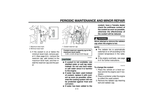
1. Insert the projection on the front of
the seat into the seat holder as
shown.
Recommended fuel:
PREMIUM UNLEADED GASOLINE
ONLY
Fuel tank capacity:
7.6 L (2.01 US gal) (1.67 Imp.gal)
Fuel reserve amount (when the fuel
level warning light comes on):
2.1 L (0.55 US gal) (0.46 Imp.gal)
1. Bolt
1
Page 27 of 96

INSTRUMENT AND CONTROL FUNCTIONS
3-13
2
34
5
6
7
8
9
2. Place the seat in the original posi-
tion, and then tighten the bolts.
NOTE:
Make sure that the seat is properly se-
cured before riding.
EAU14281
Helmet holder
To open the helmet holder, insert the
key into the lock, and then turn the key
as shown.
To lock the helmet holder, place it in the
original position, and then remove the
key.
WARNING
EWA10160
Never ride with a helmet attached to
the helmet holder, since the helmet
may hit objects, causing loss of con-
trol and possibly an accident.
EAU45200
Adjusting the front fork
This front fork is equipped with rebound
damping force adjusting screws and
compression damping force adjusting
screws.
WARNING
EWA10180
Always adjust both fork legs equal-
ly, otherwise poor handling and loss
of stability may result.
Rebound damping force
To increase the rebound damping force
and thereby harden the rebound damp-
ing, turn the adjusting screw on each
fork leg in direction (a). To decrease the
1. Projection
2. Seat holder
1
2
1. Helmet holder
2. Open.
1
2
1. Rebound damping force adjusting screw
1
(b)
(a)
Page 28 of 96
.
Compression da")
INSTRUMENT AND CONTROL FUNCTIONS
3-14
1
2
3
4
5
6
7
8
9
rebound damping force and thereby
soften the rebound damping, turn the
adjusting screw on each fork leg in di-
rection (b).
Compression damping force
1. Remove the rubber cap by pulling
it out of the front fork leg.2. To increase the compression
damping force and thereby harden
the compression damping, turn the
adjusting screw on each fork leg in
direction (a). To decrease the
compression damping force and
thereby soften the compression
damping, turn the adjusting screw
on each fork leg in direction (b).
3. Install the rubber cap.
CAUTION:
ECA10100
Never attempt to turn an adjusting
mechanism beyond the maximum or
minimum settings.
NOTE:
Although the total number of clicks of a
damping force adjusting mechanism
may not exactly match the above spec-
ifications due to small differences in
production, the actual number of clicks
always represents the entire adjusting
range. To obtain a precise adjustment,
it would be advisable to check the num-
ber of clicks of each damping force ad-
justing mechanism and to modify the
specifications as necessary.
Rebound damping setting:
Minimum (soft):
24 click(s) in direction (b)*
Standard:
10 click(s) in direction (b)*
Maximum (hard):
1 click(s) in direction (b)*
* With the adjusting screw fully turned
in direction (a)
1. Rubber cap
1
1. Compression damping force adjusting
screw
1(a) (b)
Compression damping setting:
Minimum (soft):
20 click(s) in direction (b)*
Standard:
10 click(s) in direction (b)*
Maximum (hard):
1 click(s) in direction (b)*
* With the adjusting screw fully turned
in direction (a)
Page 29 of 96

INSTRUMENT AND CONTROL FUNCTIONS
3-15
2
34
5
6
7
8
9
EAU14790
Front fork bleeding
When riding in extremely rough condi-
tions, the air temperature and pressure
in the front fork will rise. This will in-
crease the spring preload and harden
the front suspension. If this occurs,
bleed the front fork as follows.
1. Elevate the front wheel by placing
a suitable stand under the engine.
NOTE:
When bleeding the front fork, there
should be no weight on the front end of
the vehicle.
2. Remove the bleed screws and al-
low all of the air to escape fromeach fork leg.
WARNING
EWA10200
Always bleed both fork legs, other-
wise poor handling and loss of sta-
bility may result.
3. Install the bleed screws.
EAU45260
Adjusting the shock absorber
assembly
This shock absorber assembly is
equipped with a spring preload adjust-
ing ring, a rebound damping force ad-
justing dial and a compression
damping force adjusting screw.
CAUTION:
ECA10100
Never attempt to turn an adjusting
mechanism beyond the maximum or
minimum settings.
Spring preload
Spring preload adjustment should be
made by a Yamaha dealer, since this
service requires special tools and tech-
nical skills. The specified settings are
listed below.
NOTE:
The spring preload setting is deter-
mined by measuring distance A, shown
in the illustration. The shorter the dis-
tance A is, the higher the spring pre-
load; the longer distance A is, the lower
the spring preload.
1. Bleed screw
1
Page 30 of 96

INSTRUMENT AND CONTROL FUNCTIONS
3-16
1
2
3
4
5
6
7
8
9Rebound damping force
To increase the rebound damping force
and thereby harden the rebound damp-
ing, turn the adjusting dial in direction
(a). To decrease the rebound damping
force and thereby soften the rebound
damping, turn the adjusting dial in di-
rection (b).
Compression damping force
To increase the compression damping
force and thereby harden the compres-
sion damping, turn the adjusting screw
in direction (a). To decrease the com-
pression damping force and thereby
soften the compression damping, turnthe adjusting screw in direction (b).
NOTE:
Although the total number of clicks of a
damping force adjusting mechanism
may not exactly match the above spec-
ifications due to small differences in
production, the actual number of clicks
1. Distance A
Spring preload:
Minimum (soft):
Distance A = 216 mm (8.50 in)
Standard:
Distance A = 211.5 mm (8.33 in)
Maximum (hard):
Distance A = 206 mm (8.11 in)
1
1. Rebound damping force adjusting dial
Rebound damping setting:
Minimum (soft):
25 click(s) in direction (b)*
Standard:
12 click(s) in direction (b)*
Maximum (hard):
3 click(s) in direction (b)*
* With the adjusting dial fully turned in
direction (a)(a) (b) 1
1. Compression damping force adjusting
screw
Compression damping setting:
Minimum (soft):
12 click(s) in direction (b)*
Standard:
10 click(s) in direction (b)*
Maximum (hard):
1 click(s) in direction (b)*
* With the adjusting screw fully turned
in direction (a)
1 (a)
(b)
Page 31 of 96

INSTRUMENT AND CONTROL FUNCTIONS
3-17
2
34
5
6
7
8
9
always represents the entire adjusting
range. To obtain a precise adjustment,
it would be advisable to check the num-
ber of clicks of each damping force ad-
justing mechanism and to modify the
specifications as necessary.
WARNING
EWA10220
This shock absorber contains highly
pressurized nitrogen gas. For prop-
er handling, read and understand
the following information before
handling the shock absorber. The
manufacturer cannot be held re-
sponsible for property damage or
personal injury that may result from
improper handling.
�
Do not tamper with or attempt to
open the gas cylinder.
�
Do not subject the shock ab-
sorber to an open flame or other
high heat sources, otherwise it
may explode due to excessive
gas pressure.
�
Do not deform or damage the
gas cylinder in any way, as this
will result in poor damping per-formance.
�
Always have a Yamaha dealer
service the shock absorber.
EAU41940
EXUP system
This model is equipped with Yamaha’s
EXUP (EXhaust Ultimate Power valve)
system. This system boosts engine
power by means of a valve that regu-
lates the diameter of the exhaust pipe.
The EXUP system valve is constantly
adjusted in accordance with the engine
speed by a computer-controlled servo-
motor.
CAUTION:
ECA15610
The EXUP system has been set and
extensively tested at the Yamaha
factory. Changing these settings
without sufficient technical knowl-
edge may result in poor perfor-
mance of or damage to the engine.
Page 32 of 96

INSTRUMENT AND CONTROL FUNCTIONS
3-18
1
2
3
4
5
6
7
8
9
EAU15301
Sidestand
The sidestand is located on the left side
of the frame. Raise the sidestand or
lower it with your foot while holding the
vehicle upright.
NOTE:
The built-in sidestand switch is part of
the ignition circuit cut-off system, which
cuts the ignition in certain situations.
(See further down for an explanation of
the ignition circuit cut-off system.)
WARNING
EWA10240
The vehicle must not be ridden with
the sidestand down, or if the side-
stand cannot be properly moved up
(or does not stay up), otherwise the
sidestand could contact the ground
and distract the operator, resulting
in a possible loss of control.
Yamaha’s ignition circuit cut-off
system has been designed to assist
the operator in fulfilling the respon-
sibility of raising the sidestand be-
fore starting off. Therefore, check
this system regularly as described
below and have a Yamaha dealer re-pair it if it does not function proper-
ly.
EAU44890
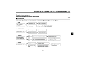
Ignition circuit cut-off system
The ignition circuit cut-off system (com-
prising the sidestand switch, clutch
switch and neutral switch) has the fol-
lowing functions.
�
It prevents starting when the trans-
mission is in gear and the side-
stand is up, but the clutch lever is
not pulled.
�
It prevents starting when the trans-
mission is in gear and the clutch le-
ver is pulled, but the sidestand is
still down.
�
It cuts the running engine when the
transmission is in gear and the sid-
estand is moved down.
Periodically check the operation of the
ignition circuit cut-off system according
to the following procedure.
WARNING
EWA10250
If a malfunction is noted, have a
Yamaha dealer check the system be-
fore riding.