Page 73 of 96

PERIODIC MAINTENANCE AND MINOR REPAIR
6-33
2
3
4
5
67
8
9
If a fuse is blown, replace it as follows.
1. Turn the key to “OFF” and turn off
the electrical circuit in question.
2. Remove the blown fuse, and then
install a new fuse of the specified
amperage.
CAUTION:
ECA10640
Do not use a fuse of a higher amper-
age rating than recommended to
avoid causing extensive damage to
the electrical system and possibly a
fire.
3. Turn the key to “ON” and turn on
the electrical circuit in question to
check if the device operates.
4. If a fuse immediately blows again,
have a Yamaha dealer check the
electrical system.
EAU45210
Replacing the headlight bulb
This model is equipped with a quartz
bulb headlight. If the headlight bulb
burns out, replace it as follows.
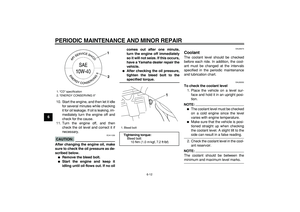
1. Remove the headlight cowling to-
gether with the headlight unit by
removing the bolts and pulling up-
ward as shown.
2. Disconnect the headlight coupler,
and then remove the bulb cover.
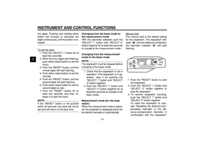
1. Fuel injection system fuse
2. Radiator fan fuse
3. Backup fuse
4. Ignition fuse
5. Signaling system fuse
6. Headlight fuse
7. Spare fuse
7
123456
Specified fuses:
Main fuse:
30.0 A
Ignition fuse:
7.5 A
Signaling system fuse:
10.0 A
Headlight fuse:
15.0 A
Radiator fan fuse:
7.5 A
Backup fuse:
7.5 A
Fuel injection system fuse:
7.5 A
1. Bolt
1
1
Page 74 of 96

PERIODIC MAINTENANCE AND MINOR REPAIR
6-34
1
2
3
4
5
6
7
8
9
3. Unhook the headlight bulb holder,
and then remove the defective
bulb.
WARNING
EWA10790
Headlight bulbs get very hot. There-
fore, keep flammable products away
from a lit headlight bulb, and do not
touch the bulb until it has cooled
down.
4. Place a new headlight bulb into po-
sition, and then secure it with the
bulb holder.
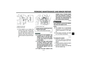
CAUTION:
ECA10660
Do not touch the glass part of the
headlight bulb to keep it free from
oil, otherwise the transparency of
the glass, the luminosity of the bulb,
and the bulb life will be adversely af-fected. Thoroughly clean off any dirt
and fingerprints on the headlight
bulb using a cloth moistened with al-
cohol or thinner.
5. Install the headlight bulb cover,
and then connect the coupler.
6. Install the headlight cowling (to-
gether with the headlight unit) by
placing it in the original position,
and then installing the bolts.
7. Have a Yamaha dealer adjust the
headlight beam if necessary.
1. Headlight coupler
2. Bulb cover
1
2
1. Headlight bulb holder
1
1. Do not touch the glass part of the bulb.
Page 75 of 96
PERIODIC MAINTENANCE AND MINOR REPAIR
6-35
2
3
4
5
67
8
9
EAU24181
Tail/brake light
This model is equipped with an
LED-type tail/brake light.
If the tail/brake light does not come on,
have a Yamaha dealer check it.
EAU24202
Replacing a turn signal light
bulb
1. Remove the turn signal light lens
by removing the screw.
2. Remove the defective bulb by
pushing it in and turning it counter-
clockwise.3. Insert a new bulb into the socket,
push it in, and then turn it clock-
wise until it stops.
4. Install the lens by installing the
screw.
CAUTION:
ECA11190
Do not overtighten the screw, other-
wise the lens may break.
1. Screw
2. Turn signal light lens
1
2
1. Turn signal light bulb
1
Page 76 of 96

PERIODIC MAINTENANCE AND MINOR REPAIR
6-36
1
2
3
4
5
6
7
8
9
EAU24310
Replacing the license plate
light bulb
1. Remove the license plate light unit
by removing the screws.
2. Remove the socket (together with
the bulb) by pulling it out.3. Remove the defective bulb by pull-
ing it out.
4. Insert a new bulb into the socket.
5. Install the socket (together with the
bulb) by pushing it in.
6. Install the license plate light unit by
installing the screws.
EAU45220
Replacing an auxiliary light
bulb
If the auxiliary light bulb burns out, re-
place it as follows.
1. Remove the headlight unit. (See
page 6-33.)
2. Remove the auxiliary light socket
(together with the bulb) by pulling it
out.
3. Remove the defective bulb by pull-
ing it out.
4. Insert a new bulb into the socket.
5. Install the auxiliary light socket (to-
gether with the bulb) by pushing it
in.
6. Install the headlight unit.
1. Screw
1
1. License plate light unit
2. License plate light bulb socket
12
1. Auxiliary light bulb socket
1
Page 77 of 96

PERIODIC MAINTENANCE AND MINOR REPAIR
6-37
2
3
4
5
67
8
9
EAU24350
Supporting the motorcycle
Since this model is not equipped with a
centerstand, follow these precautions
when removing the front and rear
wheel or performing other maintenance
requiring the motorcycle to stand up-
right. Check that the motorcycle is in a
stable and level position before starting
any maintenance. A strong wooden
box can be placed under the engine for
added stability.
To service the front wheel
1. Stabilize the rear of the motorcycle
by using a motorcycle stand or, if
an additional motorcycle stand is
not available, by placing a jack un-
der the frame in front of the rear
wheel.
2. Raise the front wheel off the
ground by using a motorcycle
stand.
To service the rear wheel
Raise the rear wheel off the ground by
using a motorcycle stand or, if a motor-
cycle stand is not available, by placing
a jack either under each side of theframe in front of the rear wheel or under
each side of the swingarm.
EAU24360
Front wheel
EAU45160
To remove the front wheel
WARNING
EWA10820
�
It is advisable to have a Yamaha
dealer service the wheel.
�
Securely support the motorcy-
cle so that there is no danger of
it falling over.
1. Loosen the front wheel axle pinch
bolts and axle nut.
1. Front wheel axle pinch bolt
2. Axle nut
2
1
Page 78 of 96

PERIODIC MAINTENANCE AND MINOR REPAIR
6-38
1
2
3
4
5
6
7
8
9
2. Lift the front wheel off the ground
according to the procedure on
page 6-37.
3. Remove the axle nut.
4. Pull the wheel axle out, and then
remove the wheel.
CAUTION:
ECA11070
Do not apply the brake after the
wheel has been removed together
with the brake disc, otherwise the
brake pads will be forced shut.
EAU45170
To install the front wheel
1. Lift the wheel up between the forklegs.
NOTE:
Make sure that there is enough space
between the brake pads before install-
ing the brake caliper onto the brake
disc.
2. Insert the wheel axle.
3. Install the wheel axle pinch bolts
and axle nut.
4. Lower the front wheel so that it is
on the ground.
5. Tighten the axle nut and the wheel
axle pinch bolts to their specified
torques.
6. Push down hard on the handlebar
several times to check for proper
fork operation.
EAU25080
Rear wheel
EAU45180
To remove the rear wheel
WARNING
EWA10820
�
It is advisable to have a Yamaha
dealer service the wheel.
�
Securely support the motorcy-
cle so that there is no danger of
it falling over.
1. Loosen the axle nut.
2. Lift the rear wheel off the ground
according to the procedure on
page 6-37.
3. Remove the axle nut and washer.
4. Loosen the locknut and drive chain
adjusting bolt on each side of the
swingarm.
1. Front wheel axle pinch bolt
2. Wheel axle
1
2
Tightening torques:
Axle nut:
63 Nm (6.3 m·kgf, 45.6 ft·lbf)
Wheel axle pinch bolt:
23 Nm (2.3 m·kgf, 16.6 ft·lbf)
Page 79 of 96

PERIODIC MAINTENANCE AND MINOR REPAIR
6-39
2
3
4
5
67
8
9
5. While supporting the brake caliper,
pull the wheel axle out.6. Push the wheel forward, and then
remove the drive chain from the
rear sprocket.
NOTE:
The drive chain does not need to be
disassembled in order to remove and
install the rear wheel.
7. Remove the wheel.
CAUTION:
ECA11070
Do not apply the brake after the
wheel has been removed together
with the brake disc, otherwise the
brake pads will be forced shut.
EAU45190
To install the rear wheel
1. Install the wheel and the brake cal-
iper bracket by inserting the wheel
axle from the left-hand side.
NOTE:
�
Make sure that the retainer on the
brake caliper bracket is inserted
into the slot in the swingarm.
�
Make sure that there is enough
space between the brake pads be-
fore installing the wheel.2. Install the drive chain onto the rear
sprocket.
3. Install the washer and the axle nut,
and then lower the rear wheel so
that it is on the ground.
4. Adjust the drive chain slack. (See
page 6-25.)
5. Tighten the axle nut to the speci-
fied torque.
1. Axle nut
2. Washer
3. Drive chain slack adjusting bolt
4. Locknut
5. Brake caliper
1. Wheel axle
1
34
2
51
1. Brake caliper bracket
2. Retainer
3. Slot
Tightening torque:
Axle nut:
125 Nm (12.5 m·kgf, 90.4 ft·lbf)
1
2
3
Page 80 of 96
PERIODIC MAINTENANCE AND MINOR REPAIR
6-40
1
2
3
4
5
6
7
8
9
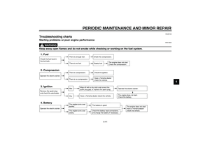
EAU25870
Troubleshooting
Although Yamaha motorcycles receive
a thorough inspection before shipment
from the factory, trouble may occur dur-
ing operation. Any problem in the fuel,
compression, or ignition systems, for
example, can cause poor starting and
loss of power.
The following troubleshooting charts
represent quick and easy procedures
for checking these vital systems your-
self. However, should your motorcycle
require any repair, take it to a Yamaha
dealer, whose skilled technicians have
the necessary tools, experience, and
know-how to service the motorcycle
properly.
Use only genuine Yamaha replace-
ment parts. Imitation parts may look like
Yamaha parts, but they are often inferi-
or, have a shorter service life and can
lead to expensive repair bills.