Page 25 of 96
, then at 5000 km (3000 mi)
and every 5000 km (3000 mi) th")
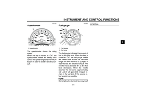
INSTRUMENT AND CONTROL FUNCTIONS
3-9
2
34
5
6
7
8
9 Oil change indicator “OIL”
This indicator flashes at the initial 1000
km (600 mi), then at 5000 km (3000 mi)
and every 5000 km (3000 mi) thereafter
to indicate that the engine oil should be
changed.
After changing the engine oil, reset the
oil change indicator. To reset the oil
change indicator, select it by pushing
the “SELECT” button until “OIL Trip” is
displayed, and then push the “RESET”
button at least 1 second. When pushing
the “RESET” button, “OIL Trip” starts
flashing. While “OIL Trip” is flashing,
push the “RESET” button for at least 3
seconds.
If the engine oil is changed before theoil change indicator “OIL” flashes (i.e.
before the periodic oil change interval
has been reached), the indicator “OIL”
must be reset after the oil change for
the next periodic oil change to be indi-
cated at the correct time.
The electrical circuit of the indicator can
be checked according to the following
procedure.
1. Set the engine stop switch to “”
and turn the key to “ON”.
2. Check that the oil change indicator
comes on for a few seconds and
then goes off.
3. If the oil change indicator does not
come on, have a Yamaha dealer
check the electrical circuit.
V-belt replacement indicator
“V-BELT”
This indicator flashes every 20000 km
(12500 mi) when the V-belt needs to be
replaced.
After changing the V-belt, reset the
V-belt replacement indicator. To reset
the V-belt replacement indicator, select
it by pushing the “SELECT” button until
“V-BELT Trip” is displayed, and then
push the “RESET” button at least 1 sec-
ond. When pushing the “RESET” but-
ton, “V-BELT Trip” starts flashing.
While “V-BELT Trip” is flashing, push
the “RESET” button for at least 3 sec-
onds.
If the V-belt is changed before the
1. Oil change indicator “OIL”
1
1. V-belt replacement indicator “V-BELT”
1
Page 26 of 96
, the
indicator “V-BE")
INSTRUMENT AND CONTROL FUNCTIONS
3-10
1
2
3
4
5
6
7
8
9
V-belt replacement indicator “V-BELT”
flashes (i.e. before the periodic V-belt
change interval has been reached), the
indicator “V-BELT” must be reset after
the V-belt change for the next periodic
V-belt change to be indicated at the
correct time.
The electrical circuit of the indicator can
be checked according to the following
procedure.
1. Turn the key to “ON” and make
sure that the engine stop switch is
set to “”.
2. If the V-belt replacement indicator
does not come on, have a Yamaha
dealer check the electrical circuit.
Self-diagnosis device
This model is equipped with a self-diag-
nosis device for various electrical cir-
cuits.
If any of those circuits are defective, the
engine trouble warning light will come
on, and then the display will indicate a
two-digit error code.
This model is also equipped with a
self-diagnosis device for the immobiliz-
er system.
If any of the immobilizer system circuits
are defective, the immobilizer system
indicator light will flash, and then the
display will indicate a two-digit error
code.
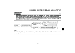
NOTE:
If the display indicates error code 52,
this could be caused by transponder in-
terference. If this error code appears,
try the following.
1. Use the code re-registering key to
start the engine.
NOTE:
Make sure there are no other immobi-
lizer keys close to the main switch, and
do not keep more than one immobilizer
key on the same key ring! Immobilizersystem keys may cause signal interfer-
ence, which may prevent the engine
from starting.
2. If the engine starts, turn it off and
try starting the engine with the
standard keys.
3. If one or both of the standard keys
do not start the engine, take the
vehicle, the code re-registering
key and both standard keys to a
Yamaha dealer and have the stan-
dard keys re-registered.
If the display indicates any error codes,
note the code number, and then have a
Yamaha dealer check the vehicle.
CAUTION:
ECA11590
If the display indicates an error
code, the vehicle should be checked
as soon as possible in order to avoid
engine damage.
1. Error code display
1
Page 27 of 96
INSTRUMENT AND CONTROL FUNCTIONS
3-11
2
34
5
6
7
8
9
EAU12331
Anti-theft alarm (optional)
This model can be equipped with an
optional anti-theft alarm by a Yamaha
dealer. Contact a Yamaha dealer for
more information.
EAU12347
Handlebar switches
LeftRight
EAU12360
Pass switch “PASS”
Press this switch to flash the headlight.
EAU12400
Dimmer switch “/”
Set this switch to “” for the high
beam and to “” for the low beam.
EAU12460
Turn signal switch “/”
To signal a right-hand turn, push this
switch to “”. To signal a left-hand
turn, push this switch to “”. When re-
1. Pass switch “PASS”
2. Dimmer switch “/”
3. Turn signal switch “/”
4. Horn switch “”
1
2
3
4
1. Engine stop switch “/”
2. Hazard switch “”
3. Start switch “”
1
23
Page 28 of 96

INSTRUMENT AND CONTROL FUNCTIONS
3-12
1
2
3
4
5
6
7
8
9
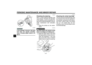
leased, the switch returns to the center
position. To cancel the turn signal
lights, push the switch in after it has re-
turned to the center position.
EAU12500
Horn switch “”
Press this switch to sound the horn.
EAU12660
Engine stop switch “/”
Set this switch to “” before starting
the engine. Set this switch to “” to
stop the engine in case of an emergen-
cy, such as when the vehicle overturns
or when the throttle cable is stuck.
EAU12720
Start switch “”
With the sidestand up, push this switch
while applying the front or rear brake to
crank the engine with the starter.
CAUTION:
ECA10050
See page 5-1 for starting instruc-
tions prior to starting the engine.
EAU42340
The engine trouble warning light and
ABS warning light will come on when
the key is turned to “ON” and the start
switch is pushed, but this does not indi-
cate a malfunction.
EAU12733
Hazard switch “”
With the key in the “ON” or “” posi-
tion, use this switch to turn on the haz-
ard lights (simultaneous flashing of all
turn signal lights).
The hazard lights are used in case of
an emergency or to warn other drivers
when your vehicle is stopped where it
might be a traffic hazard.
CAUTION:
ECA10061
Do not use the hazard lights for an
extended length of time with the en-
gine not running, otherwise the bat-
tery may discharge.
EAU44910
Front brake lever
The front brake lever is located at the
right handlebar grip. To apply the front
brake, pull this lever toward the handle-
bar grip.
The front brake lever is equipped with a
position adjusting dial. To adjust the
distance between the front brake lever
and the handlebar grip, turn the adjust-
ing dial while holding the front brake le-
ver pushed away from the handlebar
grip. Make sure that the appropriate
1. Front brake lever
2. Brake lever position adjusting dial
3. “” mark
4. Distance between brake lever and
handlebar grip
1
3
4 2
Page 29 of 96
INSTRUMENT AND CONTROL FUNCTIONS
3-13
2
34
5
6
7
8
9
setting on the adjusting dial is aligned
with the “” mark on the front brake le-
ver.
EAU44921
Rear brake lever
The rear brake lever is located at the
left handlebar grip. To apply the rear
brake, pull this lever toward the handle-
bar grip.
The rear brake lever is equipped with a
position adjusting dial. To adjust the
distance between the rear brake lever
and the handlebar grip, turn the adjust-
ing dial while holding the rear brake le-
ver pushed away from the handlebar
grip. Make sure that the appropriatesetting on the adjusting dial is aligned
with the “” mark on the rear brake le-
ver.
1. Rear brake lever
2. Brake lever position adjusting dial
3. “” mark
4. Distance between brake lever and
handlebar grip
1
3
42
Page 30 of 96

INSTRUMENT AND CONTROL FUNCTIONS
3-14
1
2
3
4
5
6
7
8
9
EAU12962
Rear brake lock lever
This vehicle is equipped with a rear
brake lock lever to prevent the rear
wheel from moving while stopped at
traffic signals, railroad crossings, etc.
To lock the rear wheel
Push the rear brake lock lever to the left
until it snaps into place.
To unlock the rear wheel
Push the rear brake lock lever back to
the original position.
NOTE:
�
Be sure to check that the rear
wheel does not move when therear brake lock lever is applied.
�
To provide secure locking of the
rear wheel, apply the rear brake le-
ver first before moving the rear
brake lock lever to the left.
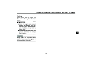
WARNING
EWA12361
Never move the rear brake lock lever
to the left while the vehicle is mov-
ing, otherwise loss of control or an
accident may result. Make sure that
the vehicle is stopped before mov-
ing the rear brake lock lever to the
left.
EAU12993
ABS (for ABS models)
The Yamaha ABS (Anti-lock Brake
System) features a dual electronic con-
trol system, which acts on the front and
rear brakes independently. The ABS
securely controls wheel lockup during
emergency braking on changing road
surfaces and under various weather
conditions, thereby maximizing tire ad-
hesion and performance while provid-
ing a smooth braking action. The ABS
is monitored by an ECU (Electronic
Control Unit), which will have recourse
to manual braking if a malfunction oc-
curs.
WARNING
EWA10090
�
The ABS performs best on long
braking distances.
�
On certain (rough or gravel)
roads, the braking distance may
be longer with than without the
ABS. Therefore, always keep a
sufficient distance to the vehi-
cle ahead to match the riding
speed.
1. Rear brake lock lever
1
Page 31 of 96

INSTRUMENT AND CONTROL FUNCTIONS
3-15
2
34
5
6
7
8
9
NOTE:
�
The ABS performs a self-diagno-
sis test for a few seconds each
time the vehicle first starts off after
the main switch was turned on.
During this test, a “clicking” noise
can be heard from the front of the
vehicle, and if either brake lever is
even slightly applied, a vibration
can be felt at the lever, but these
do not indicate a malfunction.
�
When the ABS is activated, the
brakes are operated in the usual
way. A pulsating action may be felt
at the brake levers, but this does
not indicate a malfunction.
�
This ABS has a test mode which
allows the owner to experience the
pulsating at the brake levers when
the ABS is operating. However,
special tools are required, so
please consult your Yamaha deal-
er when performing this test.
CAUTION:
ECA16120
Keep any type of magnets (including
magnetic pick-up tools, magneticscrewdrivers, etc.) away from the
front and rear wheel hubs, otherwise
the magnetic rotors equipped in the
wheel hubs may be damaged, result-
ing in improper performance of the
ABS system.
EAU13174
Fuel tank cap
To remove the fuel tank cap
1. Open the lid by pulling the lever up.
2. Insert the key into the lock and turn
it clockwise. The lock will be re-
leased and the fuel tank cap can
be removed.
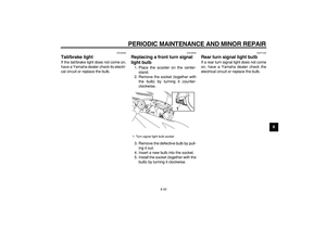
1. Front wheel hub
1. Rear wheel hub
11
1. Opening lever
2. Lid
1
2
Page 32 of 96
INSTRUMENT AND CONTROL FUNCTIONS
3-16
1
2
3
4
5
6
7
8
9To install the fuel tank cap
1. Align the match marks, insert the
fuel tank cap into the tank opening,
and then push down on the cap.
2. Turn the key counterclockwise to
the original position, and then re-move it.
3. Close the lid.
WARNING
EWA11260
Make sure that the fuel tank cap is
properly installed and locked in
place before riding the scooter.
EAU13211
Fuel
Make sure that there is sufficient fuel in
the tank. Fill the fuel tank to the bottom
of the filler tube as shown.
WARNING
EWA10880
�
Do not overfill the fuel tank, oth-
erwise it may overflow when the
fuel warms up and expands.
�
Avoid spilling fuel on the hot en-
gine.
CAUTION:
ECA10070
Immediately wipe off spilled fuel
with a clean, dry, soft cloth, since
1. Fuel tank cap
1. Match marks
1
1
1. Fuel tank filler tube
2. Fuel level
21


This model can be equipped with an
optional anti-theft alarm by a Yamaha
dealer. Contact a Yamaha dea")

