Page 17 of 96

3-1
2
34
5
6
7
8
9
INSTRUMENT AND CONTROL FUNCTIONS
EAU10974
Immobilizer system
This vehicle is equipped with an immo-
bilizer system to help prevent theft by
re-registering codes in the standard
keys. This system consists of the fol-
lowing.
�
a code re-registering key (with a
red bow)
�
two standard keys (with a black
bow) that can be re-registered with
new codes
�
a transponder (which is installed in
the code re-registering key)
�
an immobilizer unit
�
an ECU (Electronic Control Unit)
�
an immobilizer system indicator
light (See page 3-3.)
The key with the red bow is used to reg-
ister codes in each standard key. Since
re-registering is a difficult process, take
the vehicle along with all three keys to
a Yamaha dealer to have them re-reg-
istered. Do not use the key with the red
bow for driving. It should only be used
for re-registering the standard keys. Al-
ways use a standard key for driving.
CAUTION:
ECA11821
�
DO NOT LOSE THE CODE
RE-REGISTERING KEY! CON-
TACT YOUR DEALER IMMEDI-
ATELY IF IT IS LOST! If the code
re-registering key is lost, regis-
tering new codes in the stan-
dard keys is impossible. The
standard keys can still be used
to start the vehicle, however if
code re-registering is required
(i.e., if a new standard key is
made or all keys are lost) the en-
tire immobilizer system must be
replaced. Therefore, it is highly
recommended to use either
standard key and keep the codere-registering key in a safe
place.
�
Do not submerse any key in wa-
ter.
�
Do not expose any key to exces-
sively high temperatures.
�
Do not place any key close to
magnets (this includes, but not
limited to, products such as
speakers, etc.).
�
Do not place items that transmit
electrical signals close to any
key.
�
Do not place heavy items on any
key.
�
Do not grind any key or alter its
shape.
�
Do not disassemble the plastic
part of any key.
�
Do not put two keys of any im-
mobilizer system on the same
key ring.
�
Keep the standard keys as well
as keys of other immobilizer
systems away from this vehi-
cle’s code re-registering key.
�
Keep other immobilizer system
keys away from the main switch
1. Code re-registering key (red bow)
2. Standard keys (black bow)
Page 18 of 96

INSTRUMENT AND CONTROL FUNCTIONS
3-2
1
2
3
4
5
6
7
8
9as they may cause signal inter-
ference.
EAU10471
Main switch/steering lock
The main switch/steering lock controls
the ignition and lighting systems, and is
used to lock the steering.
NOTE:
Be sure to use the standard key (black
bow) for regular use of the vehicle. To
minimize the risk of losing the code
re-registering key (red bow), keep it in a
safe place and only use it for code
re-registering.
EAU34121
ON
All electrical circuits are supplied with
power; the meter lighting, taillight, li-
cense plate light and auxiliary lightscome on, and the engine can be start-
ed. The key cannot be removed.
NOTE:
The headlights come on automatically
when the engine is started and stay on
until the key is turned to “OFF” or the
sidestand is moved down.
EAU10660
OFF
All electrical systems are off. The key
can be removed.
EAU10680
LOCK
The steering is locked, and all electrical
systems are off. The key can be re-
moved.
To lock the steering
1. Turn the handlebars all the way to
the left.
2. Push the key in from the “OFF” po-
sition, and then turn it to “LOCK”
while still pushing it.
3. Remove the key.
Page 19 of 96

INSTRUMENT AND CONTROL FUNCTIONS
3-3
2
34
5
6
7
8
9
To unlock the steering
Push the key in, and then turn it to
“OFF” while still pushing it.
WARNING
EWA10060
Never turn the key to “OFF” or
“LOCK” while the vehicle is moving,
otherwise the electrical systems will
be switched off, which may result in
loss of control or an accident. Make
sure that the vehicle is stopped be-
fore turning the key to “OFF” or
“LOCK”.
EAU10941
(Parking)
The steering is locked, and the taillight,
license plate light and auxiliary lights
are on. The hazard lights and turn sig-
nal lights can be turned on, but all other
electrical systems are off. The key can
be removed.
The steering must be locked before the
key can be turned to “ ”.
CAUTION:
ECA11020
Do not use the parking position for
an extended length of time, other-
wise the battery may discharge.
EAU11003
Indicator and warning lights
EAU11030
Turn signal indicator lights “” and
“”
The corresponding indicator light flash-
es when the turn signal switch is
pushed to the left or right.
EAU11080
High beam indicator light “”
This indicator light comes on when the
1. Turn signal indicator lights “ ” and “ ”
2. High beam indicator light “ ”
3. Anti-lock Brake System (ABS) warning
light “ ”
4. Immobilizer system indicator light
5. Engine trouble warning light “ ”
1
3
1
2
4
5
ABS
Page 20 of 96

INSTRUMENT AND CONTROL FUNCTIONS
3-4
1
2
3
4
5
6
7
8
9
high beam of the headlight is switched
on.
EAU43020
Engine trouble warning light “”
This warning light comes on when an
electrical circuit monitoring the engine
is defective. When this occurs, have a
Yamaha dealer check the self-diagno-
sis system.
The electrical circuit of the warning light
can be checked by turning the key to
“ON”. If the warning light does not come
on for a few seconds, then go off, have
a Yamaha dealer check the electrical
circuit.
NOTE:
This warning light will come on when
the key is turned to “ON” and the start
switch is pushed, but this does not indi-
cate a malfunction.
EAU43030
ABS warning light “” (for ABS
models)
CAUTION:
ECA10830
If the ABS warning light comes on orflashes while riding, the ABS may be
defective. If this occurs, have a
Yamaha dealer check the electrical
circuit.
See page 3-14 for an explanation of the
ABS.
The electrical circuit of the warning light
can be checked by setting the engine
stop switch to “” and turning the key
to “ON”. The warning light should come
on for a few seconds, and then go off. If
the warning light does not come on or
remains on, have a Yamaha dealer
check the electrical circuit.
WARNING
EWA11350
When the ABS warning light comes
on or flashes while riding, the brake
system reverts to conventional brak-
ing. Therefore, be careful not to
cause the wheel to lock during emer-
gency braking.
NOTE:
The ABS warning light may come on
while accelerating the engine with the
scooter on its centerstand, but this
does not indicate a malfunction.
EAU38620
Immobilizer system indicator light
The electrical circuit of the indicator
light can be checked by turning the key
to “ON”.
If the indicator light does not come on
for a few seconds, then go off, have a
Yamaha dealer check the electrical cir-
cuit.
When the key is turned to “OFF” and 30
seconds have passed, the indicator
light will start flashing indicating the im-
mobilizer system is enabled. After 24
hours have passed, the indicator light
will stop flashing, however the immobi-
lizer system is still enabled.
This model is also equipped with a
self-diagnosis device for the immobiliz-
er system. (See page 3-10 for an expla-
nation of the self-diagnosis device.)
ABS
Page 21 of 96
INSTRUMENT AND CONTROL FUNCTIONS
3-5
2
34
5
6
7
8
9
EAU11601
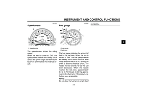
Speedometer
The speedometer shows the riding
speed.
When the key is turned to “ON”, the
speedometer needle will sweep once
across the speed range and then return
to zero in order to test the electrical cir-
cuit.
EAU44981
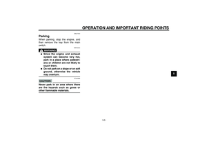
Fuel gauge
The fuel gauge indicates the amount of
fuel in the fuel tank. When the key is
turned to “ON”, the fuel gauge needle
will sweep once across the fuel level
range and then return to “E” (Empty) in
order to test the electrical circuit. The
needle moves towards “E” as the fuel
level decreases. When the needle
reaches the red zone, approximately
3.0 L (0.79 US gal) (0.66 Imp.gal) re-
main in the fuel tank. If this occurs, re-
fuel as soon as possible.
NOTE:
Do not allow the fuel tank to empty itself
completely.
1. Speedometer
1
1. Fuel gauge
2. Red zone
1
2
Page 22 of 96
INSTRUMENT AND CONTROL FUNCTIONS
3-6
1
2
3
4
5
6
7
8
9
EAU12181
Coolant temperature gauge
With the key in the “ON” position, the
coolant temperature gauge indicates
the temperature of the coolant. When
the key is turned to “ON”, the coolant
temperature gauge needle will sweep
once across the temperature range and
then return to “C” in order to test the
electrical circuit. The coolant tempera-
ture varies with changes in the weather
and engine load. If the needle reaches
or enters the red zone, stop the vehicle
and let the engine cool. (See
page 6-35.)
CAUTION:
ECA10020
Do not operate the engine if it is
overheated.
EAU44963
Multi-function display
WARNING
EWA12311
Be sure to stop the vehicle before
making any setting changes to the
multi-function display.
1. Coolant temperature gauge
2. Red zone
2
1
1. Tachometer
2. Tachometer red zone
3. V-belt replacement indicator “V-BELT”
4. Odometer/tripmeters
1
2
3
4
Page 23 of 96

�
an odometer (which shows the to-
t")
INSTRUMENT AND CONTROL FUNCTIONS
3-7
2
34
5
6
7
8
9
The multi-function display is equipped
with the following:
�
a tachometer (which shows engine
speed)
�
an odometer (which shows the to-
tal distance traveled)
�
two tripmeters (which show the
distance traveled since they were
last set to zero)
�
a fuel reserve tripmeter (which
shows the distance traveled when
the remaining fuel in the fuel tank
reaches approximately 3.0 L (0.79
US gal) (0.66 Imp.gal))
�
a self-diagnosis device
�
a clock
�
an oil change tripmeter (which
shows the distance traveled since
the last engine oil change)
�
a V-belt replacement tripmeter
(which shows the distance trav-
eled since the last V-belt replace-
ment)
NOTE:
�
Be sure to turn the key to “ON” be-
fore using the “SELECT” and
“RESET” buttons.
�
When the key is turned to “ON”, all
of the display segments of the
multi-function display will appear
one after the other and then disap-
pear, in order to test the electrical
circuits.
Tachometer
The tachometer allows the rider to
monitor the engine speed and keep it
within the ideal power range.
CAUTION:
ECA10031
Do not operate the engine in the ta-
chometer red zone.
Red zone: 8250 r/min and above
Clock
To set the clock:
1. Push the “SELECT” button and
“RESET” button together for at
least two seconds.
2. When the hour digits start flashing,
push the “RESET” button to set the
hours.
3. Push the “SELECT” button, and
the minute digits will start flashing.
4. Push the “RESET” button to set
the minutes.
5. Push the “SELECT” button and
then release it to start the clock.
1. Clock
2. Oil change indicator “OIL”
1. “RESET” button
2. “SELECT” button
1
2
1
2
Page 24 of 96

INSTRUMENT AND CONTROL FUNCTIONS
3-8
1
2
3
4
5
6
7
8
9Odometer and tripmeter modes
Pushing the “SELECT” button switches
the display between the odometer
mode and the tripmeter modes in the
following order:
Odo
→
Trip-A
→
Trip-B
→
OIL Trip
→
V-BELT Trip
→
Odo
When approximately 3.0 L (0.79 US
gal) (0.66 Imp.gal) of fuel remains in the
fuel tank, the display will automatically
change to the fuel reserve tripmeter
mode “F Trip” and start counting the
distance traveled from that point. In that
case, pushing the “SELECT” button
switches the display between the vari-
ous tripmeter and odometer modes in
the following order:
Odo
→
F Trip
→
Trip-A
→
Trip-B
→
OILTrip
→
V-BELT Trip
→
Odo
To reset a tripmeter, select it by push-
ing the “SELECT” button until “F Trip”,
“Trip-A” or “Trip-B” is displayed. While
“F Trip”, “Trip-A” or “Trip-B” is dis-
played, push the “RESET” button for at
least one second. If you do not reset
the fuel reserve tripmeter manually, it
will reset itself automatically and the
display will return to the prior mode af-
ter refueling and traveling 5 km (3 mi).
NOTE:
The display cannot be changed back to
“F Trip” after pushing the “RESET” but-
ton.
1. Odometer/tripmeters
1. Oil change tripmeter
1
1
1. V-belt replacement tripmeter
1
1. Fuel reserve tripmeter
1