Page 57 of 78
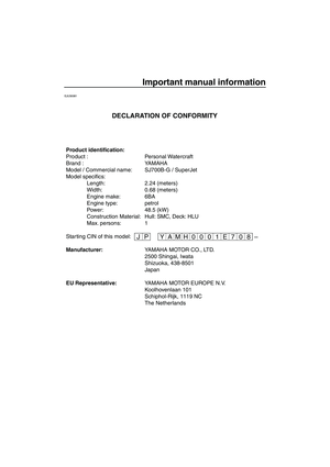
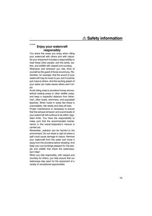
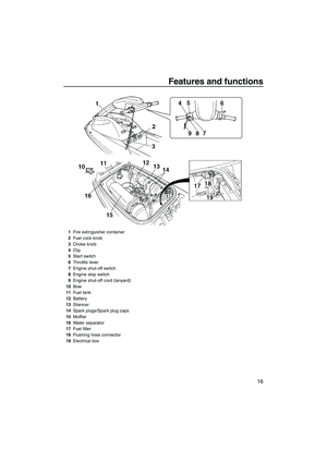
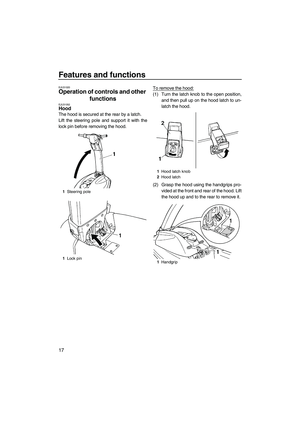
Maintenance and care
50
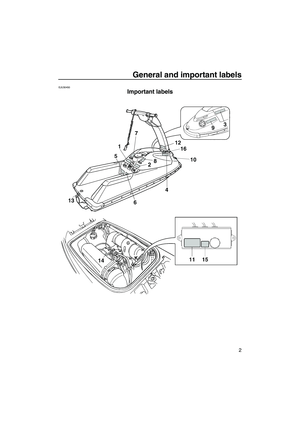
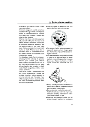
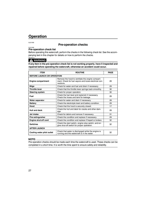
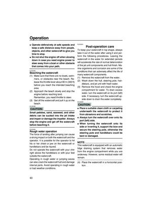
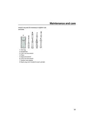
wrench may also be necessary to tighten nuts
and bolts.
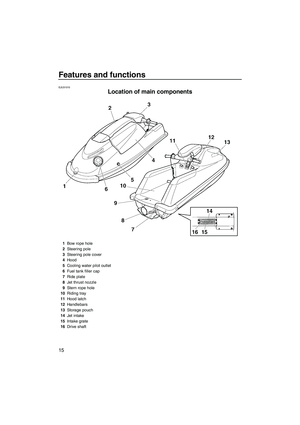
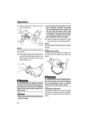
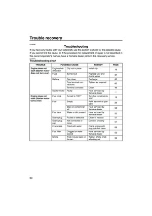
1Tool bag
2Screwdriver
314/21 mm box wrench
4Pliers
5Open-end wrench
610/12 mm box wrench
7Garden hose adapter
8Spark plug (one included for each cylinder)
UF2F70E0.book Page 50 Tuesday, April 17, 2007 9:56 AM
Page 58 of 78

Maintenance and care
51
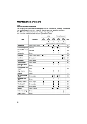
EJU33820Periodic maintenance chart
The following chart gives general guidelines for periodic maintenance. However, maintenance
may need to be performed more frequently depending on your operating conditions.
This “” mark indicates maintenance that you may do yourself.
This “” mark indicates work to be done by a Yamaha dealer.
Item OperationInitial Thereafter every
Page 10
hours50
hours100
hours100
hours200
hours
6
months12
months12
months24
months
Spark plugsCheck, clean, adjust 57
Lubrication pointsLubricate 58
Intermediate hous-
ingLubricate 58
Fuel systemCheck 53
Fuel filterCheck, clean, replace 53
Fuel tankCheck, clean 53
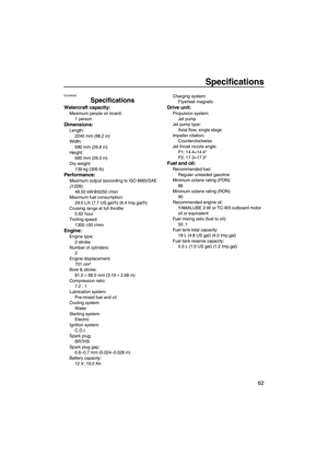
CarburetorCheck, adjust 61
Trolling speedCheck, adjust 61
Carburetor throt-
tle shaftCheck—
Cooling water pas-
sagesFlush
*46
Bilge strainerClean—
ImpellerCheck—
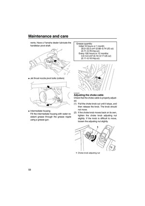
Jet thrust nozzle
angleCheck, adjust 53
Handlebar pivot
shaftCheck—
Steering frictionCheck, adjust 54
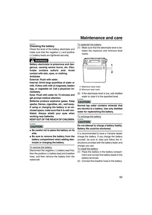
Throttle cableCheck, adjust 56
Choke cableCheck, adjust 59
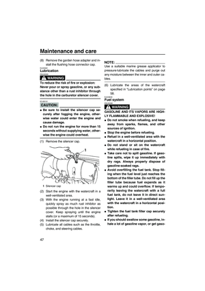
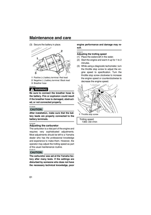
BatteryCheck, charge 60
Rubber couplingCheck—
Engine mountCheck—
UF2F70E0.book Page 51 Tuesday, April 17, 2007 9:56 AM
Page 59 of 78
Maintenance and care
52
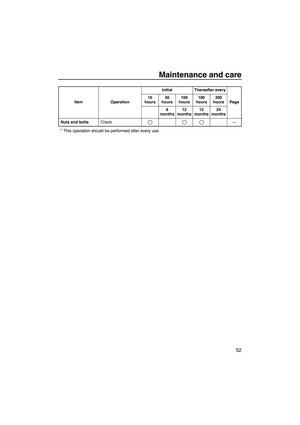
* This operation should be performed after every use.
Nuts and boltsCheck— Item OperationInitial Thereafter every
Page 10
hours50
hours100
hours100
hours200
hours
6
months12
months12
months24
months
UF2F70E0.book Page 52 Tuesday, April 17, 2007 9:56 AM
Page 60 of 78

Maintenance and care
53
EJU34201Checking the fuel system
WARNING
EWJ00370
Gasoline is highly flammable and explo-
sive. Failure to check for and repair any
fuel leakage could result in a fire or explo-
sion. A fire or explosion can cause severe
injury or death. Shut the engine off. Do not
smoke. Avoid spilling gasoline.
Check the fuel system for leaks, cracks, and
malfunctions. If any problem is found, do the
necessary repair or replacement as required.
If repair is necessary, consult a Yamaha deal-
er.
Check:
�Carburetor for leakage.
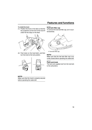
�Fuel tank filler cap and seal for damage.
�Fuel in fuel tank for water and dirt.
�Fuel tank for damage, cracks, and leakage.
�Fuel hoses and joints for damage, cracks,
and leakage.
�Fuel filter for leakage.
�Fuel cock for leakage.
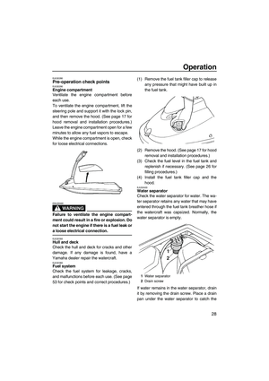
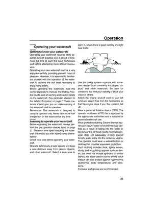
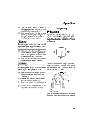
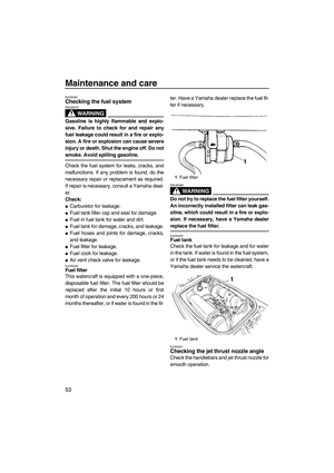
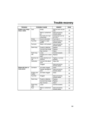
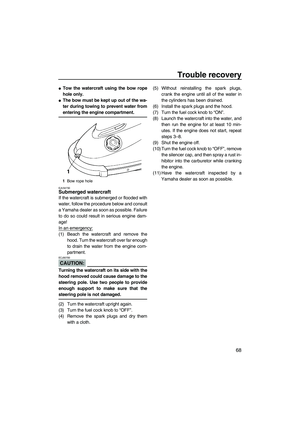
�Air vent check valve for leakage.EJU34220Fuel filter
This watercraft is equipped with a one-piece,
disposable fuel filter. The fuel filter should be
replaced after the initial 10 hours or first
month of operation and every 200 hours or 24
months thereafter, or if water is found in the fil-ter. Have a Yamaha dealer replace the fuel fil-
ter if necessary.
WARNING
EWJ00360
Do not try to replace the fuel filter yourself.
An incorrectly installed filter can leak gas-
oline, which could result in a fire or explo-
sion. If necessary, have a Yamaha dealer
replace the fuel filter.
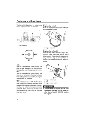
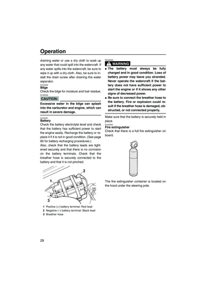
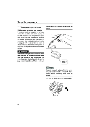
EJU34230Fuel tank
Check the fuel tank for leakage and for water
in the tank. If water is found in the fuel system,
or if the fuel tank needs to be cleaned, have a
Yamaha dealer service the watercraft.
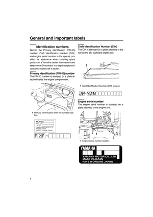
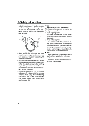
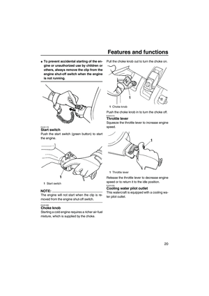
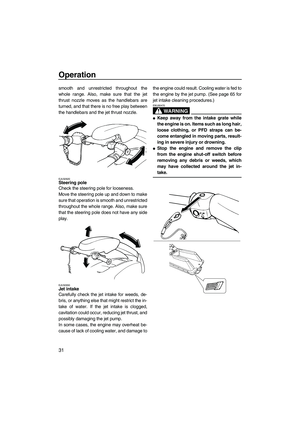
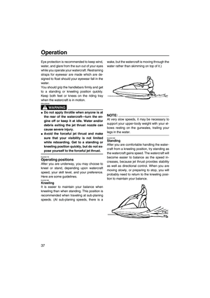
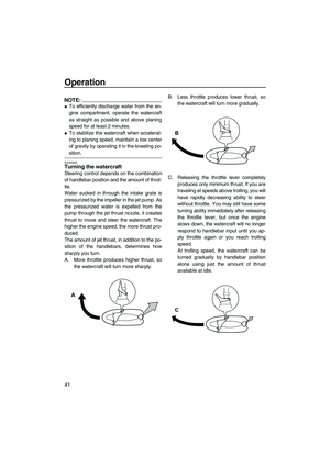
EJU34321Checking the jet thrust nozzle angle
Check the handlebars and jet thrust nozzle for
smooth operation.
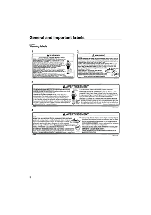
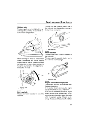
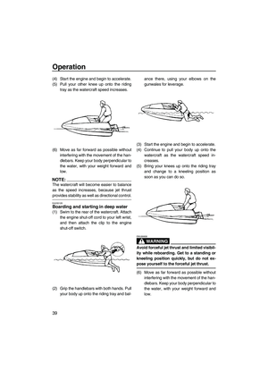
1Fuel filter
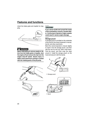
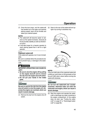
1Fuel tank
UF2F70E0.book Page 53 Tuesday, April 17, 2007 9:56 AM
Page 61 of 78
Maintenance and care
54
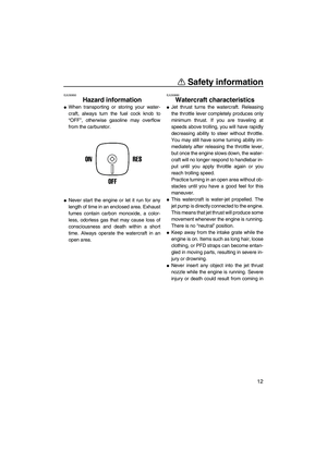
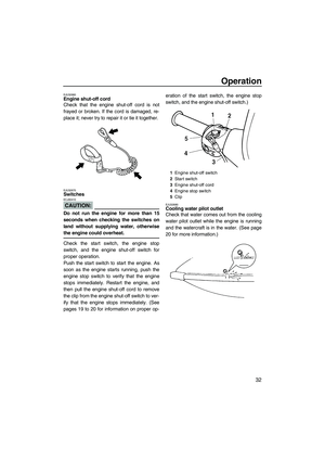
Turn the handlebars as far as possible to the
right and left and check that the difference of
distances A and B between the jet thrust noz-
zle and the nozzle is within specification.
If the steering is stiff or misadjusted, have a
Yamaha dealer service it.
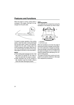
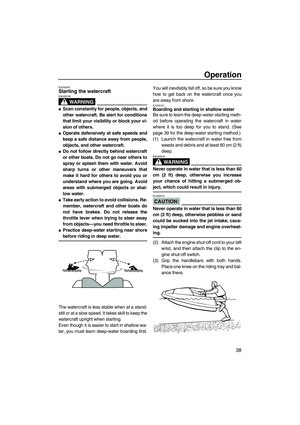
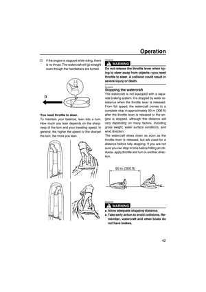
EJU34331Adjusting the steering friction
The amount of friction in the steering can be
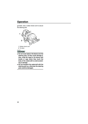
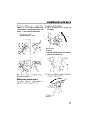
adjusted to suit operator preference.To adjust the steering friction:
(1) Lift the steering pole and support it with
the lock pin.
(2) Remove the four screws, and then re-
move the handlebar cover.
(3) Turn the handlebars so that the left han-
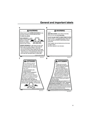
dlebar grip is facing down. Difference of A and B:
Maximum 5 mm (0.20 in)
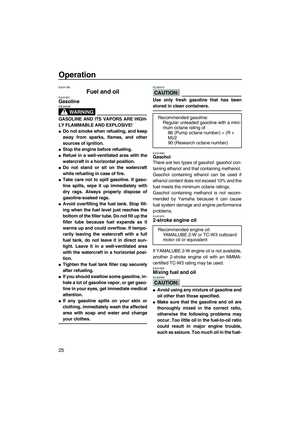
1Steering pole
2Lock pin
1Adjusting nut
2Locknut
UF2F70E0.book Page 54 Tuesday, April 17, 2007 9:56 AM
Page 62 of 78
 Loosen the locknut.
(5) Tighten or loosen the adjusting nut until
the desired amount of friction is obtained.
(6) Hold the adjusting nut with one wrench
while tightening th")
Maintenance and care
55
(4) Loosen the locknut.
(5) Tighten or loosen the adjusting nut until
the desired amount of friction is obtained.
(6) Hold the adjusting nut with one wrench
while tightening the locknut with another
wrench.
(7) Install the handlebar cover and the four
screws.
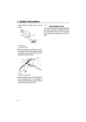
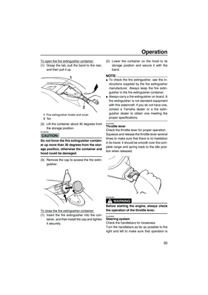
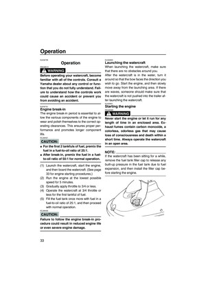
EJU31282Adjusting the jet thrust nozzle angle
The angle of the jet thrust nozzle can be ad-
justed to suit operator preference according to
the following procedure.
To change the steering cable pivot bolt posi-
tion:
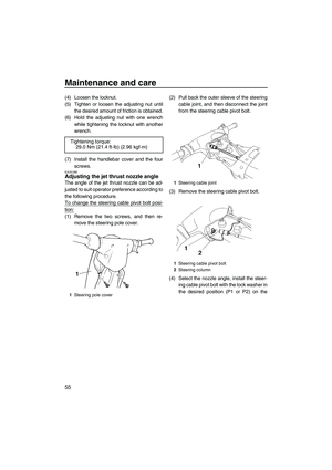
(1) Remove the two screws, and then re-
move the steering pole cover.(2) Pull back the outer sleeve of the steering
cable joint, and then disconnect the joint
from the steering cable pivot bolt.
(3) Remove the steering cable pivot bolt.
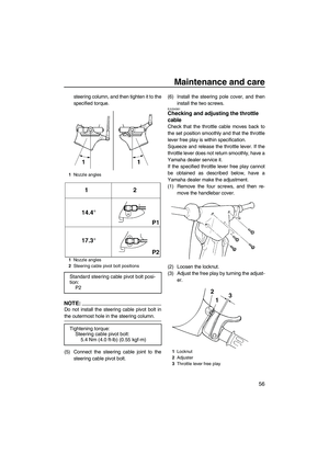
(4) Select the nozzle angle, install the steer-
ing cable pivot bolt with the lock washer in
the desired position (P1 or P2) on the Tightening torque:
29.0 Nm (21.4 ft-lb) (2.96 kgf-m)
1Steering pole cover
1Steering cable joint
1Steering cable pivot bolt
2Steering column
UF2F70E0.book Page 55 Tuesday, April 17, 2007 9:56 AM
Page 63 of 78
 Connect the s")
Maintenance and care
56
steering column, and then tighten it to the
specified torque.
NOTE:
Do not install the steering cable pivot bolt in
the outermost hole in the steering column.
(5) Connect the steering cable joint to the
steering cable pivot bolt.(6) Install the steering pole cover, and then
install the two screws.
EJU34361Checking and adjusting the throttle
cable
Check that the throttle cable moves back to
the set position smoothly and that the throttle
lever free play is within specification.
Squeeze and release the throttle lever. If the
throttle lever does not return smoothly, have a
Yamaha dealer service it.
If the specified throttle lever free play cannot
be obtained as described below, have a
Yamaha dealer make the adjustment.
(1) Remove the four screws, and then re-
move the handlebar cover.
(2) Loosen the locknut.
(3) Adjust the free play by turning the adjust-
er.
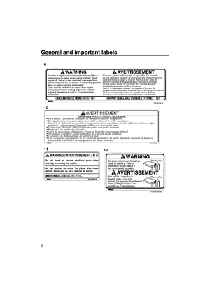
1Nozzle angles
1Nozzle angles
2Steering cable pivot bolt positions
Standard steering cable pivot bolt posi-
tion:
P2
Tightening torque:
Steering cable pivot bolt:
5.4 Nm (4.0 ft-lb) (0.55 kgf-m)
1Locknut
2Adjuster
3Throttle lever free play
UF2F70E0.book Page 56 Tuesday, April 17, 2007 9:56 AM
Page 64 of 78
 Hold the adjuster with one wrench while
tightening the locknut with another
wrench.
(5) Install the handlebar cover and the four
screws.
EJU34371Cleaning and adjusting the")
Maintenance and care
57
(4) Hold the adjuster with one wrench while
tightening the locknut with another
wrench.
(5) Install the handlebar cover and the four
screws.
EJU34371Cleaning and adjusting the spark
plugs
WARNING
EWJ00350
Be careful not to damage the insulator
when removing or installing a spark plug.
A damaged insulator could allow sparks to
escape, which could result in a fire or ex-
plosion.
The spark plug is an important engine compo-
nent and is easy to inspect. The condition of
the spark plug can indicate something about
the condition of the engine. For example, if the
center electrode porcelain is very white, this
could indicate an intake air leak or carburetion
problem in that cylinder. Do not attempt to di-
agnose any problems yourself. Have a
Yamaha dealer service the watercraft.
Remove and inspect the spark plugs periodi-
cally; heat and deposits will cause the spark
plugs to slowly break down and erode. If elec-
trode erosion becomes excessive, or if carbon
and other deposits are excessive, replace the
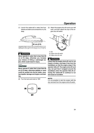
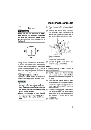
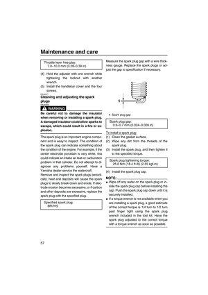
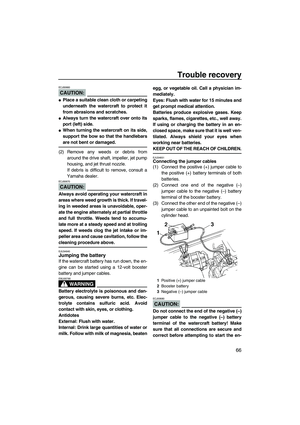
spark plug with the specified plug.Measure the spark plug gap with a wire thick-
ness gauge. Replace the spark plugs or ad-
just the gap to specification if necessary.
To install a spark plug:(1) Clean the gasket surface.
(2) Wipe any dirt from the threads of the
spark plug.
(3) Install the spark plug, and then tighten it
to the specified torque.
(4) Install the spark plug cap.
NOTE:
�Wipe off any water on the spark plug or in-
side the spark plug cap before installing the
cap. Push the spark plug cap down until it is
securely installed.
�If a torque wrench is not available when you
are installing a spark plug, a good estimate
of the correct torque is 1/4 turn to 1/2 turn
past finger tight using the spark plug
wrench included in the tool kit. Have the
spark plug adjusted to the correct torque
with a torque wrench as soon as possible.
Throttle lever free play:
7.0–10.0 mm (0.28–0.39 in)
Specified spark plug:
BR7HS
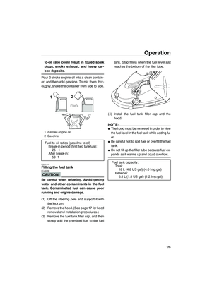
1Spark plug gap
Spark plug gap:
0.6–0.7 mm (0.024–0.028 in)
Spark plug tightening torque:
25.0 Nm (18.4 ft-lb) (2.55 kgf-m)
UF2F70E0.book Page 57 Tuesday, April 17, 2007 9:56 AM