Page 80 of 468

4-11
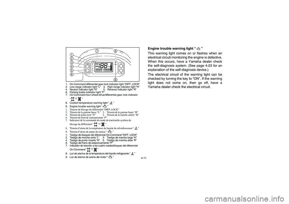
1. On-Command differential gear lock indicator light “DIFF. LOCK”
2. Low-range indicator light “L”3. High-range indicator light “H”
4. Neutral indicator light “N”5. Reverse indicator light “R”
6. Parking brake indicator light “P”
7. On-Command four-wheel-drive/differential gear lock indicator
“”/“”
8. Coolant temperature warning light “”
9. Engine trouble warning light “”
1. Témoin de blocage du différentiel “DIFF. LOCK”
2. Témoin de la gamme basse “L”3. Témoin de la gamme haute “H”
4. Témoin de point mort “N”5. Témoin de la marche arrière “R”
6. Témoin du frein de stationnement “P”
7. Indicateur de la commande du mode de traction/du système de
blocage du différentiel “”/“”
8. Témoin d’alerte de la température du liquide de refroidissement “”
9. Témoin d’alerte de panne du moteur “”
1. Testigo de bloqueo del diferencial On-Command “DIFF. LOCK”
2. Testigo de marcha corta “L”3. Testigo de marcha larga “H”
4. Testigo de punto muerto “N”5. Testigo de marcha atrás “R”
6. Testigo del freno de estacionamiento “P”
7. Indicador de tracción a las cuatro ruedas/bloqueo del diferencial
On-Command “”/“”
8. Luz de alarma de la temperatura del líquido refrigerante “”
9. Luz de alarma de avería del motor “”
1
2
3
4
5
6
8
9 7
km/h
DIFF.
LOCK
DIFF.
LOCK
DIFF.
LOCK
5B410003
Engine trouble warning light “”
This warning light comes on or flashes when an
electrical circuit monitoring the engine is defective.
When this occurs, have a Yamaha dealer check
the self-diagnosis system. (See page 4-23 for an
explanation of the self-diagnosis device.)
The electrical circuit of the warning light can be
checked by turning the key to “ON”. If the warning
light does not come on, then go off, have a
Yamaha dealer check the electrical circuit.
EE.book Page 11 Monday, October 8, 2007 4:48 PM
Page 90 of 468
4-21 1. Fuel level warning indicator
2. Fuel meter 3.“E” segment
1. Indicateur d’alerte du niveau de carburant
2. Afficheur du niveau de carburant
3. Segment “E”
1. Indicador de alarma del nivel de combustible
2. Indicador de combustible 3. Segmento “E”
1
2
3
km/h
Fuel meter
The fuel meter indicates the amount of fuel in the
fuel tank. The display segments of the fuel meter
disappear from “F” (full) towards “E” (empty) as the
fuel level decreases. When the “E” segment disap-
pears and the fuel level warning indicator flashes,
refuel as soon as possible.TIP
This fuel meter is equipped with a self-diagnosis
system. If the electrical circuit is defective, all the
display segments and fuel level warning indicator
will start flashing. If this occurs, have a Yamaha
dealer check the electrical circuit.
EE.book Page 21 Monday, October 8, 2007 4:48 PM
Page 92 of 468
4-23 1. Error code display
1. Afficheur des codes d’erreur
1. Indicación de códigos de error
1
km/h
Self-diagnosis device
This model is equipped with a self-diagnosis de-
vice for various electrical circuits.
If any of those circuits are defective, the engine
trouble warning light will come on or flash, and
then the multi-function display will indicate a two-
digit error code.
If the multi-function display indicates such an error
code, note the code number, and then have a
Yamaha dealer check the vehicle.NOTICE
If the multi-function display indicates an error
code, the vehicle should be checked as soon
as possible in order to avoid engine damage.
EE.book Page 23 Monday, October 8, 2007 4:48 PM
Page 106 of 468
4-37 1. Driver seat 2. Passenger seat
3. Seat lock lever (× 2)
1. Siège du conducteur 2. Siège du passager
3. Manette de verrouillage de siège (× 2)
1. Asiento del conductor 2. Asiento del pasajero
3. Palanca de bloqueo del asiento (× 2)
EVU00330
Seats
To remove a seat, pull its seat lock lever upward,
lift the front of the seat, and then slide the seat for-
ward and up.
To install a seat, insert the projections on the rear
of the seat into the seat holders and push down on
the seat at the front. Make sure the seats are se-
curely latched. WARNING! A loose seat could
cause the operator to lose control, or cause
the operator or passenger to fall.
EE.book Page 37 Monday, October 8, 2007 4:48 PM
Page 110 of 468
4-41 1. Storage/cup holder (× 1) 2. Cup holder (× 2)
1. Espace de rangement/porte-gobelet (× 1)
2. Porte-gobelet (× 2)
1. Portaobjetos/portavasos (× 1)
2. Portavasos (× 2)
2 1
5B410005
Cup holders
Be sure to tightly close the cap of any plastic bottle
before placing it in a cup holder.
Some plastic bottles may not fit into the cup hold-
ers depending on their size and shape.
WARNING
�
While the vehicle is moving, do not place
any open or glass containers in the cup
holders; otherwise, the contents may spill
and the glass containers may break.
�
Do not place any items, other than cups or
plastic bottles, in the cup holders; other-
wise, they may be thrown about and possi-
bly injure people in the vehicle during sud-
den braking or an accident.
EE.book Page 41 Monday, October 8, 2007 4:48 PM
Page 114 of 468
4-45 1. Cargo bed release lever
1. Levier de dégagement de la benne
1. Palanca de desbloqueo de la caja de carga
Lifting and lowering the cargo bed
To liftPush down the cargo bed release lever on the left
or right side of the vehicle, and then slowly lift up
the cargo bed until it stops.
To lowerWith hands and fingers clear of pinch points, lower
the cargo bed slowly to its original position and be
sure it is locked into place. WARNING! Keep
hands, body, and other people away from
pinch points when lowering bed. Do not hold
onto the cage/frame while closing the bed.
EE.book Page 45 Monday, October 8, 2007 4:48 PM
Page 116 of 468
4-47
5B410006
Front and rear shock absorber adjustment
The spring preload can be adjusted to suit the op-
erating conditions. You can reduce preload for a
softer ride, or increase preload if frequent bottom-
ing occurs or when carrying loads.
WARNING
Always adjust the shock absorbers on the left
and right sides to the same setting. Uneven ad-
justment can cause poor handling and loss of
stability, which could lead to an accident.NOTICE
Frequent or severe bottoming can cause in-
creased wear or damage to the vehicle.
The rear wheels need to be removed to adjust the
rear shock absorber assemblies. (See pages
8-111–8-117 for wheel removal and installation
procedures.)
EE.book Page 47 Monday, October 8, 2007 4:48 PM
Page 124 of 468

5-1
EVU01200
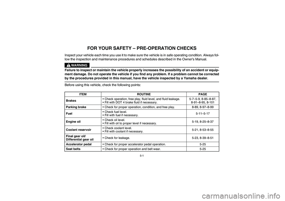
1 -FOR YOUR SAFETY – PRE-OPERATION CHECKS
Inspect your vehicle each time you use it to make sure the vehicle is in safe operating condition. Always fol-
low the inspection and maintenance procedures and schedules described in the Owner’s Manual.
WARNING
Failure to inspect or maintain the vehicle properly increases the possibility of an accident or equip-
ment damage. Do not operate the vehicle if you find any problem. If a problem cannot be corrected
by the procedures provided in this manual, have the vehicle inspected by a Yamaha dealer.Before using this vehicle, check the following points:
ITEM ROUTINE PAGE
BrakesCheck operation, free play, fluid level, and fluid leakage.
Fill with DOT 4 brake fluid if necessary.5-7–5-9, 8-85–8-87,
8-91–8-95, 8-101
Parking brakeCheck for proper operation, condition, and free play. 8-89, 8-97–8-99
FuelCheck fuel level.
Fill with fuel if necessary.5-11–5-17
Engine oilCheck oil level.
Fill with oil to proper level if necessary.5-19, 8-25–8-37
Coolant reservoirCheck coolant level.
Fill with coolant if necessary.5-21, 8-53–8-55
Final gear oil/
Differential gear oilCheck for leakage. 5-23, 8-39–8-51
Accelerator pedalCheck for proper accelerator pedal operation. 5-25
Seat beltsCheck for proper operation and belt wear. 5-25
EE.book Page 1 Monday, October 8, 2007 4:48 PM