Page 24 of 98

INSTRUMENT AND CONTROL FUNCTIONS
3-8
1
2
3
4
5
6
7
8
9
procedure.
1. Turn the key to “ON” and make
sure that the engine stop switch is
set to “”.
2. If the indicator does not come on,
have a Yamaha dealer check the
electrical circuit.
Self-diagnosis device
This model is equipped with a self-diag-
nosis device for various electrical cir-
cuits.
If any of those circuits are defective, the
multi-function display will indicate a
two-digit error code.
If the multi-function display indicates
such an error code, note the code num-
ber, and then have a Yamaha dealer
check the vehicle.
CAUTION:
ECA11790
If the multi-function display indi-
cates an error code, the vehicle
should be checked as soon as pos-
sible in order to avoid engine dam-
age.
This model is also equipped with a
self-diagnosis device for the immobiliz-er system.
If any of the immobilizer system circuits
are defective, the immobilizer system
indicator light will flash, and then the
multi-function display will indicate a
two-digit error code when the key is
turned to “ON”.
NOTE:
If the multi-function display indicates er-
ror code 52, this could be caused by
transponder interference. If this error
appears, try the following.
1. Use the code re-registering key to
start the engine.
NOTE:
Make sure there are no other immobi-
lizer keys close to the main switch, and
do not keep more than one immobilizer
key on the same key ring! Immobilizer
system keys may cause signal interfer-
ence, which may prevent the engine
from starting.
2. If the engine starts, turn it off, and
try starting the engine with the
standard keys.
3. If one or both of the standard keys
do not start the engine, take thevehicle, the code re-registering
key and both standard keys to a
Yamaha dealer and have the stan-
dard keys re-registered.
If the multi-function display indicates
any error codes, note the code number,
and then have a Yamaha dealer check
the vehicle.
Clock mode
To set the clock:
1. Push the “SELECT” button and
“RESET” button together for at
least two seconds.
2. When the hour digits start flashing,
push the “RESET” button to set the
hours.
3. Push the “SELECT” button, and
the minute digits will start flashing.
4. Push the “RESET” button to set
the minutes.
5. Push the “SELECT” button and
then release it to start the clock.
Pushing the “SELECT” button for
at least two seconds switches the
clock display to the ambient tem-
perature display.
Page 26 of 98

INSTRUMENT AND CONTROL FUNCTIONS
3-10
1
2
3
4
5
6
7
8
9Right
EAU12360
Pass switch “PASS”
Press this switch to flash the headlight.
EAU12400
Dimmer switch “/”
Set this switch to “” for the high
beam and to “” for the low beam.
EAU12460
Turn signal switch “/”
To signal a right-hand turn, push this
switch to “”. To signal a left-hand
turn, push this switch to “”. When re-leased, the switch returns to the center
position. To cancel the turn signal
lights, push the switch in after it has re-
turned to the center position.
EAU12500
Horn switch “”
Press this switch to sound the horn.
EAU12660
Engine stop switch “/”
Set this switch to “” before starting
the engine. Set this switch to “” to
stop the engine in case of an emergen-
cy, such as when the vehicle overturns
or when the throttle cable is stuck.
EAU12720
Start switch “”
With the sidestand up, push this switch
while applying the front or rear brake to
crank the engine with the starter.
CAUTION:
ECA10050
See page 5-1 for starting instruc-
tions prior to starting the engine.
EAU42810
(for ABS models)
The engine trouble warning light and
ABS warning light will come on when
the key is turned to “ON” and the start
switch is pushed, but this does not indi-
cate a malfunction.
EAU12733
Hazard switch “”
With the key in the “ON” or “” posi-
tion, use this switch to turn on the haz-
ard lights (simultaneous flashing of all
turn signal lights).
The hazard lights are used in case of
an emergency or to warn other drivers
when your vehicle is stopped where it
might be a traffic hazard.
CAUTION:
ECA10061
Do not use the hazard lights for an
extended length of time with the en-
gine not running, otherwise the bat-
tery may discharge.
1. Engine stop switch “/”
2. Hazard switch “”
3. Start switch “”
1
2
3
Page 34 of 98

INSTRUMENT AND CONTROL FUNCTIONS
3-18
1
2
3
4
5
6
7
8
9
CAUTION:
ECA10080
Keep the following points in mind
when using the storage compart-
ment.
�
Since the storage compartment
accumulates heat when ex-
posed to the sun, do not store
anything susceptible to heat in-
side it.
�
To avoid humidity from spread-
ing through the storage com-
partment, wrap wet articles in a
plastic bag before storing them
in the compartment.
�
Since the storage compartment
may get wet while the scooter isbeing washed, wrap any articles
stored in the compartment in a
plastic bag.
�
Do not keep anything valuable
or breakable in the storage com-
partment.
CAUTION:
ECA11100
Do not leave the rider seat open for
an extended period of time, other-
wise the light may cause the battery
to discharge.
WARNING
EWA11170
Do not exceed the following loading
limits:
�
Front storage compartment A:
2 kg (4 lb)
�
Rear storage compartment: 5 kg
(11 lb)
�
Maximum load for the vehicle:
YP400 189 kg (417 lb)/YP400A
185 kg (408 lb)
EAU14890
Adjusting the shock absorber
assemblies
Each shock absorber assembly is
equipped with a spring preload adjust-
ing ring.
CAUTION:
ECA10100
Never attempt to turn an adjusting
mechanism beyond the maximum or
minimum settings.
WARNING
EWA10210
Always adjust both shock absorber
assemblies equally, otherwise poor
1. Rider seat
1
1. Spring preload adjusting ring
2. Position indicator
3. Spring preload adjusting tool
1
3
2
(b)(a)
12 3 4
5
Page 36 of 98
INSTRUMENT AND CONTROL FUNCTIONS
3-20
1
2
3
4
5
6
7
8
9
EAU45050
Ignition circuit cut-off system
The ignition circuit cut-off system (com-
prising the sidestand switch and brake
light switches) has the following func-
tions.
�
It prevents starting when the side-
stand is up, but neither brake is ap-
plied.
�
It prevents starting when either
brake is applied, but the sidestand
is still down.
�
It cuts the running engine when the
sidestand is moved down.
Periodically check the operation of the
ignition circuit cut-off system according
to the following procedure.
WARNING
EWA10250
If a malfunction is noted, have a
Yamaha dealer check the system be-
fore riding.
Page 40 of 98
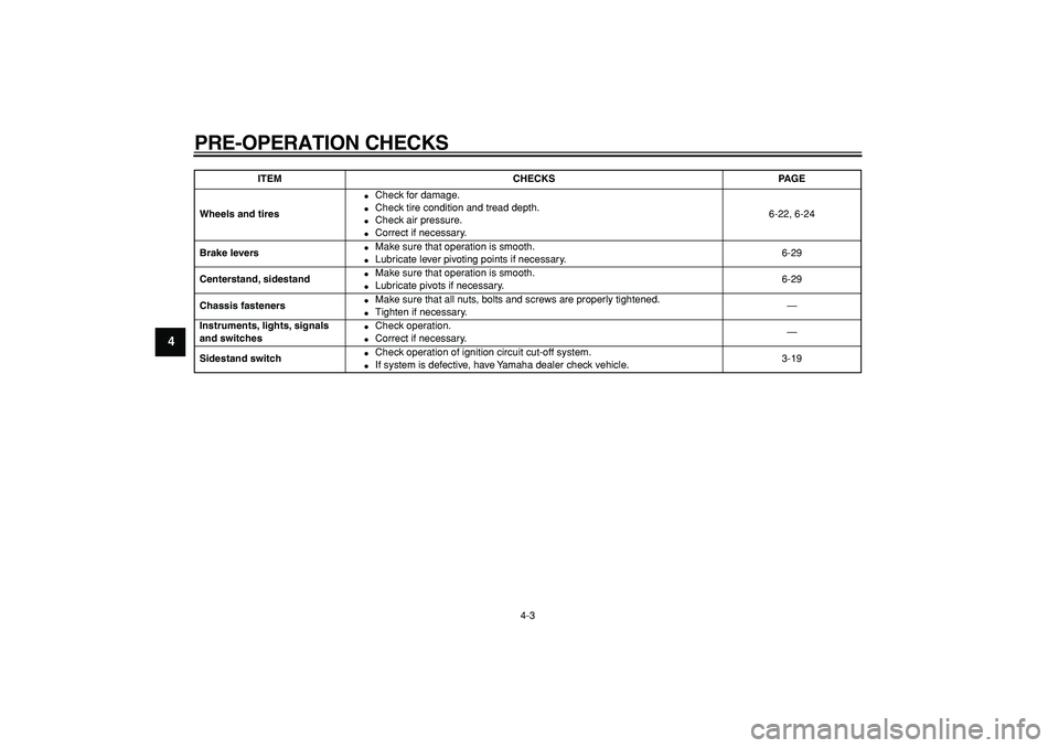
PRE-OPERATION CHECKS
4-3
1
2
3
4
5
6
7
8
9
Wheels and tires
�
Check for damage.
�
Check tire condition and tread depth.
�
Check air pressure.
�
Correct if necessary.6-22, 6-24
Brake levers
�
Make sure that operation is smooth.
�
Lubricate lever pivoting points if necessary.6-29
Centerstand, sidestand
�
Make sure that operation is smooth.
�
Lubricate pivots if necessary.6-29
Chassis fasteners
�
Make sure that all nuts, bolts and screws are properly tightened.
�
Tighten if necessary.—
Instruments, lights, signals
and switches
�
Check operation.
�
Correct if necessary.—
Sidestand switch
�
Check operation of ignition circuit cut-off system.
�
If system is defective, have Yamaha dealer check vehicle.3-19
ITEM CHECKS PAGE
Page 43 of 98
OPERATION AND IMPORTANT RIDING POINTS
5-3
2
3
4
56
7
8
9 Rear
WARNING
EWA10300
�
Avoid braking hard or suddenly
(especially when leaning over to
one side), otherwise the scooter
may skid or overturn.
�
Railroad crossings, streetcar
rails, iron plates on road con-
struction sites, and manhole
covers become extremely slip-
pery when wet. Therefore, slow
down when approaching such
areas and cross them with cau-
tion.
�
Keep in mind that braking on a
wet road is much more difficult.
�
Ride slowly down a hill, as brak-ing downhill can be very diffi-
cult.
EAU16820
Tips for reducing fuel
consumption
Fuel consumption depends largely on
your riding style. Consider the following
tips to reduce fuel consumption:
�
Avoid high engine speeds during
acceleration.
�
Avoid high engine speeds with no
load on the engine.
�
Turn the engine off instead of let-
ting it idle for an extended length of
time (e.g., in traffic jams, at traffic
lights or at railroad crossings).
Page 49 of 98
![YAMAHA MAJESTY 400 2008 Owners Manual
PERIODIC MAINTENANCE AND MINOR REPAIR
6-5
2
3
4
5
67
8
9
22
Engine oil
�
Change. (See pages 3-5 and
6-13.)
√
When the oil change indicator flashes [every 5000 km (3000 mi)]
�
Check](/manual-img/51/50635/w960_50635-48.png "YAMAHA MAJESTY 400 2008 Owners Manual
PERIODIC MAINTENANCE AND MINOR REPAIR
6-5
2
3
4
5
67
8
9
22
Engine oil
�
Change. (See pages 3-5 and
6-13.)
√
When the oil change indicator flashes [every 5000 km (3000 mi)]
�
Check")
PERIODIC MAINTENANCE AND MINOR REPAIR
6-5
2
3
4
5
67
8
9
22
Engine oil
�
Change. (See pages 3-5 and
6-13.)
√
When the oil change indicator flashes [every 5000 km (3000 mi)]
�
Check oil level and vehicle for
oil leakage.Every 5000 km (3000 mi)
√
23
Engine oil filter ele-
ment
�
Replace.
√√√
24
*
Cooling system
�
Check coolant level and vehi-
cle for coolant leakage.
√√√√√
�
Change. Every 3 years
25
Final transmission
oil
�
Check vehicle for oil leakage.
√√ √
�
Change.
√√√√√√
26
*
V-belt
�
Replace. When the V-belt replacement indicator flashes [every 20000 km (12000 mi)]
27
*
Front and rear brake
switches
�
Check operation.
√√√√√√
28
Moving parts and
cables
�
Lubricate.
√√√√√
29
*
Throttle grip hous-
ing and cable
�
Check operation and free play.
�
Adjust the throttle cable free
play if necessary.
�
Lubricate the throttle grip
housing and cable.
√√√√√
30
*
Lights, signals and
switches
�
Check operation.
�
Adjust headlight beam.
√√√√√√
NO. ITEM CHECK OR MAINTENANCE JOBODOMETER READING
ANNUAL
CHECK 1000 km
(600 mi)10000 km
(6000 mi)20000 km
(12000 mi)30000 km
(18000 mi)40000 km
(24000 mi)
Page 53 of 98
PERIODIC MAINTENANCE AND MINOR REPAIR
6-9
2
3
4
5
67
8
9
2. Install the screw access cover by
placing it in its original position.
3. Install the grab bar by installing the
collars and grab bar bolts.
4. Install the passenger seat.
5. Install cowlings A and B.
Cowling E
To remove the cowling
1. Pull up the left floorboard mats as
shown.2. Remove the cowling screws.
3. Pull the cowling down slightly, and
then pull it outward as shown.To install the cowling
1. Insert the projections on the cowl-
ing into the slots as shown, and
then install the screws.
2. Place the left floorboard mats in
the original position.
Tightening torque:
Grab bar bolt:
23 Nm (2.3 m·kgf, 16.6 ft·lbf)
1. Left floorboard mat
1. Screw
1
1
1. Cowling E
1. Projection
1
1
1