Page 36 of 104

INSTRUMENT AND CONTROL FUNCTIONS
3-22
3
EAU13442
Catalytic converters This vehicle is equipped with catalytic
converters in the exhaust system.
WARNING
EWA10860
The exhaust system is hot after op-
eration. Make sure that the exhaust
system has cooled down before do-ing any maintenance work.CAUTION:
ECA10700
The following precautions must be
observed to prevent a fire hazard or
other damages.�
Use only unleaded gasoline.
The use of leaded gasoline will
cause unrepairable damage to
the catalytic converter.
�
Never park the vehicle near pos-
sible fire hazards such as grass
or other materials that easily
burn.
�
Do not allow the engine to idletoo long.
EAU39492
Seats Passenger seat
To remove the passenger seat1. Insert the key into the passenger
seat lock, and then turn it counter-
clockwise.
2. Lift the front of the passenger seat
and pull it forward.To install the passenger seat
1. Insert the projections on the rear of
the passenger seat into the seat
holders as shown, and then push
the front of the seat down to lock it
in place.
2. Remove the key.
Rider seat
To remove the rider seat1. Remove the passenger seat.
2. Push the rider seat lock lever, lo-
cated under the back of the rider
seat, to the left as shown, and then
pull the seat off.
1. Passenger seat lock
2. Unlock.
1. Projection
2. Seat holder
U2D2E2E0.book Page 22 Thursday, October 11, 2007 9:15 AM
Page 40 of 104
INSTRUMENT AND CONTROL FUNCTIONS
3-26
3
�
Do not exceed the maximum
load of 208 kg (459 lb) for the ve-hicle.
EAU39480
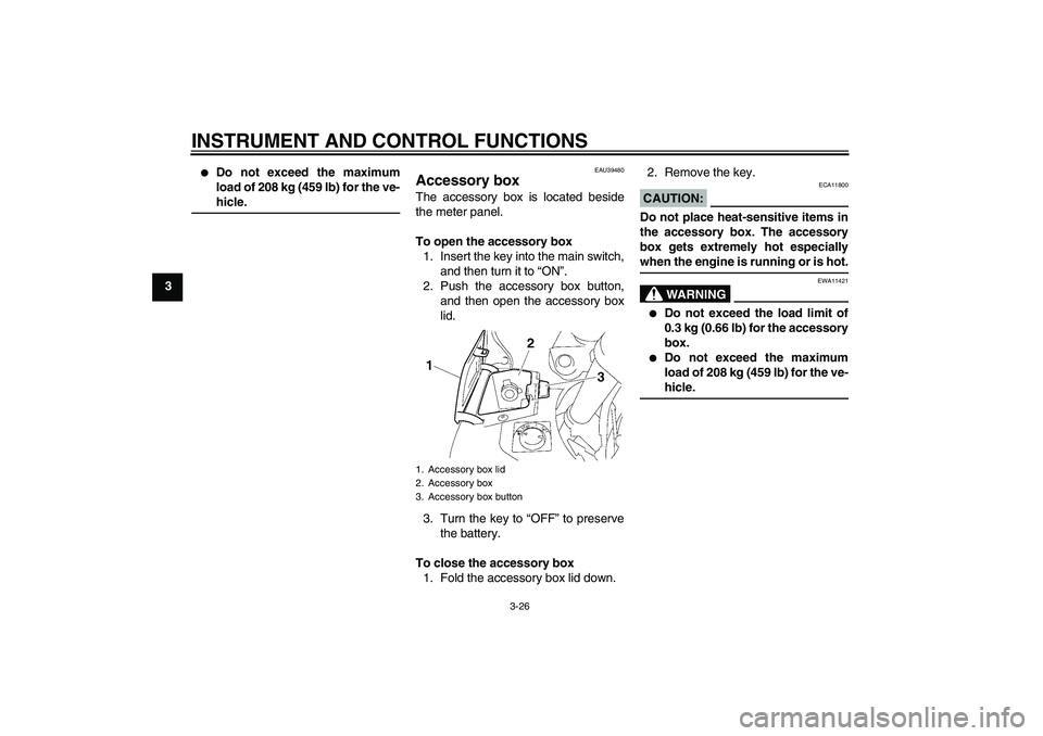
Accessory box The accessory box is located beside
the meter panel.
To open the accessory box
1. Insert the key into the main switch,
and then turn it to “ON”.
2. Push the accessory box button,
and then open the accessory box
lid.
3. Turn the key to “OFF” to preserve
the battery.
To close the accessory box
1. Fold the accessory box lid down.2. Remove the key.
CAUTION:
ECA11800
Do not place heat-sensitive items in
the accessory box. The accessory
box gets extremely hot especiallywhen the engine is running or is hot.
WARNING
EWA11421
�
Do not exceed the load limit of
0.3 kg (0.66 lb) for the accessory
box.
�
Do not exceed the maximum
load of 208 kg (459 lb) for the ve-hicle.
1. Accessory box lid
2. Accessory box
3. Accessory box button
U2D2E2E0.book Page 26 Thursday, October 11, 2007 9:15 AM
Page 46 of 104

INSTRUMENT AND CONTROL FUNCTIONS
3-32
3
EAU40501
Grip warmer adjusting knob This vehicle is equipped with grip
warmers, which can only be used when
the engine is running.
Use the grip warmer adjusting knob, lo-
cated near the accessory box, to adjust
the grip warmer temperature.
The grip warmer adjusting knob can be
set between the “LO” and “HI” posi-
tions. To raise the temperature, turn the
knob in direction (a). To lower the tem-
perature, turn the knob in direction (b).
Align the“” mark on the knob with
“OFF” to turn the grip warmers off.
NOTE:When the vehicle is stopped or travel-
ing at extremely low speeds (e.g., in
traffic jams), the grip warmer tempera-
ture is lower than when traveling athigher speeds.CAUTION:
ECA15520
�
Be sure to wear gloves when us-
ing the grip warmers.
�
If the ambient temperature is 20
°C (68 °F) or higher, do not set
the grip warmer adjusting knob
to the “HI” position.
�
If the handlebar grip or throttle
grip becomes worn or damaged,
stop using the grip warmers andreplace the grips.WARNING
EWA14510
Do not turn the grip warmer knobwhile the vehicle is moving.
EAU15301
Sidestand The sidestand is located on the left side
of the frame. Raise the sidestand or
lower it with your foot while holding the
vehicle upright.NOTE:The built-in sidestand switch is part of
the ignition circuit cut-off system, which
cuts the ignition in certain situations.
(See further down for an explanation ofthe ignition circuit cut-off system.)
WARNING
EWA10240
The vehicle must not be ridden with
the sidestand down, or if the side-
stand cannot be properly moved up
(or does not stay up), otherwise the
sidestand could contact the ground
and distract the operator, resulting
in a possible loss of control.
Yamaha’s ignition circuit cut-off
system has been designed to assist
the operator in fulfilling the respon-
sibility of raising the sidestand be-
fore starting off. Therefore, check
this system regularly as described
1.“LO” position
2.“OFF” position
3.“” mark
4. Grip warmer adjusting knob
5.“HI” positionU2D2E2E0.book Page 32 Thursday, October 11, 2007 9:15 AM
Page 47 of 104
INSTRUMENT AND CONTROL FUNCTIONS
3-33
3 below and have a Yamaha dealer re-
pair it if it does not function proper-
ly.
EAU40522
Ignition circuit cut-off system The ignition circuit cut-off system (com-
prising the sidestand switch and brake
light switches) has the following func-
tions.�
It prevents starting when the side-
stand is up, but neither brake is ap-
plied.
�
It prevents starting when either
brake is applied, but the sidestand
is still down.
�
It cuts the running engine when the
sidestand is moved down.
Periodically check the operation of the
ignition circuit cut-off system according
to the following procedure.WARNING
EWA10260
�
The vehicle must be placed on
the centerstand during this in-
spection.
�
If a malfunction is noted, have a
Yamaha dealer check the sys-tem before riding.
U2D2E2E0.book Page 33 Thursday, October 11, 2007 9:15 AM
Page 48 of 104

INSTRUMENT AND CONTROL FUNCTIONS
3-34
3
With the engine turned off:
1. Move the sidestand down.
2. Make sure that the engine stop switch is turned on.
3. Turn the key on.
4. Shift the transmission into the neutral position.
5. Keep the front or rear brake applied.
6. Push the start switch.
Does the engine start?
With the engine still running:
7. Move the sidestand up.
8. Keep the front or rear brake applied.
9. Shift the transmission into gear.
10. Move the sidestand down.
Does the engine stall?
After the engine has stalled:
11. Move the sidestand up.
12. Release the brake.
13. Push the start switch.
Does the engine start?
The system is OK. The vehicle can be ridden.The neutral, the brake switch or the YCC-S
system may be defective.
The vehicle should not be ridden until
checked by a Yamaha dealer.
The sidestand switch may be defective.
The vehicle should not be ridden until
checked by a Yamaha dealer.
A brake switch may be defective.
The vehicle should not be ridden until
checked by a Yamaha dealer.
NO YES YES NO YES NO
U2D2E2E0.book Page 34 Thursday, October 11, 2007 9:15 AM
Page 49 of 104

INSTRUMENT AND CONTROL FUNCTIONS
3-35
3
EAU39651
Auxiliary DC jack This vehicle is equipped with an auxilia-
ry DC jack in the accessory box.
A 12-V accessory connected to the
auxiliary jack can be used when the key
is in the “ON” position and should only
be used when the engine is running.CAUTION:
ECA15430
The accessory connected to the
auxiliary DC jack should not be used
with the engine turned off, and the
load must never exceed 30 W (2.5 A),
otherwise the battery may dis-charge.
To use the auxiliary DC jack
1. Open the accessory box lid. (See
page 3-26.)
2. Turn the key to “OFF”.
3. Remove the auxiliary DC jack cap.4. Insert the accessory plug into the
auxiliary DC jack.
5. Turn the key to “ON”, and then
start the engine. (See page 5-1.)
WARNING
EWA14360
To prevent electrical shock or short-
circuiting, make sure that the cap is
installed when the auxiliary DC jackis not being used.
1. Auxiliary DC jack cap
1. Auxiliary DC jack
U2D2E2E0.book Page 35 Thursday, October 11, 2007 9:15 AM
Page 51 of 104

PRE-OPERATION CHECKS
4-2
4
EAU15605
Pre-operation check list
ITEM CHECKS PAGE
FuelCheck fuel level in fuel tank.
Refuel if necessary.
Check fuel line for leakage.3-20
Engine oilCheck oil level in engine.
If necessary, add recommended oil to specified level.
Check vehicle for oil leakage.6-9
Final gear oilCheck vehicle for oil leakage. 6-12
CoolantCheck coolant level in reservoir.
If necessary, add recommended coolant to specified level.
Check cooling system for leakage.6-14
Front brakeCheck operation.
If soft or spongy, have Yamaha dealer bleed hydraulic system.
Check brake pads for wear.
Replace if necessary.
Check fluid level in reservoir.
If necessary, add recommended brake fluid to specified level.
Check hydraulic system for leakage.6-20, 6-21
Rear brakeCheck operation.
If soft or spongy, have Yamaha dealer bleed hydraulic system.
Check brake pads for wear.
Replace if necessary.
Check fluid level in reservoir.
If necessary, add recommended brake fluid to specified level.
Check hydraulic system for leakage.6-20, 6-21
YCC-S clutchCheck operation.
Check fluid level in reservoir.
If necessary, add recommended fluid to specified level.
Check hydraulic system for leakage.6-20, 6-21
U2D2E2E0.book Page 2 Thursday, October 11, 2007 9:15 AM
Page 53 of 104

OPERATION AND IMPORTANT RIDING POINTS
5-1
5
EAU15950
WARNING
EWA10270
�
Become thoroughly familiar
with all operating controls and
their functions before riding.
Consult a Yamaha dealer re-
garding any control or function
that you do not thoroughly un-
derstand.
�
Never start the engine or oper-
ate it in a closed area for any
length of time. Exhaust fumes
are poisonous, and inhaling
them can cause loss of con-
sciousness and death within a
short time. Always make sure
that there is adequate ventila-
tion.
�
Before starting out, make sure
that the sidestand is up. If the
sidestand is not raised com-
pletely, it could contact the
ground and distract the opera-
tor, resulting in a possible lossof control.
EAU45310
NOTE:This model is equipped with a lean an-
gle sensor to stop the engine in case of
a turnover. To start the engine after a
turnover, be sure to turn the main
switch to “OFF” and then to “ON”. Fail-
ing to do so will prevent the engine from
starting even though the engine willcrank when pushing the start switch.
EAU40332
Starting the engine In order for the ignition circuit cut-off
system to enable starting, one of the
following conditions must be met:�
The front or rear brake is applied
with the transmission in the neutral
position whether the sidestand is
up or down.
�
The front or rear brake is applied
with the transmission in gear and
the sidestand is up.WARNING
EWA14540
�
Before starting the engine,
check the function of the igni-
tion circuit cut-off system ac-
cording to the procedure
described on page 3-33.
�
Always apply the front or rear
brake while the main switch is in
the “ON” position and the trans-
mission is in gear, otherwise the
rear wheel will move freely.
�
Never ride with the sidestanddown.
1. Turn the key to “ON” and make
sure that the engine stop switch is
set to“”.
U2D2E2E0.book Page 1 Thursday, October 11, 2007 9:15 AM