Page 192 of 275
199 05 During your trip
Loading
Grocery bag holder1
Grocery bag holder under the floor of the trunk
The grocery bag holder holds shopping bags in place.
1. Open the hatch in floor of the trunk.
2. Secure the shopping bags with the strap.
1Available on certain markets only.
Ski hatch
There is a hatch in the right section of the rear seat backrest that can be opened for transportation.
Page 196 of 275

204 05 During your trip
Emergency towing
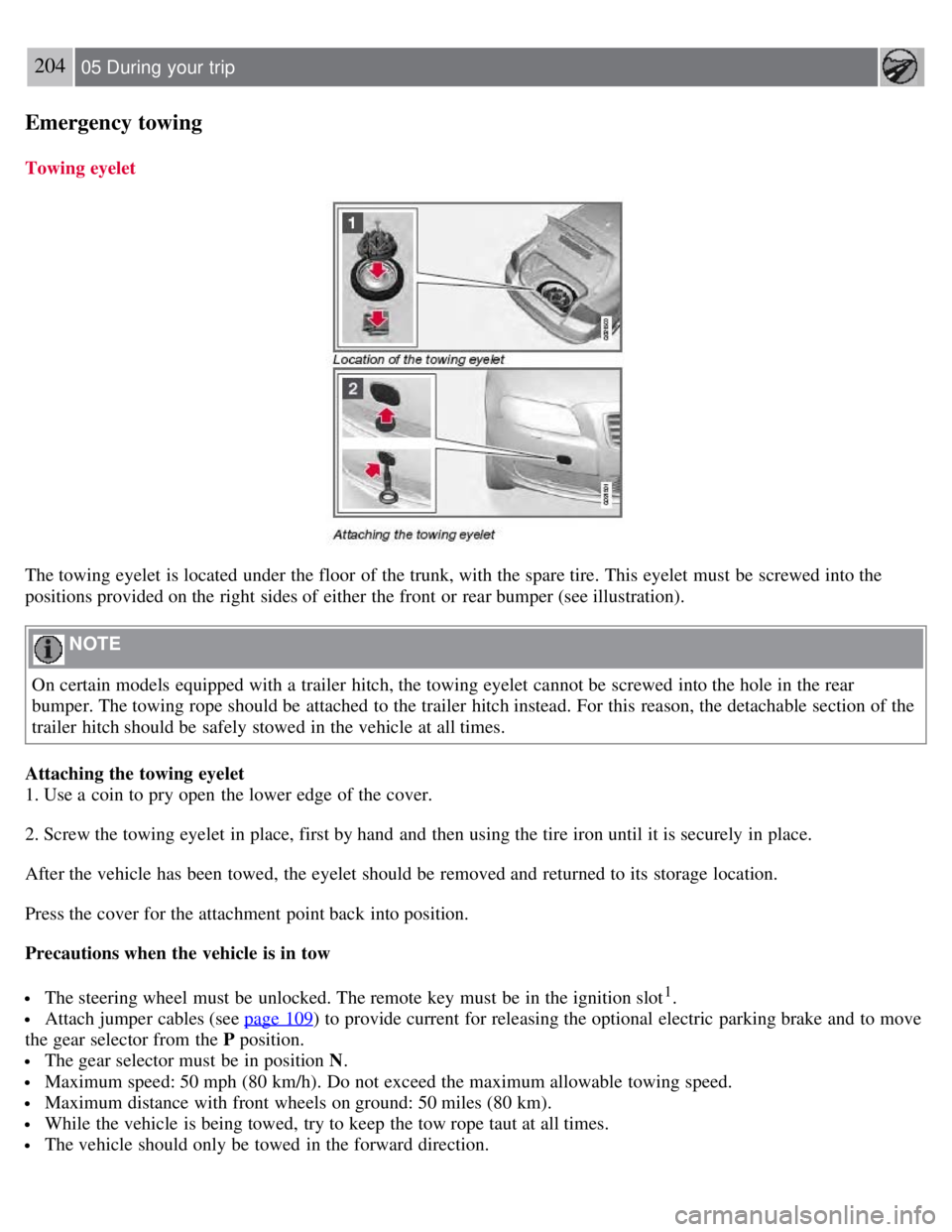
Towing eyelet
The towing eyelet is located under the floor of the trunk, with the spare tire. This eyelet must be screwed into the
positions provided on the right sides of either the front or rear bumper (see illustration).
NOTE
On certain models equipped with a trailer hitch, the towing eyelet cannot be screwed into the hole in the rear
bumper. The towing rope should be attached to the trailer hitch instead. For this reason, the detachable section of the
trailer hitch should be safely stowed in the vehicle at all times.
Attaching the towing eyelet
1. Use a coin to pry open the lower edge of the cover.
2. Screw the towing eyelet in place, first by hand and then using the tire iron until it is securely in place.
After the vehicle has been towed, the eyelet should be removed and returned to its storage location.
Press the cover for the attachment point back into position.
Precautions when the vehicle is in tow
The steering wheel must be unlocked. The remote key must be in the ignition slot1.
Attach jumper cables (see page 109) to provide current for releasing the optional electric parking brake and to move
the gear selector from the P position.
The gear selector must be in position N .
Maximum speed: 50 mph (80 km/h). Do not exceed the maximum allowable towing speed.
Maximum distance with front wheels on ground: 50 miles (80 km).
While the vehicle is being towed, try to keep the tow rope taut at all times.
The vehicle should only be towed in the forward direction.
Page 214 of 275
Turn signal
Rear fog light (driver's side only)
Backup light
License plate lighting
1. Remove the screws with a screwdriver.
2. Carefully detach the entire bulb housing and pull it out.
3. Replace the bulb.
4. Refit the entire bulb housing and screw it into place.
222 06 Maintenance and specifications
Replacing bulbs
Footwell lighting
1. Insert a screwdriver at the short end of the lens closest to the tunnel console (the center of the vehicle) and turn
gently so that the lens comes loose. (Applies to both lights).
2. Turn carefully until the lens comes loose.
3. Replace the bulb.
4. Press the lens back into place.
Trunk lighting
Page 215 of 275
NOTE
Before starting to replace a bulb, see page 216
.
The trunk lighting is located on opposite sides of the trunk.
1. Insert a screwdriver and gently turn so that the bulb housing comes loose.
2. Replace the bulb.
3. Check that the bulb illuminates and press it back into the bulb housing.
Vanity mirror lighting
Removing the mirror glass
1. Insert a screwdriver underneath the lower edge, in the center, turn and carefully pry up the lug on the edge.
2. Insert the screwdriver underneath the edge on the left and right sides (by the black rubber sections), and pry
carefully so that the glass comes loose in the lower edge.
3. Carefully detach and lift aside the entire mirror glass and cover.
4. Replace the bulb.
Reinstalling the mirror glass
1. Press the three lugs at top edge of the mirror glass back into position.
2. Press the three lower lugs back into position.
223 06 Maintenance and specifications
Page 222 of 275

Fuses
Replacing fuses
There are relay/fuse boxes located in the engine compartment, the passenger compartment, and the trunk.
If an electrical component fails to function, this may be due to a blown fuse. The easiest way to see if a fuse is blown
is to remove it.
To do so:
1. Pull the fuse straight out. If a fuse is difficult to remove, special fuse removal tools are located on the inside of the
fuse box covers.
2. From the side, examine the curved metal wire in the fuse to see if it is intact.
If the wire is broken, insert a new fuse of the same color and amperage (written on the fuse).
If fuses burn out repeatedly, have the electrical system inspected by a trained and qualified Volvo service technician.
WARNING
Never use metal objects or fuses with higher amperage than those stated on the following pages. Doing so could
seriously damage or overload the vehicle's electrical system.
Location of the fuse boxes
Under the glove compartment
Engine compartment
Trunk
231 06 Maintenance and specifications
Fuses
Engine compartment
Page 225 of 275
234 06 Maintenance and specifications
Fuses
Trunk
Page 246 of 275

Tire sealing system
Certain models are equipped with a tire sealing system that enables you to temporarily seal a hole in the tread surface
and reinflate a flat tire, or to adjust a tire's inflation pressure.
The system consists of an air compressor, a container for the sealing compound, wiring to connect the system to the
vehicle's electrical system via one of the 12-volt sockets, and a hose used to connect the system to the tire's inflation
valve.
The 12-volt sockets are located in the front tunnel console, on the rear side of the center console in the rear seat. See
page 185
.
Accessing the tire sealing system
The tire sealing system is stowed under the floor of the trunk. To access it:
1. Fold up the floor carpeting, starting at the rear and working forward.
2. Remove the retaining screws
3. Lift out the foam plastic block holding the jack and lug wrench.
4. Lift out the tire sealing system.
NOTE
The tire sealing system is only intended to seal holes on the tire's tread area, not the sidewall.
Tires with large holes or tears cannot be repaired with the tire sealing system.
WARNING
After using the tire sealing system, the vehicle should not be driven farther than approximately 120 miles (200
km).
Have the tire inspected by a qualified service technician as soon as possible to determine if it can be permanently
repaired or must be replaced.
The vehicle should not be driven faster than 50 mph (80 km/h) while using a tire that has been temporarily
repaired with the tire sealing system.
After using the tire sealing system, drive carefully and avoid abrupt steering maneuvers and sudden stops.
257 06 Maintenance and specifications
Wheels and tires
Tire sealing system -overview
Page 265 of 275
Geartronic110-111
general description110- 111
oil275
shiftlock override111
Axle weight 247
B
Battery
changing 227-228
maintenance227
remote control, replacing59
specifications276
warning symbols226
Black box 6, 208
Blind Spot Information System(BLIS)179-181
Booster cushion, integrated45-47
Booster cushions41
Brake lights91
emergency brake lights91
Brake support 166
Brake system
checking fluid level 215
emergency brake assistance114
fluid275
general information113
warning light77
Bulbs
footwell lighting 222
headlights216- 218
introduction216
license plate lights221
side marker lights219
specifications223
taillight219- 221
trunk lighting222
C
Capacity weight 247
Catalytic converter196
CD player/changer138-139
Central locking system, introduction52
Chains250
Check engine light75
Child restraint systems34-35
booster cushions41
convertible seats38- 40