2008 VOLKSWAGEN SCIROCCO LED
[x] Cancel search: LEDPage 18 of 138
Downloaded from www.Manualslib.com manuals search engine Legend for Fig . 13 See
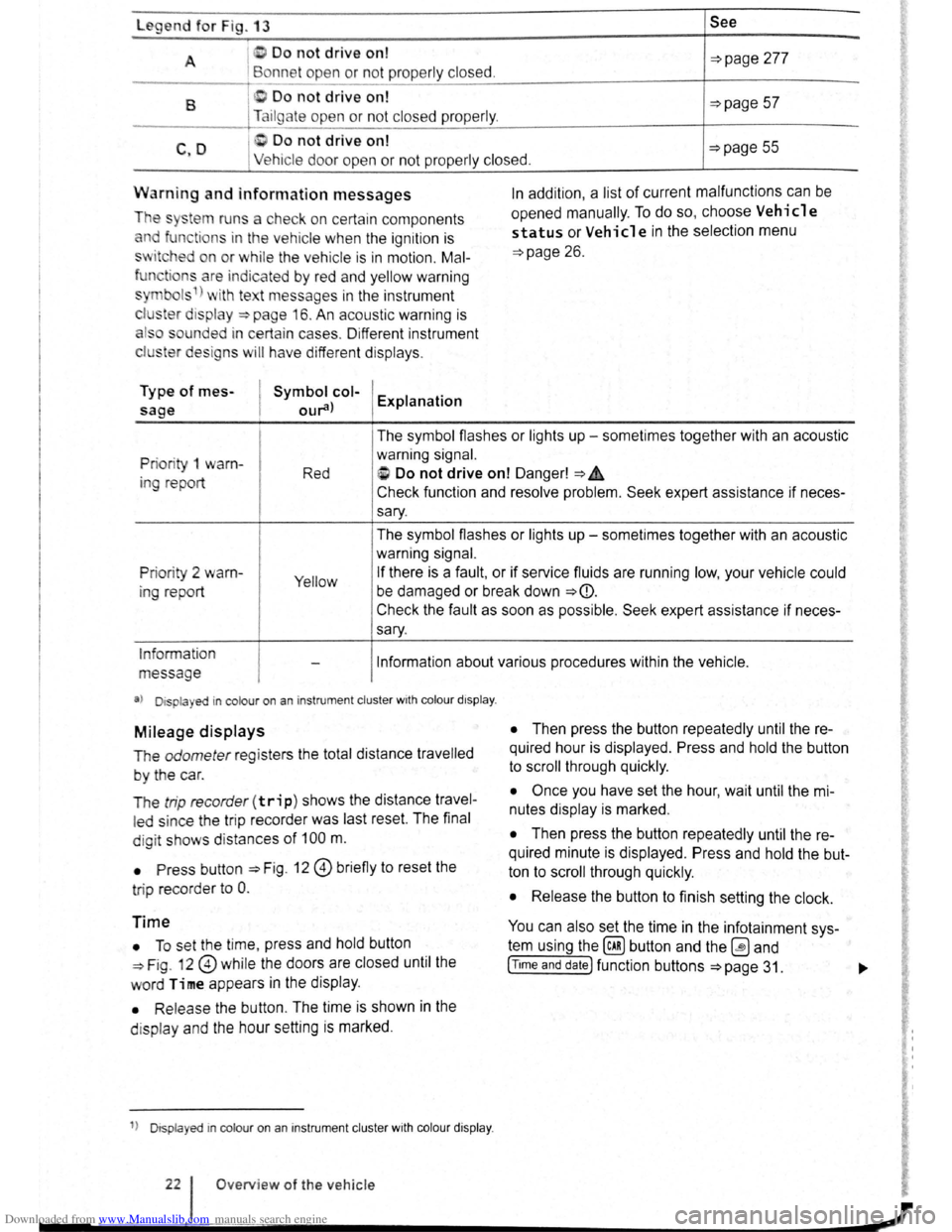
A I D o not drive on!
Bonne t ope n or not prope rly closed. ~page 277
B 0 Do not drive on! ~page 57 Tailgate open or no t closed prope rly .
C Do not drive on! C ,D Ve hicle door ope n or n ot pr ope rly clos ed. ~page 55
Warn ing and information messages
The sy~tem runs a che ck o n ce rtain components
and function s in the vehicle whe n the ignition is
sw itched on or w hil e the ve hi cle is in motion . Mal
fun tions ar e indic ated by r ed and yellow warning
s ymbol s 1
) wi th te t message s in the instrument
c l
1ster d is pla y ~page 16. An acoustic warning is
a ls o so unded i n certa in ca se s. Di fferent instrument
clu ster design s
will h av e diffe rent dis plays .
Type of mes
sage
Symbol col
our
opened manually.
To do so, choose Vehicle
status or Vehicle in the selection menu
~page 26.
Priori ty 1 warn
in g re port The
symbol flashes or lights up -sometimes together with an acoustic
warning signal.
Red i> Do not drive on! Danger! ~A
Check function and resolve problem. Seek expert assistance if neces
sary.
The symbol flashes or lights up -sometimes together with an acoustic
warning signal.
Prio rity 2 warn
ing report Yellow If there is a fault, or if service fluids are running low, your vehicle could
be damaged or break down
~CD.
Check the fault as soon as possible . Seek expert assistance if neces
sary.
Information
message Information about various procedures within the vehicle .
a) Displa yed in colour on an i nstrumen t cluster wit h co lour d isplay .
Mileage displays
The odometer re gi sters the total distance travelled
by the car.
T he
trip recorde r(trip) shows the distance travel
led since the trip reco rder was last reset. The final
d ig it show s dis tan ces
of 100 m.
• Press button ::::>Fig . 12 0 briefly to reset the
tri p record
er to 0 .
Time
• To se t th e t ime , press and hold button
~Fig. 12 0 while the doors are closed until the
word Time appears in the display .
• Releas e the button . The time is shown in the
d is p l
ay and the hour setting is marked .
1
) D isp layed in col our on an instrum ent clu ste r with col our di sp la y.
O ve rview of the ve hicle
• Then press the button repeatedly until the re
quired hour is displayed . Press and hold the button
to scroll through quickly.
• Once you have set the hour, wait until the mi
nutes display is marked .
• Then press the button repeatedly until the re
quired minute is displayed. Press and hold the but
ton to scroll through quickly.
• Release the button to finish setting the clock.
You can also set the time in the infotainment sys
tem using the@) button and the ~ and
[T tme and date] function buttons ~page 31. ..,.
Page 25 of 138
Downloaded from www.Manualslib.com manuals search engine Driving data
r-T'n ~irst rea~ and observe the introductory
L......kJJ mformat1on and safety warnings ~on
page 26.
• Since start
• Since refuel
• long-term
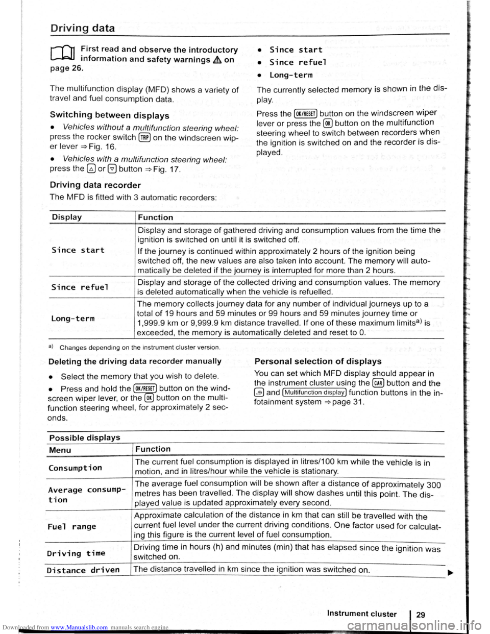
The multifunction display (MFD) shows a variety of
travel and fuel consumption data.
The currently selected memory is shown in the dis
play.
Switching between displays Press the [OK/RESET] button on the windscreen wiper
lever or press the @ button on the multifunction
steering wheel to switch between recorders
when
the ignition is switched on and the recorder is dis
played.
• Vehicles without a multifunction steering wheel:
press the rocker switch
(!ill on the windscreen wip
er lever ~Fig. 16.
• Vehicles with a multifunction steering wheel:
press
the~ or@ button ~Fig. 17 .
Driving data recorder
The MFD is fitted with 3 automatic recorders:
Display
Since start
Since refuel
Long-term
Function
Display and storage of gathered driving and consumption values from the time the
ignition is switched on until it is switched off.
If the journey is continued within approximately 2 hours of the ignition being
switched
off, the new values are also taken into account. The memory will auto
matically be deleted
if the journey is interrupted for more than 2 hours.
Display and storage
of the collected driving and consumption values. The memory
is deleted automatically when the vehicle is refuelled .
The memory collects journey data for any number of individual journeys up to a
total
of 19 hours and 59 minutes or 99 hours and 59 minutes journey time or
1,999.9 km or 9,999 .9 km distance travelled. If one of these maximum limitsa) is
exceeded, the
memory is automatically deleted and reset to 0.
a) Changes depending on the instrument cluster version.
Deleting the driving data recorder manually Personal selection of displays
• Select the memory that you wish to delete. You can set which MFD display should appear in
the instrument cluster using the
@ill button and the
~and [Multifunction display) function buttons in the in
fotainment system
~page 31.
• Press and hold the OK/RESET button on the wind
screen
wiper lev er, or the OK button on the multi
function steering wheel, for approximately 2 sec
onds.
Possible displays
Menu
Consumption
Average consump
tion
Fuel range
Driving time
Function
The current fuel consumption is displayed in litres/1 00 km while the vehicle is in
motion, and in litres/hour while the vehicle is stationary.
The average fuel consumption will be shown after a distance of approximately 300
metres has been travelled . The display will show dashes until this point. The dis
played value is updated approximately every second.
Approximate calculation
of the distance in km that can still be travelled with the
current fuel level under the current driving conditions . One factor used for calculat
ing this figure is the current level
of fuel consumption .
Driving
time in hours (h) and minutes (min) that has elapsed since the ignition was
switched on.
Distance driven The distance travelled in km since the ignition was switched on. ..... ~~~--------~--------------------------~----------------------------~
Instrument cluster 29
Page 26 of 138
Downloaded from www.Manualslib.com manuals search engine Possible displays
Menu Function
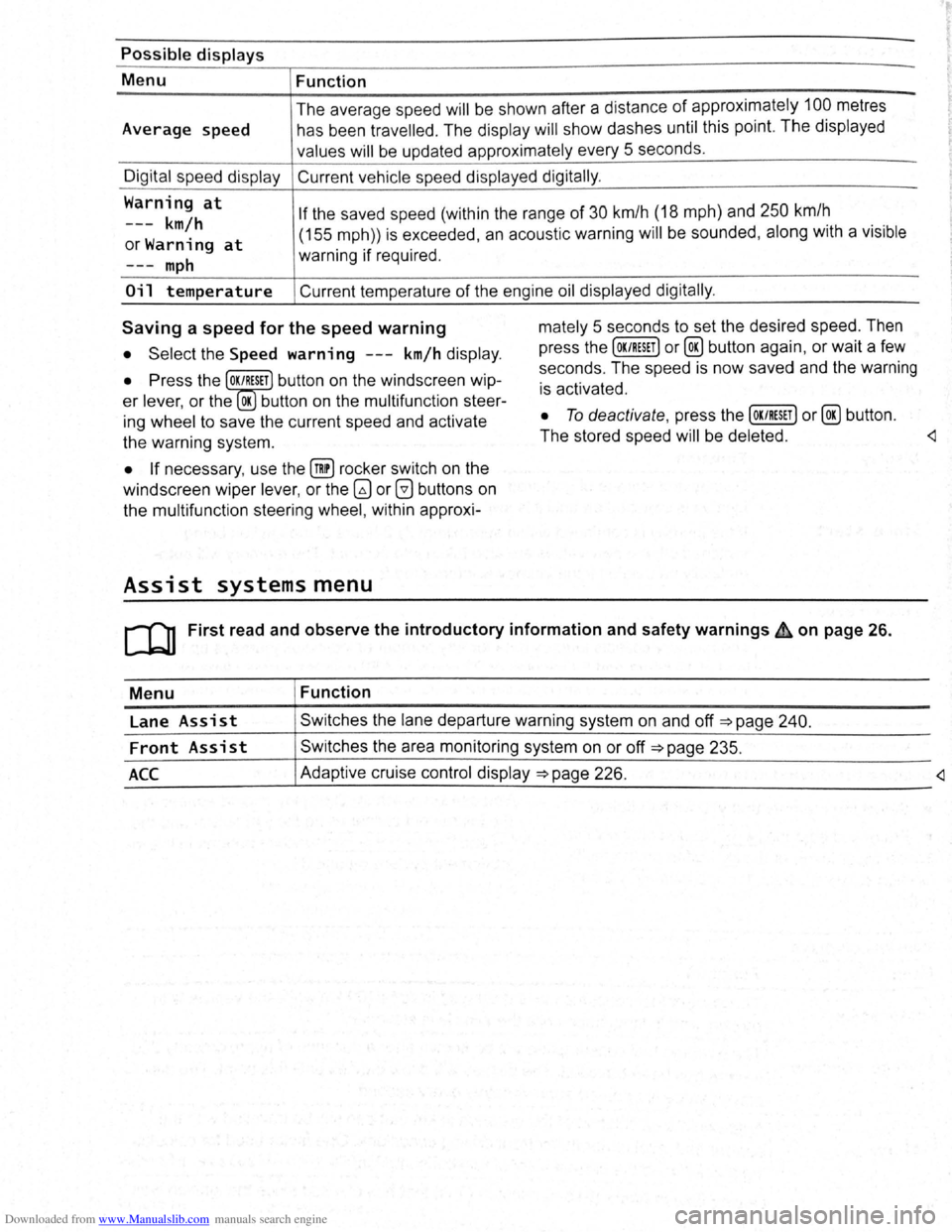
Average speed The
average sp ee d
will be shown after a distan ce of appro ximately 100 metres
h as be en trav e
lled . The display will show dashes until this point. The displayed
valu es
will be updated approximately every 5 se conds .
Digit al sp ee d display Current vehicle speed displayed digitally .
Warning
at
---km/h
orWarning at
If the saved speed (within the range of 30 km/h (18 mph) and 250 km/h
m
ph
(155 mph)) is exceeded , an acoustic warning will be sounded , along with a vis ible
warning if required .
Oil temperature Current temperature of the engine oil displayed digitally .
Saving a speed for the speed warning
• Select the Speed warning ---km/h display .
• Press the OK/RESET button on the windscreen wip
er lever, or the OK button on the multifunction steer
ing wheel to save the current speed and activate
the warning system.
• If necessary , use the @!) rocker switch on the
windscreen wiper lever, or the
G) or 0 buttons on
the multifunction steering wheel, within approxi-
Assist systems menu
mately 5 seconds to set the desired speed. Then
press the
[OK/RESET] or@ button again, or wait a few
seconds . The speed is now saved and the warning
is activated .
• To deactivate , press the [OK/RESET] or@ button .
The stored speed
will be deleted .
Menu Function
Lane
Assist Swi tches the lane departure warning system on and off =>page 240.
Front Assist Switches the area monitoring system on or off =>page 235.
_A_c_c ____________ ~A_d_a~p_tiv_e __ cr_u_is_e_c_o_n_tr_o_ld_i~sp_l~ay~=>~p_a~g~e~2~2~6~·----------------------------
Page 41 of 138
Downloaded from www.Manualslib.com manuals search engine -
SAFELOCK mechanism
ro ~irst rea? and observe the introductory
mformat1on and safety warnings on
~.wl~ 11 { nt k ( I I tl l { ..
I' 1 t 1'klnt~l l .
page 46.
Function Action
L
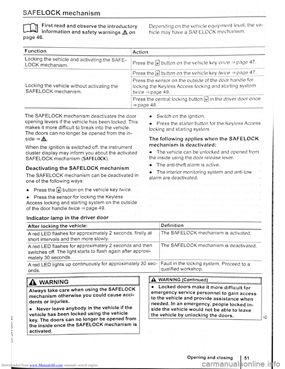
ocking the vehicle and activating the SAFE-
LOCK mechanism. P ress tl1 Q) Jlt n nth
Locking the vehicle without activat in g the
SAFELOCK mechanis m .
The SAFELOCK mechanis m deactivates the do r
opening levers if the v e hic le has been lock ed . Th is
makes it more d ifficult to break in to the vehicle .
The doors can no longer be opened from th e in
side~&..
When the ignition is switched off, th e instrum ent
cluster display may inform you about t he activated
SAFELOCK mechani sm (SAFELOCK).
Deactivating the SAFELOCK mechanism
The SAFELOCK mechanis m can be deactivated in
one of the following ways:
• Press the @ button on the veh icle key twic e .
• Press the sensor fo r lock ing the Keyless
Access locking and s tarting system on the outs ide
of the door handle twice ~page 49.
Indicator lamp in the driver door
The following applies when th SAFELOCK
mechanism is deactivated:
• The ehi le n e unl
t
he in side u in the d
• The anti-theft
nit rin
ted .
nti-t v
After locking the vehicle: Definition
A red LED flash es for approximately 2 seconds , firstly at The SAFELOC
short intervals and then more slowly .
A red
LED flashes for approximate ly 2 seconds and then The SAFELOCK me hanism is de
switches off. The light starts to flash again after approx i-
mately 30 seconds.
A red
LED lights up cont inuous ly for approx imate ly 30 sec-~ Fault in the lock ing s
onds. , qual ified v or shop.
A WARNING
Always take care when using the SAFELOCK
mechanism otherwise you could cause acci
dents or injuries.
• Never leave anybody in the vehicle if the
vehicle has been locked using the vehicle
key. The doors can no longer be opened from
the inside once the SAFELOCK mechanism is
activated.
A WARNING {Continued}
• Locked doors make it more difficult for
emergency service personnel to gain access
to the vehicle and provide assistance when
needed. In an emergency people locked in
side the vehicle would not be able to leave
the vehicle by unlocking the doors.
Page 52 of 138
Downloaded from www.Manualslib.com manuals search engine ~emoving and fitting head restraints
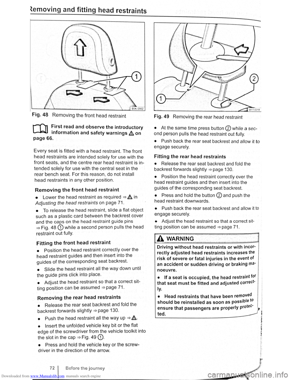
Fig. 48 Removing the front head restraint
r-f'n First read and observe the introductory
L-lcJJ information and safety warnings & on
page 66.
Every seat is fitted with a head restraint. The front
head restraints are intended solely for use with the
front seats, and the centre rear head restra int is in
tended solely for use with the central seat in the
rear bench seat. For this reason , do not install
head restraints in any other position.
Removing the front head restraint
• Lower the head restraint as required ===> & in
Adjusting the head restraints on page 71.
• To release the head restraint , slide a flat object
such as a plas tic card between the backrest cover
and the caps on the head restraint guide pins
===>Fig. 48 G) while a second person pulls the head
restraint
out fully .
Fitting the front head restraint
• Position the head restraint correctly over the
head restraint guides and then insert into the
guides of the corresponding seat backrest.
• Slide the head restraint all the way down until
the guide pins click into place .
• Adjust the head restraint so that a correct sit
ting position can be assumed
===>page 71.
Removing the rear head restraints
• Release the rear seat backrest and fold the
backrest forwards slightly
===>page 130.
• Push
the head restraint all the way up ===> &.
• Insert the unfolded vehicle key bit or the flat
edge
of the screwdriver from the vehicle tool kit into
the slot in the cap
===>Fig. 49 G).
• Press and hold the vehicle key or the screw
driver in the direction
of the arrow .
Before the journey
Fig. 49 Removing the rear head restraint
• At the same time press button @ while a sec
ond person
pulls the head restraint out fully .
• Push back the rear seat backrest and allow it to
engage securely .
Fitting the rear head restraints
• Release the rear seat backrest and fold the
backrest forwards slightly
===>page 130.
• Position
the head restraint correctly over the
head restraint guides and then insert into the
guides
of the corresponding seat backrest.
• Press and hold the button @and push the
head restraint downwards .
• Push back the rear seat backrest and allow it to
engage securely.
• Adjust the head restraint so that a correct sit
ting position can be assumed ===>page 71.
A WARNING .
Driving without head restraints or with incor·
rectly adjusted head restraints increases the
risk of severe or fatal injuries in the event of
an
accident or sudden driving or braking ma·
noeuvre.
• If a seat is occupied, the head restraint tor
that seat must be fitted and adjusted correct·
ly.
•
Head restraints that have been removed
should be reinstalled as soon as possible to
tee· ensure that passengers are properly pro ~
~ ted.
) )
.
~ . ,
Page 55 of 138
Downloaded from www.Manualslib.com manuals search engine Seat functions
[ Introduction
1 hi · chnptor contnins inforrnntion o n th e follo wing
sub wrts :
'" t dt ll 'nting . . . . . . . . . . . . . . . . . . . . . . . . . . . 75
8dl.k nm~S<. g fun ction . . . . . . . . . . . . . . . . . . . 76
F lldm .. th front Pt ~seng r s n t bac kres t
ft.)rWflrd.. . . . . . . . . . . . . . . . . . . . . . . . . . . . . . . . 77
Additiona l inforn1ation and warnings:
• Adjus ting the s t1t po sitio n ;;. page 66
• S at b Its -:-pag e 79
• Airbrtg sys te m => pag e 88
• Child s ts (accessories ) ::::>page 97
• Ex t rior mirr ors =-> pflge 1 22
• Arr condi tio ning ->page 256
Seat heating
c.:.:..J L.:..J L..:..l
BAJ -0013
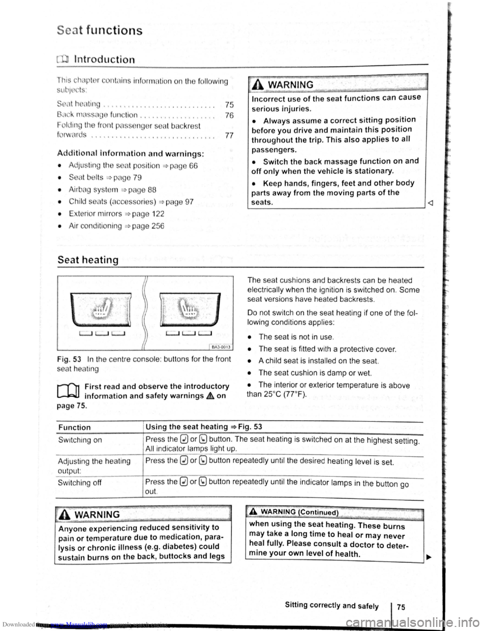
Fig . 53 In the ce ntre conso le : butt ons for the front
sea t
hea trng
i""""fl1 First read and observe the introductory
L-...lr::JJ information and safety warnings £ on
page
75.
Incorrect use of the seat functions can cause
serious Injuries.
• Always assume a correct sitting position
before you drive and maintain this position
throughout the trip. This also applies to all
passengers.
• Switch the back massage function on and
off only when the vehicle is stationary.
• Keep hands , fingers, feet and other body
parts away from the moving parts of the
seats.
elec trical ly when the ignition is switched on.
Some
seat ve rsions have heated backrests .
Do not switc h on the seat heating if one of the fol
lowing conditions applies:
• The seat is not in u se.
• The seat is fitted with a protect ive cover.
• A chi ld seat is installed on the seat.
• The seat cushion is damp or wet.
• The interior or exterior tempera ture is above
than 25oc (77 °F) .
Function Using
the seat heating ::::>Fig. 53
Swrtching on
Adjus ting
the heating
output:
Swi tchi ng off
Press the 0 or (9 button. The seat heating is switched on at the highest setting.
All indicato r l amps light up.
Pre ss the
0 or (9 button repeatedly until the desired heating level is set.
Press the
0 or (9 button repeatedly until the ind ica tor lamps in the button go
out.
~A WARNING (Continued) " ._..~~1 ~...... -~.~. ~-~ ~----J
Anyone experiencing reduced sensitivity to
pain or temperature due to medication, para
lysis or chronic illness (e.g. diabetes) could
sustain burns on the back, buttocks and legs when
using the
seat heating. These burns
may take a long time to heal or may never
heal fully. Please consult a doctor to deter
mine your own level of health.
~--------------~--------~~
Sitting correctly and safely 75
Page 57 of 138
Downloaded from www.Manualslib.com manuals search engine Lights and vision
Lights
Introduction
Th1s ·hapt r c nt 1n inf rm lion on th e f llowing
utject :
lnd1 ator lamps . . <>-~ • .. .. .. .. .. • .. .. ~ • .. • .. • • .. •
Turn s1gnal and main beam lever ..•.......
Svvitching lights on and off .............. .
Lights
and v1sion -functions ............ .
~1ain beam ass1st . . . . . . . . . . . . . . . . ... .
Ma king or sv itching over headlights for
dnving abroad (travel mode) . . . . ........ .
Commg Home and Leaving Home functions
(onentation
lighting) . . . . . . . ............ .
Headl i
ght range control, instrument and
s~ itch lighting . . . . . . . . . . . . . . . ....
Interior and reading hght s ...............•.
105
106
107
108
110
111
111
112
113
Observe any country-spec•fic regu lations when us
ing veh1c le lighting.
The driver 1s responsib le for the correct headlight
pos1t1on and the correct headlight settm g.
Addit ional information and warnings:
• Exterior views ~page 6
• lnfotamment system ~page 31
• Changing bulbs ~page 362
Indicator lamps
A WARNING
Accidents and serious injuries can occur if
roads are not sufficiently illuminated and oth
er r oad users have d ifficulty seeing the vehi
cle, or cannot see it at all.
• Always switch the dipped beam head
lights on if it is dark, raining or visibility is
poor.
A WARNING
Setting headlights too high, and the incorrect
use of the main beam, could d istract and daz
zle other road users. This can lead to acci
dents and serious injuries.
• Always ensure that the headlights are ad
justed correctly.
• Never use the main beam or the headlight
flasher if other road users could be dazzled.
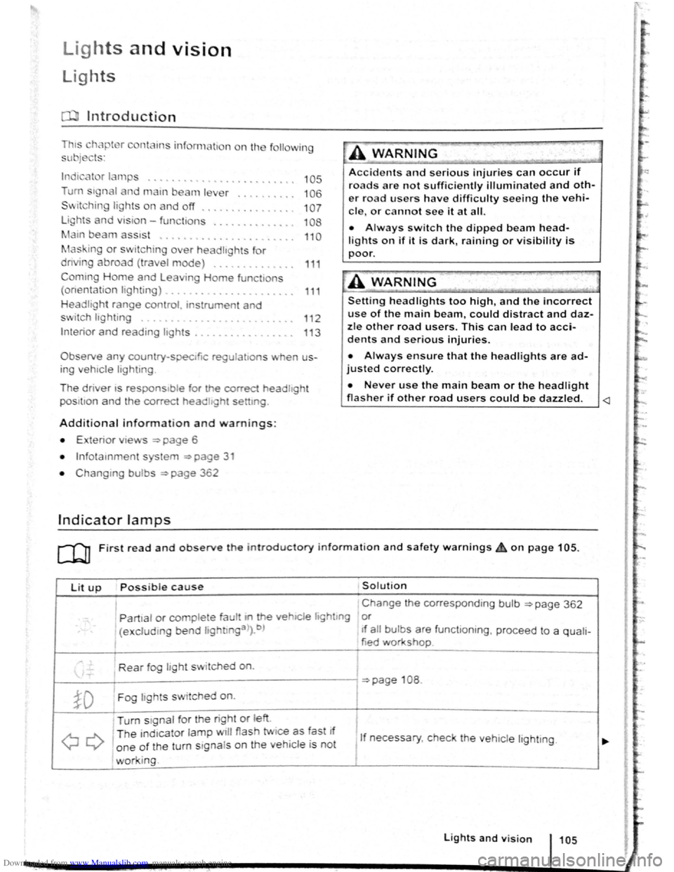
Lit up Possi ble cause Solution
I Change the corresponding bulb ~page 362
' Partial or complete fau tt m he vehiCle hghtmg or
(excluding bend lightlnga>).b ) If a ll bulbs are functioning , proceed to a quali-
tied workshop
Rear fog light switched on.
~page 108 .
~D Fog lights sw itched on. I
Turn stgnal for the right or left i
I
QQ
T he ind1cator lamp will flash twice as fast If
1 If necessary, c heck the vehicle lighting. o ne of the turn signals on the vehicl e is not
working. I
Lights and v is ion 105
Page 58 of 138
Downloaded from www.Manualslib.com manuals search engine Lit up Possible cause Solution
Tr ailer turn signal. -......
Q\~ The indica tor lamp goe s out if a tra iler turn Check the trailer l ighting as required.
signal
or all trailer lig ht s st op working .
Main beam is swi tc h e d on or the headlight
----D =>pa ge 106 .
flasher is being opera ted .
-
0 Main beam ass ist swi tc hed on. =>page 110 .
-1
) A separate display appears in the instrumen t cluster if there is a bend lighting fault.
>) Displayed in colour on an instru ment cluster with colour display .
Several warning and indicato r lamps will light up
briefly as a
functiona l check when the ign iti on i s
switched
on. T he y will swi tc h off after a few sec
onds.
--·--~-
Failure to observe illuminated warning lamps
and text messages can lead to your vehicle
breaking down in traffic, and can cause acci
dent and serious injury.
• Never ignore any illuminated warning
lamps or text messages.
• Stop the vehicle as soon as possible and
when safe to do so.
Turn signal and main beam lever
®
B5K ·0415
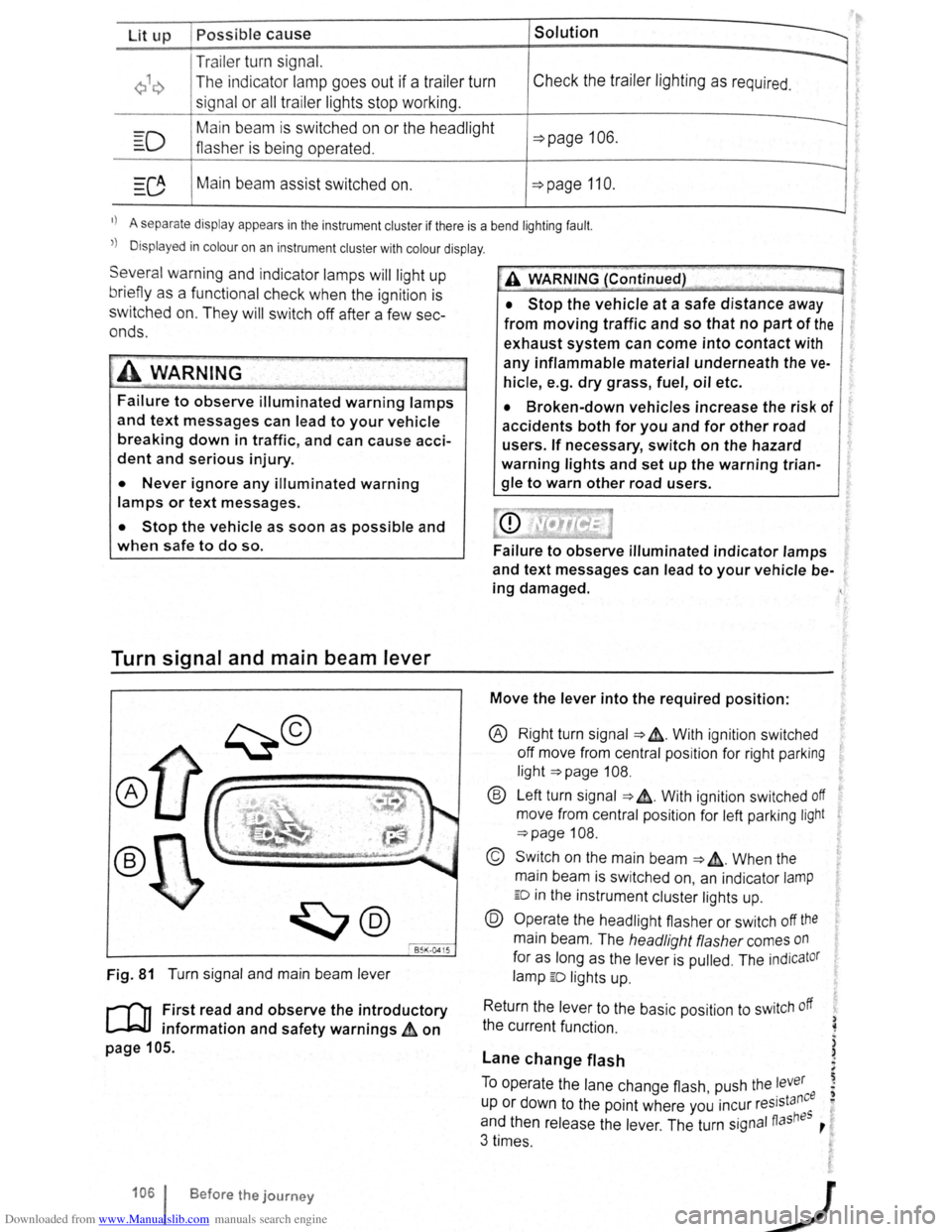
Fig. 81 T urn signa l and main beam lever
r-('n F irst read and observe the introductory
1.-J=JJ information and safety warnings~ on
page 105 .
1061 Before the journey
--
~>A WARNING (Continued) -
• Stop the vehicle at a safe distance away
from moving traffic and so that no part of the
exhaust system can come into contact with
any inflammable material underneath the ve
hicle, e .g . dry grass, fuel, oil etc.
• Broken-down vehicles increase the risk of
accidents both for you and for other road
users. If necessary, switch on the hazard
warning lights and set up the warning trian
gle to warn other road users.
Failure to observe illuminated indicator lamps
and text messages can lead to your vehicle be
ing damaged.
Move the lever into the required position:
® Right turn signa l ~ &. W it h ignit ion swi tched
off m ove from centr al posit io n for right parking
li g ht
~page 108.
® Left turn sig na l ~ ~. W ith ignition switched off
move from centra l posi tion for left parking light
~page 108 .
© Switch on the main beam ~ &. Whe n the
main beam is switc hed on, an indicator
lamp
ED in the instr ument cluster lights up.
@ Operate the headlight flasher or switch off the
main beam. The h eadligh t flasher comes on
for as long as the leve r is pulled . The indicator
lamp ED lights u p .
R etu
rn the le ver to the basic position to switch off
the c urrent fu nc tio n.
Lane change flash
) ~
)
)
To o pe rate the la ne c hange flash push the lever ' . nee I) u p or d own to the poin t where you incur reslsta eo
and th en release the le ver. The turn signal fiashBS ,
3 times .