Page 518 of 580
518 5-2. Steps to take in an emergency
To change “POWER” switch modes: Within 5 seconds of the
buzzer sounding, release the brake pedal and press the
“POWER” switch. Modes can be changed each time the
switch is pressed. ( P. 175)
To start the hybrid system: Press the “POWER” switch within
5 seconds after the buzzer sounds, keeping the brake pedal
depressed.
In the event that the hybrid system still cannot be operated, contact
your Toyota dealer.
■ Stopping the hybrid system
Shift the shift lever to P and press the “POWER” switch as you normally do
when stopping the hybrid system.
■ Replacing the key battery
As the above procedure is the temporary measure, it is recommended that
the electronic key battery be replaced immediately when the battery
depletes. ( P. 456)
STEP3
Page 519 of 580
5
When trouble arises
519
5-2. Steps to take in an emergency
If the vehicle 12-volt batter y is discharged
The following procedures may be used to start the hybrid system if
the vehicle's 12-volt battery is discharged.
You can call your Toyota dealer or qualified repair shop.
If you have a set of jumper (or boo ster) cables and a second vehi-
cle with a 12-volt battery, you can jump start your Toyota following
the steps below.
Connecting the jumper cables
If required, remove all vent plugs from the booster battery. Lay a
cloth over the open vents on t he booster battery. (This helps
reduce the explosion hazard, personal injuries and burns.)
Positive (+) battery terminal on your vehicle
Positive (+) battery terminal on the second vehicle
Negative (-) battery terminal on the second vehicle
Connect the jumper cable to ground on your vehicle as shown in
the illustration.
STEP1
Page 520 of 580

520 5-2. Steps to take in an emergency
■Avoiding a discharged 12-volt battery
●Turn off the headlights and the audio system while the hybrid system is
off.
● Turn off any unnecessary electrical components when the vehicle is run-
ning at a low speed for an extended period, such as in heavy traffic, etc.
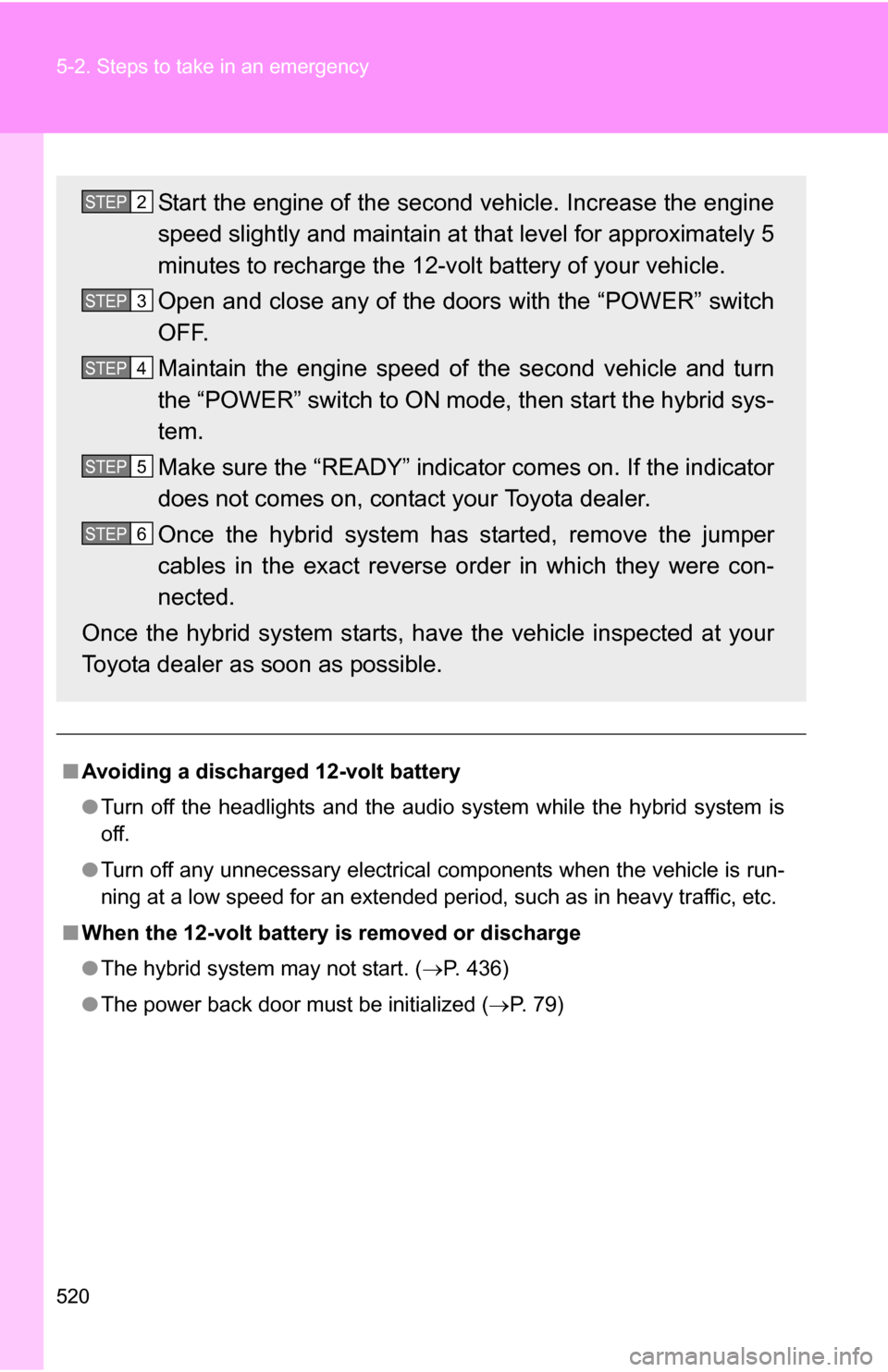
■ When the 12-volt battery is removed or discharge
●The hybrid system may not start. ( P. 436)
● The power back door must be initialized ( P. 7 9 )
Start the engine of the second vehicle. Increase the engine
speed slightly and maintain at that level for approximately 5
minutes to recharge the 12-v olt battery of your vehicle.
Open and close any of the doors with the “POWER” switch
OFF.
Maintain the engine speed of the second vehicle and turn
the “POWER” switch to ON mode, then start the hybrid sys-
tem.
Make sure the “READY” indicator comes on. If the indicator
does not comes on, contact your Toyota dealer.
Once the hybrid system has started, remove the jumper
cables in the exact reverse order in which they were con-
nected.
Once the hybrid system starts, ha ve the vehicle inspected at your
Toyota dealer as soon as possible.STEP2
STEP3
STEP4
STEP5
STEP6
Page 521 of 580

5
When trouble arises
521
5-2. Steps to take in an emergency
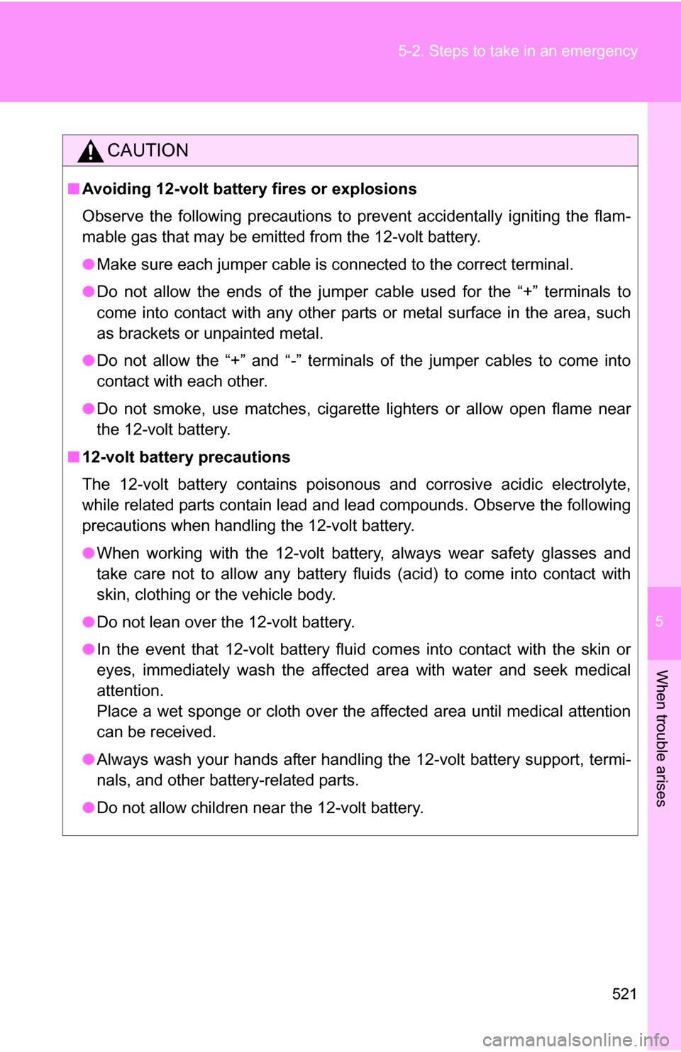
CAUTION
■
Avoiding 12-volt battery fires or explosions
Observe the following precautions to prevent accidentally igniting the flam-
mable gas that may be emitted from the 12-volt battery.
●Make sure each jumper cable is connected to the correct terminal.
● Do not allow the ends of the jumper cable used for the “+” terminals to
come into contact with any other parts or metal surface in the area, such
as brackets or unpainted metal.
● Do not allow the “+” and “-” terminals of the jumper cables to come into
contact with each other.
● Do not smoke, use matches, cigarette lighters or allow open flame near
the 12-volt battery.
■ 12-volt battery precautions
The 12-volt battery contains poisonous and corrosive acidic electrolyte,
while related parts contain lead and lead compounds. Observe the following
precautions when handling the 12-volt battery.
●When working with the 12-volt battery, always wear safety glasses and
take care not to allow any battery fluids (acid) to come into contact with
skin, clothing or the vehicle body.
● Do not lean over the 12-volt battery.
● In the event that 12-volt battery fluid comes into contact with the skin or
eyes, immediately wash the affected area with water and seek medical
attention.
Place a wet sponge or cloth over the affected area until medical attention
can be received.
● Always wash your hands after handling the 12-volt battery support, termi-
nals, and other battery-related parts.
● Do not allow children near the 12-volt battery.
Page 533 of 580
533
6-1. Specifications
6
Vehicle specifications
Front electric motor (traction motor)
Rear electric motor (traction motor)
Hybrid battery (traction battery)
Type
Permanent magnet synchronous motor
Maximum output 123 kW
Maximum torque 245 ft•lbf (333 N•m, 33.9 kgf•m)
TypePermanent magnet synchronous motor
Maximum output 50 kW
Maximum torque 95 ft•lbf (130 N•m, 13.2 kgf•m)
TypeNickel-Metal hydride battery
Voltage9.6 V/module
Capacity6.5 Ah (3HR)
Quantity 30 modules
Overall voltage 288 V
Page 536 of 580
536 6-1. Specifications
Ignition system
Electrical system
Spark plug
Make
GapDENSO SK20R11
NGK IFR6A11
0.043 in. (1.1 mm)
NOTICE
■
Iridium-tipped spark plugs
Use only iridium-tipped spark plugs. Do not adjust spark plug gap.
12-volt battery
Open voltage* at
68 F (20 C): 12.6 12.8 V Fully charged
12.2 12.4 V Half charged
11 . 8
12.0 V Discharged
(*: Voltage is checked 20 minutes
after the hybrid system and all the
lights are turned off)
Charging rates 5 A max.
Page 554 of 580

554 6-1. Specifications
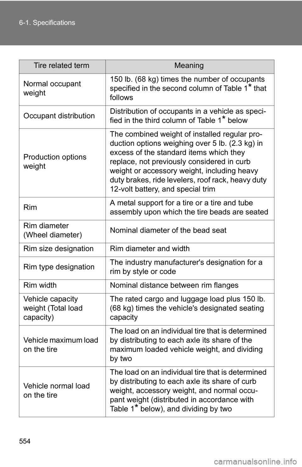
Tire related termMeaning
Normal occupant
weight 150 lb. (68 kg) times the number of occupants
specified in the second column of Table 1
* that
follows
Occupant distribution Distribution of occupants in a vehicle as speci-
fied in the third column of Table 1
* below
Production options
weight The combined weight of installed regular pro-
duction options weighing over 5 lb. (2.3 kg) in
excess of the standard items which they
replace, not previously considered in curb
weight or accessory weight, including heavy
duty brakes, ride levelers, roof rack, heavy duty
12-volt battery, and special trim
Rim A metal support for a tire or a tire and tube
assembly upon which the tire beads are seated
Rim diameter
(Wheel diameter) Nominal diameter of the bead seat
Rim size designation Rim diameter and width
Rim type designation The industry manufacturer's designation for a
rim by style or code
Rim width Nominal distance between rim flanges
Vehicle capacity
weight (Total load
capacity) The rated cargo and luggage load plus 150 lb.
(68 kg) times the vehicl
e's designated seating
capacity
Vehicle maximum load
on the tire The load on an individual tire that is determined
by distributing to each axle its share of the
maximum loaded vehicle weight, and dividing
by two
Vehicle normal load
on the tire The load on an individual tire that is determined
by distributing to each axle its share of curb
weight, accessory weight, and normal occu-
pant weight (distributed in accordance with
Ta b l e 1
* below), and dividing by two
Page 562 of 580
562
6-3. Initialization
Items to initialize
ItemWhen to initializeReference
Power back door • After reconnecting or changing the
battery
• After changing a fuse P. 7 9
The following items must be initia
lized for normal system operation
in cases such as after the 12-volt battery is reconnected, or mainte-
nance is performed on the vehicle.