Page 217 of 278

9-28
INSPECTION AND MAINTENANCE
80J21-03E
Uniform Tire Quality GradingThe U.S. National Highway Traffic Safety
Administration has developed a grading
system for evaluating the performance of
passenger car tires. The following informa-
tion will help you understand the grading
system, which applies to vehicles sold in
the U.S. Consult your SUZUKI dealer or
tire retailer for help in choosing the correct
replacement tires for your vehicle.
Quality grades can be found where appli-
cable on the tire sidewall between tread
shoulder and maximum section width. For
example:
Treadwear 200 Traction AA Temperature ADOT Quality Grades
Treadwear
Traction AA A B C
Temperature A B CAll Passenger Car Tires Must Conform To
Federal Safety Requirements in Addition
To These GradesTreadwear
The treadwear grade is a comparative rat-
ing based on the wear rate of the tire when
tested under controlled conditions on a
specified government test course. For
example, a tire graded 150 would wear one
and one-half (1 1/2) times as well on the
government course as a tire graded 100.
The relative performance of tires depends
upon the actual conditions of their use,
however and may depart significantly from
the norm due to variations in driving habits,
service practices and differences in road
characteristics and climate.
Traction – AA, A, B, C
The traction grades, from highest to low-
est, are AA, A, B and C. Those grades rep-
resent the tire’s ability to stop on wet
pavement as measured under controlled
conditions on specified government test
surfaces of asphalt and concrete. A tire
marked C may have poor traction perfor-
mance.
CAUTION
For intelligent All Wheel Drive (i-
AWD) models, replacing a tire with
one of a different size, or using differ-
ent brands among the four tires can
result in damage to the drive train.
WARNING
Replacing the wheels and tires
equipped on your vehicle with certain
combinations of aftermarket wheels
and tires can significantly change the
steering and handling characteris-
tics of your vehicle. Oversized tires
may also rub against the fender over
bumps, causing vehicle damage or
tire failure. Therefore, use only those
wheel and tire combinations
approved by SUZUKI Motor Corpora-
tion as standard or optional equip-
ment for your vehicle. For
information regarding the specified
tires, refer to the Tire Information
Label located on the driver’s side
door pillar or the “SPECIFICATIONS”
section.
CAUTION
Replacing the original tires with tires
of a different size may result in false
speedometer or odometer readings.
Check with your SUZUKI dealer
before purchasing replacement tires
that differ in size from the original
tires.
WARNING
The traction grade assigned to this
tire is based on straight-ahead brak-
ing traction tests, and does not
include acceleration, cornering,
hydroplaning or peak traction charac-
teristics.
Tires: 6
Page 218 of 278
, B and C, representing the tire’s resis-
tance to the generation of heat and its
ability")
9-29INSPECTION AND MAINTENANCE
80J21-03E
Temperature – A, B, C
The temperature grades are A (the high-
est), B and C, representing the tire’s resis-
tance to the generation of heat and its
ability to dissipate heat when tested under
controlled conditions on a specified indoor
laboratory test wheel. Sustained high tem-
perature can cause the material of the tire
to degenerate and reduce tire life, and
excessive temperature can lead to sudden
tire failure. The grade C corresponds to a
level of performance which all passenger
car tires must meet under the Federal
Motor Vehicle Safety Standard No. 109.
Grades B and A represent higher levels of
performance on the laboratory test wheel
than the minimum required by law.
Tire Rotation
54G114
To avoid uneven wear of your tires and to
prolong their life, rotate the tires as illus-
trated. Tires should be rotated as recom-
mended in the periodic maintenance
schedule. After rotation, adjust front and
rear tire pressures to the specification
listed on your vehicle’s Tire and Loading
Information Label.
WARNING
The temperature grade for this tire is
established for a tire that is properly
inflated and not overloaded. Exces-
sive speed, underinflation or exces-
sive loading, either separately or in
combination, can cause heat buildup
and possible tire failure.
WARNING
Rust or dirt on a wheel, or on the
parts to which it is fastened, can
make wheel nuts become loose after
a time. The wheel could come off and
cause an accident. When you change
a wheel, remove any rust or dirt from
places where the wheel attaches to
the vehicle. In an emergency, you can
use a cloth or a paper towel to do
this; but be sure to use a scraper or
wire brush later, if you need to, to get
all the rust or dirt off.
Tires: 6
Page 219 of 278

54G115
(1) Wear indicator
(2) Indicator location mark
Your vehicle comes equipped with the
compact spare tire. The compact sp")
9-30
INSPECTION AND MAINTENANCE
80J21-03E
Compact Spare Tire (if equipped)
54G115
(1) Wear indicator
(2) Indicator location mark
Your vehicle comes equipped with the
compact spare tire. The compact spare is
designed to save space in your storage
area, and its lighter weight makes it easier
to install if a flat tire occurs. It is only
intended for temporary emergency use,
until the conventional tire can be repaired
or replaced. The inflation pressure of the
compact spare tire should be checked at
least monthly. Use a quality pocket-type
inflation pressure gauge and set at 420
kPa (60 psi). At the same time, check that
the tire is stored securely. If it is not, tighten
it.
Note that two or more compact spare tires
should not be used on one vehicle simulta-
neously.
WARNING
The compact spare tire and wheel are
intended for temporary emergency
use only. Continuous use of this
spare can result in tire failure and
loss of control. Always observe these
precautions when using this spare:
Your vehicle will handle differently
with this temporary spare.
Do not exceed 80 km/h (50 mph)
speed.
Replace this spare with a standard
tire and wheel as soon as possible.
Use of this spare will reduce
ground clearance.
Recommended air pressure for this
spare is 420 kPa (60 psi).
Do not use tire chains on the com-
pact spare. If you must use tire
chains, rearrange the wheels so
standard tires and wheels are fitted
to the front axle.
The compact spare tire has a much
shorter tread life than the conven-
tional tires on your vehicle.
Replace the tire as soon as the
tread wear indicator appears.
When replacing the compact tire,
use a replacement tire with the
exact same size and construction.
CAUTION
For intelligent All Wheel Drive (i-
AWD) models, driving with an under-
inflated compact spare tire or over 80
km/h (50 mph) while using a compact
spare tire can result in damage to the
drive train.
Tires: 6
Page 220 of 278
 Remove the jack, tools and spare wheel
from the vehicle.
2) L")
9-31INSPECTION AND MAINTENANCE
80J21-03E
Changing WheelsSX4
80JC014
SX4 SEDAN
80JC045
To change a wheel, use the following pro-
cedure:
1) Remove the jack, tools and spare wheel
from the vehicle.
2) Loosen, but do not remove the wheel
nuts.
3) Jack up the vehicle (follow the jacking
instructions in the “EMERGENCY SER-
VICE” section in this manual).
4) Remove the wheel nuts and wheel.
5) Install the new wheel and replace the
wheel nuts with their cone shaped end
facing the wheel. Tighten each nut
snugly by hand until the wheel is
securely seated on the hub.
81A057
6) Lower the jack and fully tighten the nuts
(to the specified torque) in a crisscross
fashion with a wrench as shown in the
illustration.Snow TiresYour vehicle is equipped with all-season
tires which are designed for use in summer
and most winter conditions. For improved
traction in severe winter conditions,
SUZUKI recommends mounting radial
snow tires on all four wheels. Snow tires
must be the same size as the standard
tires. Also be sure to use the tires of the
same type and brand on all four wheels of
your vehicle.
Wheel tightening torque
85 Nm (61.5 lb-ft, 8.5 kg-m)
Tires: 6
Battery: 9
Page 221 of 278
 of automatic transaxle,
power")
9-32
INSPECTION AND MAINTENANCE
80J21-03E
GLOSSARY OF TIRE TERMINOL-
OGYAccessory Weight – the combined weight
(in excess of those standard items which
may be replaced) of automatic transaxle,
power steering, power brakes, power win-
dows, power seats, radio, and heater, to
the extent that these items are available as
factory-installed equipment (whether
installed or not).
Cold Tire Inflation Pressure – the pressure
in a tire that has been driven less than 1
mile or has been standing for three hours
or more.
Curb Weight – the weight of a motor vehi-
cle with standard equipment including the
maximum capacity of fuel, oil, and coolant,
and, if so equipped, air conditioning and
additional weight optional engine.
Intended Outboard Sidewall – (1) the side-
wall that contains a whitewall, bears white
lettering or bears manufacturer, brand,
and/or model name molding that is higher
or deeper than the same molding on the
other sidewall of the tire, or (2) the outward
facing sidewall of an asymmetrical tire that
has a particular side that must always face
outward when mounted on a vehicle.
Maximum Inflation Pressure – the maxi-
mum cold inflation pressure a tire is
designed to support in normal service.Maximum Loaded Vehicle Weight – the
sum of curb weight, accessory weight,
vehicle capacity weight (total load capac-
ity), and production options weight.
Normal Occupant Weight – 68 kilograms
times the number of occupants specified in
the second column of Table 1 (shown
below).
Occupant distribution – distribution of
occupants in a vehicle as specified in the
third column of Table 1 (shown below).
Production Options Weight – the combined
weight of those installed regular production
options weighing over 2.3 kilograms in
excess of those standard items which they
replace, not previously considered in curb
weight or accessory weight, including
heavy duty brakes, ride levelers, roof rack,
heavy duty battery, and special trim.
Recommended Inflation Pressure – the
cold tire inflation pressure recommended
by a manufacturer.
Rim – metal support for a tire or tire and
tube assembly upon which the tire beads
are seated.
Vehicle Capacity Weight – the rated cargo
and luggage load plus 68 kilograms (150
lbs) times the vehicle’s designated seating
capacity.Vehicle Maximum Load on the Tire – the
load on an individual tire that is determined
by distributing to each axle its share of the
maximum loaded vehicle weight and divid-
ing by two.
Vehicle Normal Load on the Tire – the load
on an individual tire that is determined by
distributing to each axle its share of the
curb weight, accessory weight, and normal
occupant weight (distributed in accordance
with Table 1 shown below) and dividing by
2.
TABLE 1 – Occupant Loading and Dis-
tribution For Vehicle Normal Load For
Various Designated Seating Capacities
Designated
seating capac-
ity, number of
occupantsVehicle nor-
mal load, num-
ber of
occupantsOccupant
distribution in
a normally
loaded vehicle
2 through 4 2 2 in front
5 through 10 32 in front, 1 in
second seat
Fuses: 7
Page 222 of 278

9-33INSPECTION AND MAINTENANCE
80J21-03E
Vehicle LoadingYour vehicle was designed for specific load
capacities. The load capacities of your
vehicle are indicated by the Gross Vehicle
Weight Rating (GVWR), the Gross Axle
Weight Rating (GAWR, front and rear), and
the total load capacity, the seating capac-
ity, and the cargo load capacity. The
GVWR and GAWR (front and rear) are
listed on the Safety Certification Label
which is located below the driver’s side
door latch striker. The total load capacity
and seating capacity are listed on the Tire
and Loading Information Label which is
located below the Safety Certification
Label. The cargo load capacity can be
determined as described below.
Cargo Load Capacity – Maximum weight
of cargo and luggage that the vehicle can
safely carry. Cargo load capacity is the dif-
ference between the total load capacity of
the vehicle and the total combined weight
of all vehicle occupants. Refer to “Steps for
Determining Correct Load Limit” for details
on how to determine cargo load capacity.
GVWR – Maximum permissible overall
weight of the fully loaded vehicle (including
all the occupants, accessories and cargo
plus the trailer tongue weight if towing a
trailer).
GAWR – (Front and Rear) Maximum per-
missible weight on an individual axle.Seating Capacity – Maximum number of
occupants the vehicle is designed to carry.
NOTE:
Even though the number of occupants is
within the seating capacity, you still must
make sure that you do not exceed the total
load capacity of the vehicle.
Total Load Capacity – Maximum permissi-
ble weight a vehicle can carry including the
weight of all the occupants, accessories,
cargo, plus trailer tongue weight (if towing
a trailer).
The weight of any accessories already
installed on your vehicle at the time of pur-
chase, or that you or the dealer install after
purchase, must be subtracted from the
total load capacity to determine how much
capacity remains available for occupants,
cargo, and trailer tongue weight (if towing a
trailer). Contact your dealer for further
information.
Actual weight of the loaded vehicle and
actual loads at the front and rear axles can
only be determined by weighing the vehicle
using a vehicle scale. To measure the
weight and load, try making your vehicle to
a highway weighing station, shipping com-
pany or inspection station for trucks, etc.
Compare these weights to the GVWR and
GAWR (front and rear) listed on the Safety
Certification Label. If the gross vehicle
weight or the load on either axle exceeds
these ratings, you must remove enoughweight to bring the load down to the rated
capacity.
WARNING
Never overload your vehicle. Over-
loading your vehicle can cause dam-
age to your tires and lead to poor
steering and braking which can result
in an accident. The gross vehicle
weight (sum of the weights of the
loaded vehicle, driver and passen-
gers) must never exceed the Gross
Vehicle Weight Rating (GVWR) listed
on the Safety Certification Label. In
addition, never distribute a load so
that the weight on either the front or
rear axle exceeds the Gross Axle
Weight Rating (GAWR) listed on the
Safety Certification Label.
WARNING
Always distribute cargo evenly.
To avoid personal injury or damage
to your vehicle, always secure
cargo to prevent it from shifting if
the vehicle moves suddenly.
Place heavier objects on the floor
and as far forward in the cargo area
as possible. Never pile cargo
higher than the top of the seat-
backs.
Fuses: 7
Page 223 of 278
 Locate the statement “The combined
weight of occupants and cargo should
never exceed XXX kg or XXX lbs” on
you")
9-34
INSPECTION AND MAINTENANCE
80J21-03E
Steps for Determining Correct Load
Limit
1) Locate the statement “The combined
weight of occupants and cargo should
never exceed XXX kg or XXX lbs” on
your vehicle’s placard.
2) Determine the combined weight of the
driver and passengers that will be riding
in your vehicle.
3) Subtract the combined weight of the
driver and passengers from XXX kg or
XXX lbs.
4) The resulting figure equals the available
amount of cargo and luggage load
capacity. For example, if the “XXX”
amount equals 1400 lbs and there will
be five 150 lb passengers in your vehi-
cle, the amount of available cargo and
luggage load capacity is 650 lbs (1400
– 750 (5 x 150) = 650 lbs).
5) Determine the combined weight of lug-
gage and cargo being loaded on the
vehicle. That weight may not safely
exceed the available cargo and luggage
load capacity calculated in Step 4.
6) If your vehicle will be towing a trailer,
load from your trailer will be transferred
to your vehicle. Consult this manual to
determine how this reduces the avail-
able cargo and luggage load capacity of
your vehicle.Vehicle Loading Example
As an example, suppose that the Tire and
Loading Information label on your vehicle
indicates that your vehicle’s total load
capacity is 950 lbs. If you were to drive
your vehicle with one passenger, and the
total combined weight of you and your pas-
senger was 350 lbs, then the cargo and
luggage capacity of your vehicle would be
600 lbs (950 – 350 = 600 lbs).
If you later added 2 more passengers, hav-
ing a combined weight of 325 lbs, the
cargo and luggage capacity of your vehicle
would be reduced from 600 lbs to 275 lbs
(600 – 325 = 275 lbs). As you can see, as
the number and combined weight of vehi-
cle occupants increase, the vehicle’s cargo
and luggage capacity decreases.
Suppose again, that you were to take a trip
in your vehicle with the same three pas-
sengers described above, and you decided
to tow a trailer having a trailer tongue
weight of 75 lbs. The cargo and luggage
capacity would be reduced again, to 200
lbs (275 – 75 = 200 lbs).Determining Compatibility of Tire and
Vehicle Load Limits
The tires on your vehicle, when they are
inflated to the recommended tire inflation
pressure, have a load-carrying capacity
that is greater than the load that will be on
the tires when the vehicle is at its GVWR
or GAWR limit. Never use replacement
tires that have a load-carrying capacity
less than the original tires on your vehicle.
Tire load-carrying capacity information is
molded into the tire sidewall typically
shown as “Max. Load”. Use of replacement
tires with a lower load-carrying capacity
than the original tires, or failure to keep the
tires inflated to recommended tire pres-
sure, may reduce the GVWR or GAWR
limit of your vehicle.
NOTE:
Use of replacement tires with a higher
load-carrying capacity than the original
tires, or using a tire inflation pressure
higher than the recommended tire inflation
pressure, will not increase the GVWR or
GAWR limit of your vehicle.
Headlight Aiming:
Bulb Replacement: 7
Page 224 of 278

9-35INSPECTION AND MAINTENANCE
80J21-03E
Battery
60A269
Your vehicle is equipped with a battery that
requires infrequent maintenance. You will
never have to add water. You should, how-
ever, periodically check the battery, battery
terminals and battery hold-down bracket
for corrosion. Remove corrosion using a
stiff brush and ammonia mixed with water,
or baking soda mixed with water. After
removing corrosion, rinse with clean water.
The test indicator on the top of the battery
provides information on the condition of
the battery.
If your vehicle is not going to be driven for
a month or longer, disconnect the cable
from the negative terminal of the battery to
help prevent discharge.
FusesYour vehicle has three types of fuses, as
described below:
Main Fuse – The main fuse takes current
directly from the battery.
Primary Fuses – These fuses are between
the main fuse and individual fuses, and are
for electrical load groups.
Individual Fuses – These fuses are for indi-
vidual electrical circuits.
For details on protected circuits, refer to
the “Fuses and Protected Circuits” section
in this manual.
WARNING
Batteries produce flammable hydro-
gen gas. Keep flames and sparks
away from the battery or an explosion
may occur. Never smoke when work-
ing near the battery.
WARNING
When checking or servicing the bat-
tery, disconnect the negative cable.
Be careful not to cause a short circuit
by allowing metal objects to contact
the battery posts and the vehicle at
the same time.EXAMPLE
WARNING
To avoid harm to yourself or damage
to your vehicle or battery, follow the
jump starting instructions in the
“EMERGENCY SERVICE” section of
this manual if it is necessary to jump
start your vehicle.
WARNING
Battery posts, terminals and related
accessories contain lead and lead
compounds. Wash hands after han-
dling.
Bulb Replacement: 7
 1
1 2
2 3
3 4
4 5
5 6
6 7
7 8
8 9
9 10
10 11
11 12
12 13
13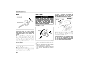 14
14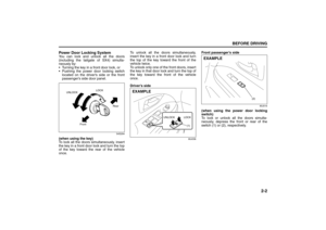 15
15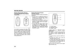 16
16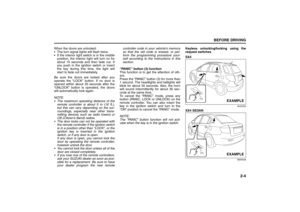 17
17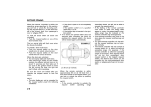 18
18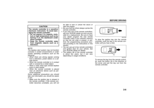 19
19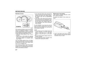 20
20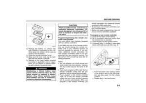 21
21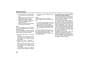 22
22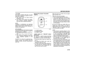 23
23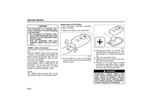 24
24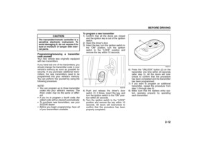 25
25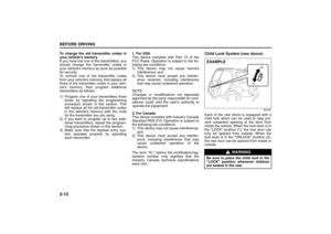 26
26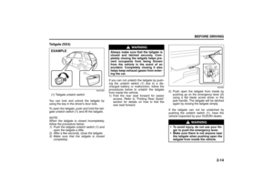 27
27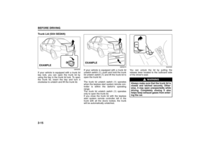 28
28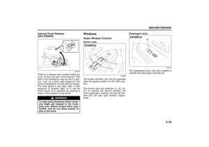 29
29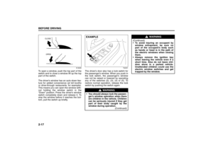 30
30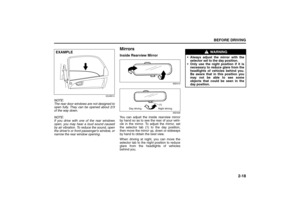 31
31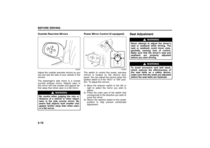 32
32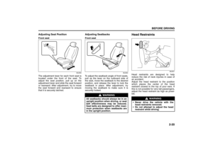 33
33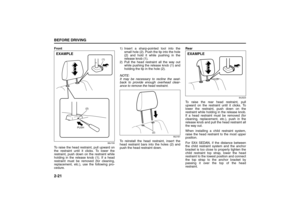 34
34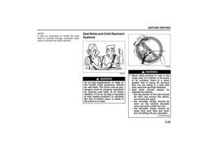 35
35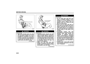 36
36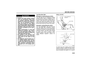 37
37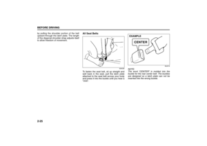 38
38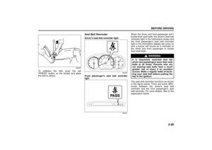 39
39 40
40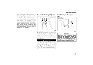 41
41 42
42 43
43 44
44 45
45 46
46 47
47 48
48 49
49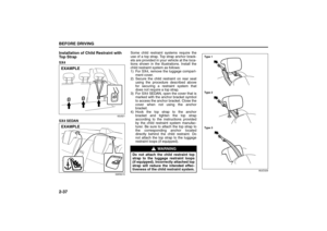 50
50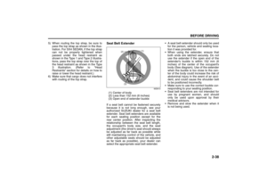 51
51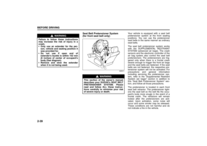 52
52 53
53 54
54 55
55 56
56 57
57 58
58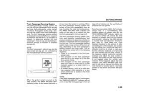 59
59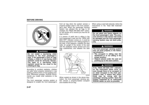 60
60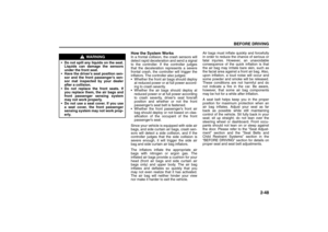 61
61 62
62 63
63 64
64 65
65 66
66 67
67 68
68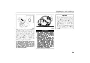 69
69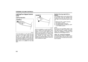 70
70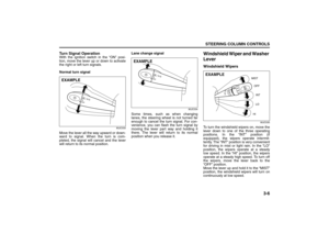 71
71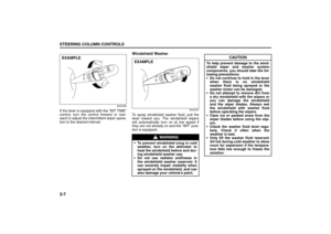 72
72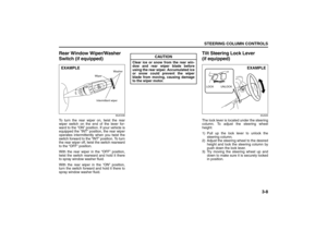 73
73 74
74 75
75 76
76 77
77 78
78 79
79 80
80 81
81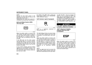 82
82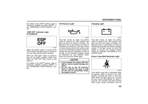 83
83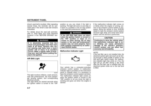 84
84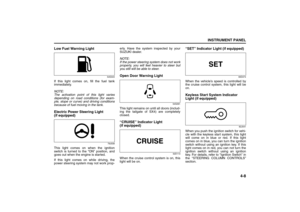 85
85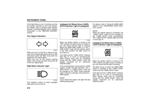 86
86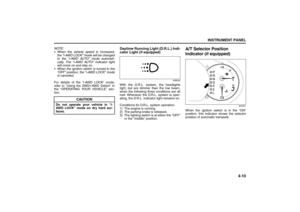 87
87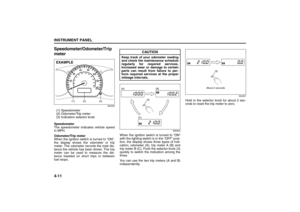 88
88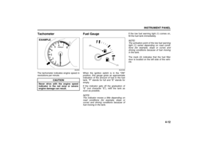 89
89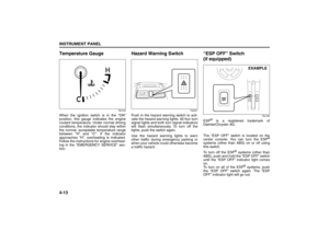 90
90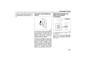 91
91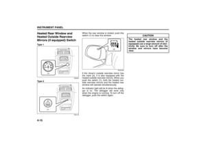 92
92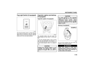 93
93 94
94 95
95 96
96 97
97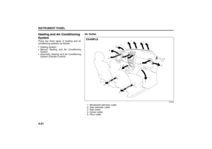 98
98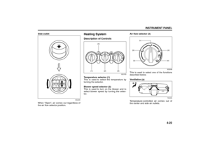 99
99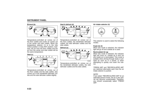 100
100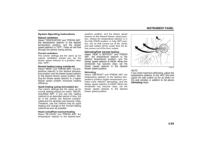 101
101 102
102 103
103 104
104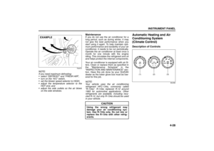 105
105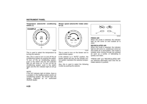 106
106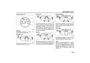 107
107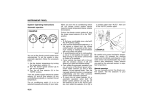 108
108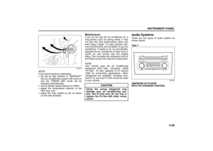 109
109 110
110 111
111 112
112 113
113 114
114 115
115 116
116 117
117 118
118 119
119 120
120 121
121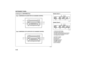 122
122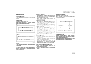 123
123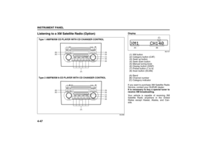 124
124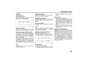 125
125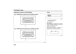 126
126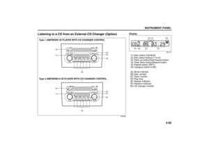 127
127 128
128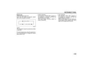 129
129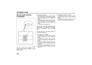 130
130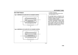 131
131 132
132 133
133 134
134 135
135 136
136 137
137 138
138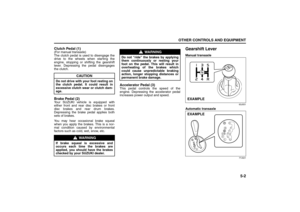 139
139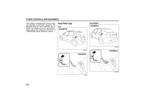 140
140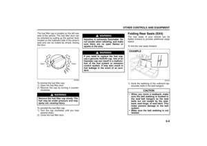 141
141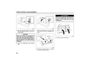 142
142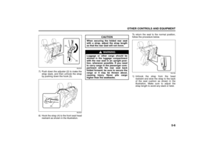 143
143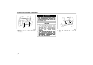 144
144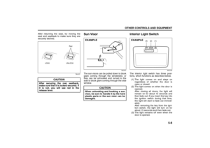 145
145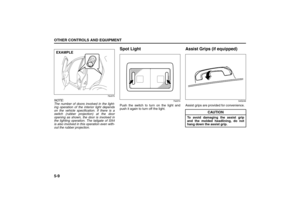 146
146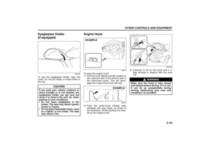 147
147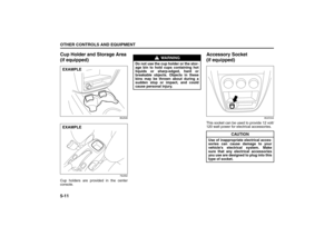 148
148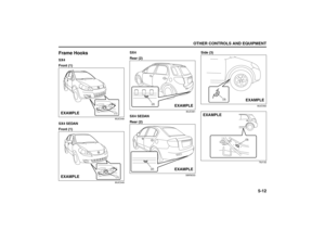 149
149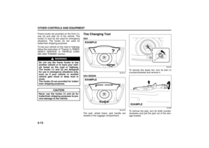 150
150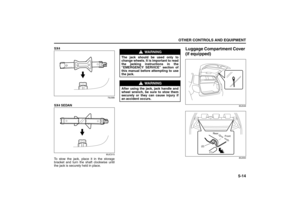 151
151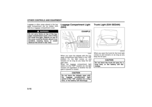 152
152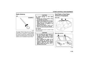 153
153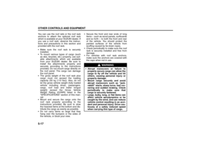 154
154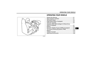 155
155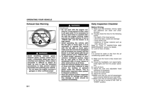 156
156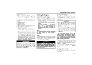 157
157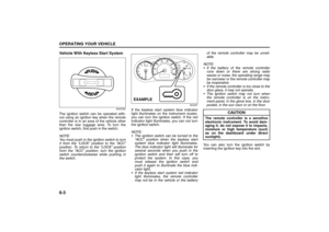 158
158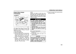 159
159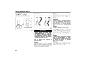 160
160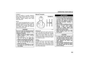 161
161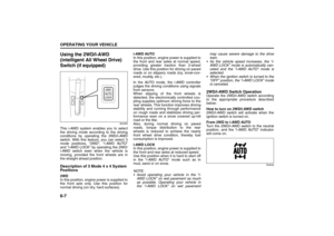 162
162 163
163 164
164 165
165 166
166 167
167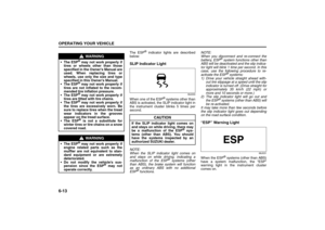 168
168 169
169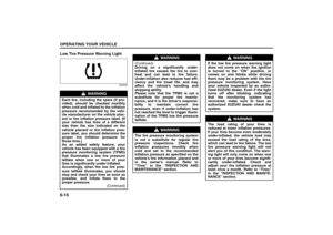 170
170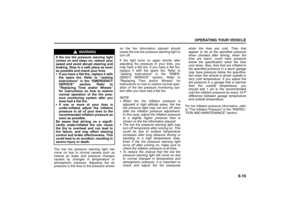 171
171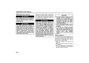 172
172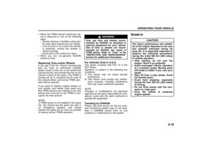 173
173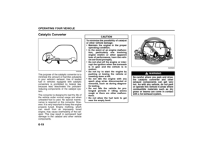 174
174 175
175 176
176 177
177 178
178 179
179 180
180 181
181 182
182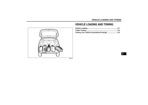 183
183 184
184 185
185 186
186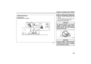 187
187 188
188 189
189 190
190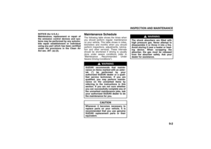 191
191 192
192 193
193 194
194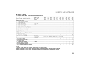 195
195 196
196 197
197 198
198 199
199 200
200 201
201 202
202 203
203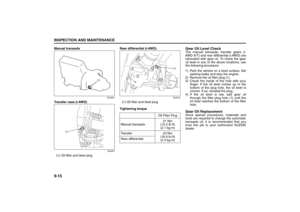 204
204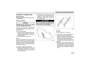 205
205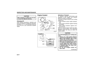 206
206 207
207 208
208 209
209 210
210 211
211 212
212 213
213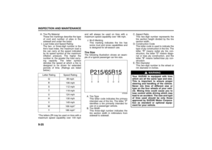 214
214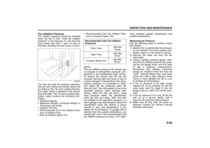 215
215 216
216 217
217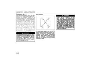 218
218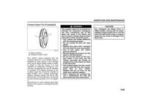 219
219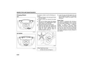 220
220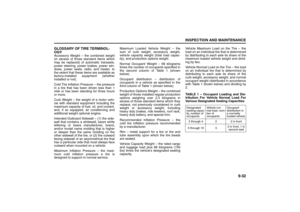 221
221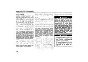 222
222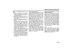 223
223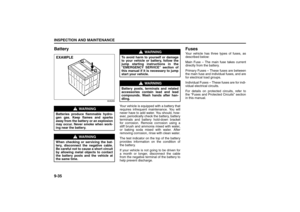 224
224 225
225 226
226 227
227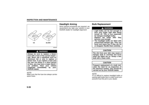 228
228 229
229 230
230 231
231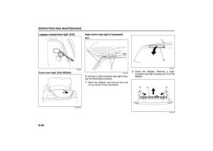 232
232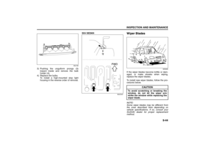 233
233 234
234 235
235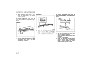 236
236 237
237 238
238 239
239 240
240 241
241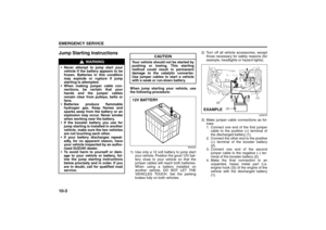 242
242 243
243 244
244 245
245 246
246 247
247 248
248 249
249 250
250 251
251 252
252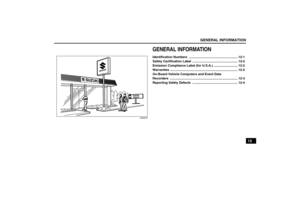 253
253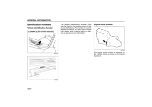 254
254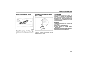 255
255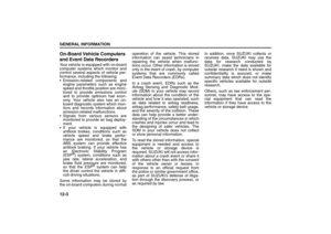 256
256 257
257 258
258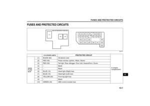 259
259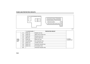 260
260 261
261 262
262 263
263 264
264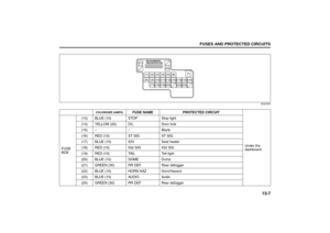 265
265 266
266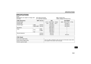 267
267 268
268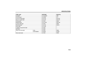 269
269 270
270 271
271 272
272 273
273 274
274 275
275 276
276 277
277