Page 150 of 278

5-13OTHER CONTROLS AND EQUIPMENT
80J21-03E
Frame hooks are provided on the front (1),
rear (2) and side (3) of the vehicle. The
hooks (1) and (2) are used for emergency
situations. The hooks (3) are used for
trailer/train shipping purposes.
To tow your vehicle on the road or highway,
follow the instruction of “Towing” in “EMER-
GENCY SERVICE” or “VEHICLE LOAD-
ING AND TOWING” section.
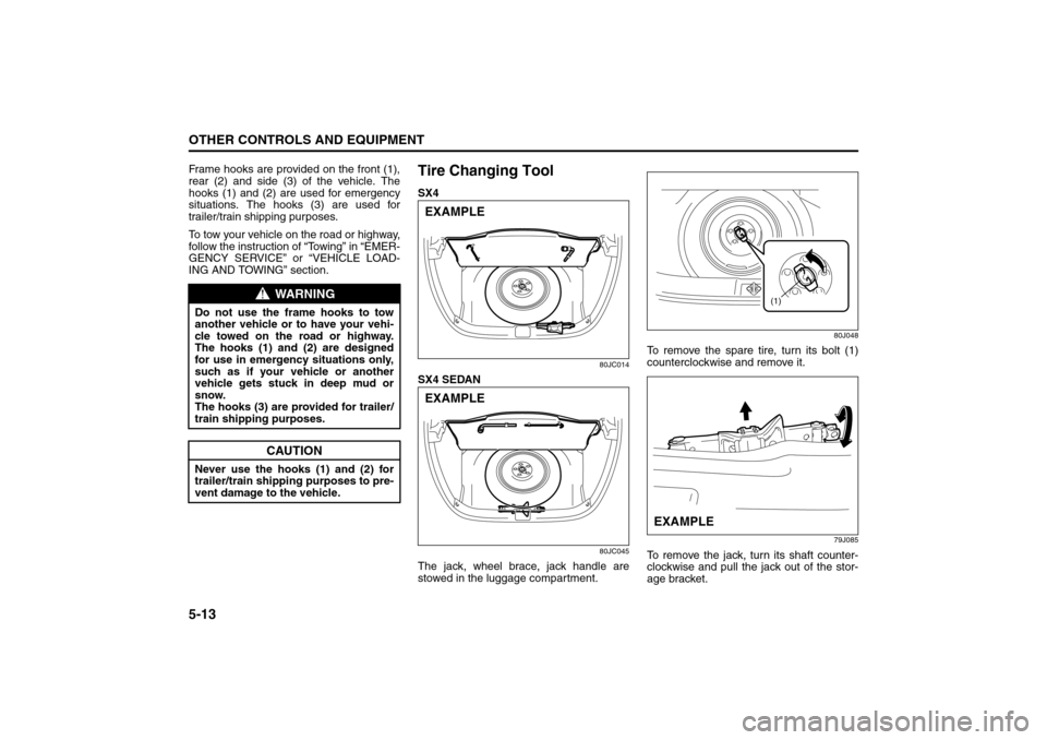
Tire Changing ToolSX4
80JC014
SX4 SEDAN
80JC045
The jack, wheel brace, jack handle are
stowed in the luggage compartment.
80J048
To remove the spare tire, turn its bolt (1)
counterclockwise and remove it.
79J085
To remove the jack, turn its shaft counter-
clockwise and pull the jack out of the stor-
age bracket.
WARNING
Do not use the frame hooks to tow
another vehicle or to have your vehi-
cle towed on the road or highway.
The hooks (1) and (2) are designed
for use in emergency situations only,
such as if your vehicle or another
vehicle gets stuck in deep mud or
snow.
The hooks (3) are provided for trailer/
train shipping purposes.
CAUTION
Never use the hooks (1) and (2) for
trailer/train shipping purposes to pre-
vent damage to the vehicle.
EXAMPLEEXAMPLE
(1)
EXAMPLE
Cup Holder and Storage Area: 3
Page 151 of 278
5-14
OTHER CONTROLS AND EQUIPMENT
80J21-03E
SX4
79J086
SX4 SEDAN
80JC015
To stow the jack, place it in the storage
bracket and turn the shaft clockwise until
the jack is securely held in place.
Luggage Compartment Cover
(if equipped)
80J049
80J050
WARNING
The jack should be used only to
change wheels. It is important to read
the jacking instructions in the
“EMERGENCY SERVICE” section of
this manual before attempting to use
the jack.
WARNING
After using the jack, jack handle and
wheel wrench, be sure to stow them
securely or they can cause injury if
an accident occurs.
(1) (2)
Front Rear
Accessory Socket: 8
Frame Hooks: 5, 6
Page 153 of 278

5-16
OTHER CONTROLS AND EQUIPMENT
80J21-03E
Radio AntennaSX4
63J055
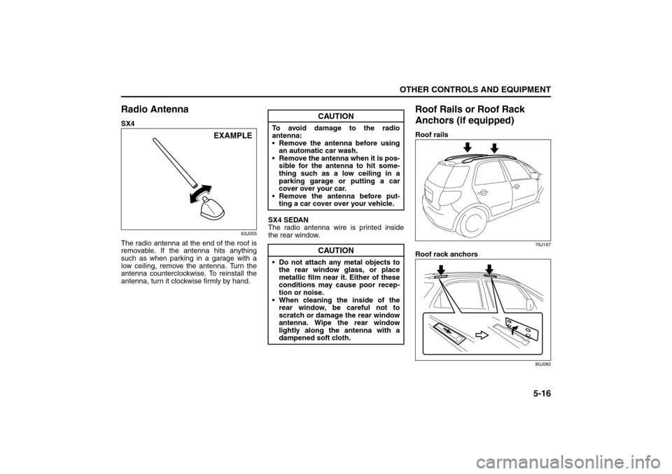
The radio antenna at the end of the roof is
removable. If the antenna hits anything
such as when parking in a garage with a
low ceiling, remove the antenna. Turn the
antenna counterclockwise. To reinstall the
antenna, turn it clockwise firmly by hand.SX4 SEDAN
The radio antenna wire is printed inside
the rear window.
Roof Rails or Roof Rack
Anchors (if equipped)Roof rails
79J167
Roof rack anchors
80J082
EXAMPLE
CAUTION
To avoid damage to the radio
antenna:
Remove the antenna before using
an automatic car wash.
Remove the antenna when it is pos-
sible for the antenna to hit some-
thing such as a low ceiling in a
parking garage or putting a car
cover over your car.
Remove the antenna before put-
ting a car cover over your vehicle.
CAUTION
Do not attach any metal objects to
the rear window glass, or place
metallic film near it. Either of these
conditions may cause poor recep-
tion or noise.
When cleaning the inside of the
rear window, be careful not to
scratch or damage the rear window
antenna. Wipe the rear window
lightly along the antenna with a
dampened soft cloth.
Page 158 of 278

6-3OPERATING YOUR VEHICLE
80J21-03E
Vehicle With Keyless Start System
80JC002
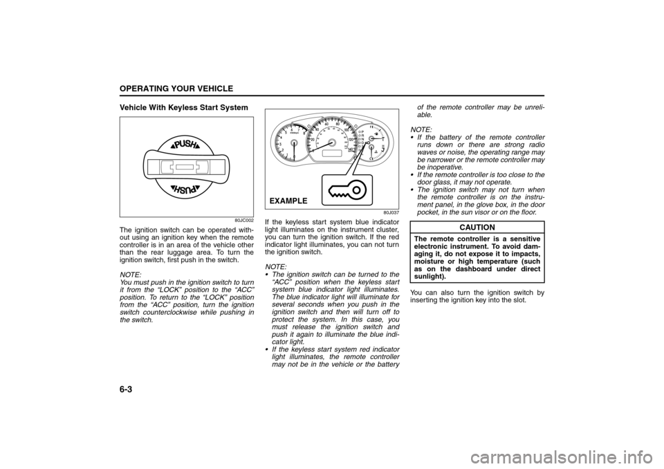
The ignition switch can be operated with-
out using an ignition key when the remote
controller is in an area of the vehicle other
than the rear luggage area. To turn the
ignition switch, first push in the switch.
NOTE:
You must push in the ignition switch to turn
it from the “LOCK” position to the “ACC”
position. To return to the “LOCK” position
from the “ACC” position, turn the ignition
switch counterclockwise while pushing in
the switch.
80J037
If the keyless start system blue indicator
light illuminates on the instrument cluster,
you can turn the ignition switch. If the red
indicator light illuminates, you can not turn
the ignition switch.
NOTE:
The ignition switch can be turned to the
“ACC” position when the keyless start
system blue indicator light illuminates.
The blue indicator light will illuminate for
several seconds when you push in the
ignition switch and then will turn off to
protect the system. In this case, you
must release the ignition switch and
push it again to illuminate the blue indi-
cator light.
If the keyless start system red indicator
light illuminates, the remote controller
may not be in the vehicle or the batteryof the remote controller may be unreli-
able.
NOTE:
If the battery of the remote controller
runs down or there are strong radio
waves or noise, the operating range may
be narrower or the remote controller may
be inoperative.
If the remote controller is too close to the
door glass, it may not operate.
The ignition switch may not turn when
the remote controller is on the instru-
ment panel, in the glove box, in the door
pocket, in the sun visor or on the floor.
You can also turn the ignition switch by
inserting the ignition key into the slot.EXAMPLE
CAUTION
The remote controller is a sensitive
electronic instrument. To avoid dam-
aging it, do not expose it to impacts,
moisture or high temperature (such
as on the dashboard under direct
sunlight).
Engine Block Heater: 1
Page 202 of 278

9-13INSPECTION AND MAINTENANCE
80J21-03E
Replace the Oil Filter
60A198
1) Remove the engine under cover.
2) Using an oil filter wrench, turn the oil fil-
ter counterclockwise and remove it.
3) Using a clean rag, wipe off the mount-
ing surface on the engine where the
new filter will be seated.
4) Smear a little engine oil around the rub-
ber gasket of the new oil filter.
5) Screw on the new filter by hand until the
filter gasket contacts the mounting sur-
face.
54G093
(1) Oil filter
(2) 3/4 turn
6) Tighten the filter 3/4 turn from the point
of contact with the mounting surface (or
to the specified torque) using an oil filter
wrench.
Refill with Oil and Check for Leaks1) Pour oil through the filler hole and
install the filler cap.
For the approximate capacity of the oil,
refer to the “Capacities” item in the
“SPECIFICATIONS” section.
2) Start the engine and look carefully for
leaks at the oil filter and drain plug. Run
the engine at various speeds for at least
5 minutes.
3) Stop the engine and wait about 5 min-
utes. Check the oil level again and add
oil if necessary. Check for leaks again.
CAUTION
To tighten the oil filter properly, it is
important to accurately identify the
position at which the filter gasket
first contacts the mounting surface.
Tightening torque specification
14 Nm (10.0 lb-ft, 1.4 kg-m)
CAUTION
To prevent oil leakage, make sure
that the oil filter is tight, but do not
overtighten it.
CAUTION
When replacing the oil filter, it is rec-
ommended that you use a genuine
SUZUKI replacement filter. If you use
an after-market filter, make sure it is
of equivalent quality and carefully fol-
low the manufacturer’s instructions
and precautions.
Automatic Transaxle Fluid: 10
Engine Coolant: 1, 2
Page 229 of 278
9-40
INSPECTION AND MAINTENANCE
80J21-03E
Center Interior Light (if equipped)
60G115
Pull down the lens by using a plain screw
driver covered with a soft cloth as shown.
To install it, simply push it back in.
The bulb can be removed by simply pulling
it out. When replacing the bulb, make sure
that the contact springs are holding the
bulb securely.
Headlights
65D149
54G121
Open the engine hood. Remove the cou-
pler and the rubber cover. Then unhook
the bulb holding spring and replace the
bulb.
Other General LightsBulb holder
54G123
(1) Removal
(2) Installation
To remove a bulb holder from a light hous-
ing, turn the holder counterclockwise and
pull it out. To install the holder, push the
holder in and turn it clockwise.
(1)
(1) (2)(2)
EXAMPLE
Wiper Blades: 3
Page 230 of 278
9-41INSPECTION AND MAINTENANCE
80J21-03E
Bulb
54G124
(3) Removal
(4) Installation
There are two types of bulb, “Full glass
type” (1) and “Glass/metal type” (2).
To remove and install a full glass type bulb
(1), simply pull out or push in the bulb.
To remove a glass metal type bulb (2) from
a bulb holder, push in the bulb and turn it
counterclockwise. To install a new bulb,
push it in and turn it clockwise.
You can access the individual bulb or bulb
holders as follows.Front parking light (1)
Front turn signal light (2)
79J012
Front fog light (if equipped)
SX4
80J006
SX4 SEDAN
55KS039
(1)
(2) (3)
(4)EXAMPLE
(1)
(2)
Wiper Blades: 3
Page 241 of 278

10-2
EMERGENCY SERVICE
80J21-03E
80J085
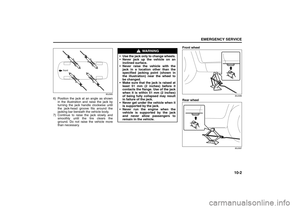
6) Position the jack at an angle as shown
in the illustration and raise the jack by
turning the jack handle clockwise until
the jack-head groove fits around the
jacking bar beneath the vehicle body.
7) Continue to raise the jack slowly and
smoothly until the tire clears the
ground. Do not raise the vehicle more
than necessary.Front wheel
80J086
Rear wheel
80J087
front
WARNING
Use the jack only to change wheels.
Never jack up the vehicle on an
inclined surface.
Never raise the vehicle with the
jack in a location other than the
specified jacking point (shown in
the illustration) near the wheel to
be changed.
Make sure that the jack is raised at
least 51 mm (2 inches) before it
contacts the flange. Use of the jack
when it is within 51 mm (2 inches)
of being fully collapsed may result
in failure of the jack.
Never get under the vehicle when it
is supported by the jack.
Never run the engine when the
vehicle is supported by the jack
and never allow passengers to
remain in the vehicle.
Jacking Instructions: 5