2008 SUZUKI SX4 clock
[x] Cancel search: clockPage 28 of 278
2-15BEFORE DRIVING
80J21-03E
Trunk Lid (SX4 SEDAN)
55KS005
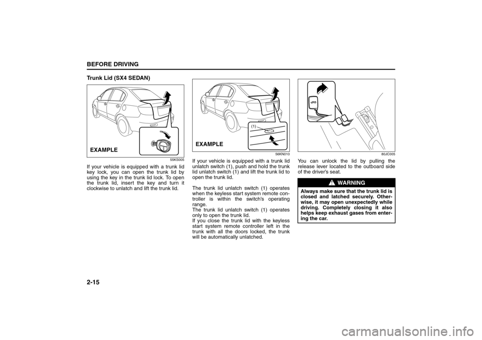
If your vehicle is equipped with a trunk lid
key lock, you can open the trunk lid by
using the key in the trunk lid lock. To open
the trunk lid, insert the key and turn it
clockwise to unlatch and lift the trunk lid.
56KN010
If your vehicle is equipped with a trunk lid
unlatch switch (1), push and hold the trunk
lid unlatch switch (1) and lift the trunk lid to
open the trunk lid.
The trunk lid unlatch switch (1) operates
when the keyless start system remote con-
troller is within the switch’s operating
range.
The trunk lid unlatch switch (1) operates
only to open the trunk lid.
If you close the trunk lid with the keyless
start system remote controller left in the
trunk with all the doors locked, the trunk
will be automatically unlatched.
80JC005
You can unlock the lid by pulling the
release lever located to the outboard side
of the driver’s seat.
EXAMPLE
(1)
EXAMPLE
WARNING
Always make sure that the trunk lid is
closed and latched securely. Other-
wise, it may open unexpectedly while
driving. Completely closing it also
helps keep exhaust gases from enter-
ing the car.
Seat Belts and Child Restraint Systems: 3
Page 67 of 278
3-2
STEERING COLUMN CONTROLS
80J21-03E
60A300S
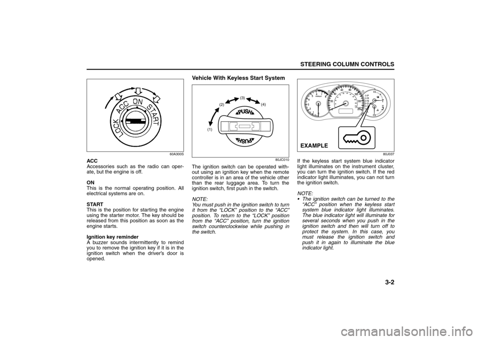
ACC
Accessories such as the radio can oper-
ate, but the engine is off.
ON
This is the normal operating position. All
electrical systems are on.
START
This is the position for starting the engine
using the starter motor. The key should be
released from this position as soon as the
engine starts.
Ignition key reminder
A buzzer sounds intermittently to remind
you to remove the ignition key if it is in the
ignition switch when the driver’s door is
opened.
Vehicle With Keyless Start System
80JC010
The ignition switch can be operated with-
out using an ignition key when the remote
controller is in an area of the vehicle other
than the rear luggage area. To turn the
ignition switch, first push in the switch.
NOTE:
You must push in the ignition switch to turn
it from the “LOCK” position to the “ACC”
position. To return to the “LOCK” position
from the “ACC” position, turn the ignition
switch counterclockwise while pushing in
the switch.
80J037
If the keyless start system blue indicator
light illuminates on the instrument cluster,
you can turn the ignition switch. If the red
indicator light illuminates, you can not turn
the ignition switch.
NOTE:
The ignition switch can be turned to the
“ACC” position when the keyless start
system blue indicator light illuminates.
The blue indicator light will illuminate for
several seconds when you push in the
ignition switch and then will turn off to
protect the system. In this case, you
must release the ignition switch and
push it in again to illuminate the blue
indicator light.
(1)(2)(3)
(4)
EXAMPLE
Ignition Switch: 8
Page 68 of 278

3-3STEERING COLUMN CONTROLS
80J21-03E
If the keyless start system red indicator
light illuminates, the remote controller
may not be in the vehicle or the battery
of the remote controller may be unreli-
able.
NOTE:
If the battery of the remote controller
runs down or there are strong radio
waves or noise, the operating range may
be narrower or the remote controller may
be inoperative.
If the remote controller is too close to the
door glass, it may not operate.
The ignition switch may not turn when
the remote controller is on the instru-
ment panel, in the glove box, in the door
pocket, in the sun visor or on the floor.
You can also turn the ignition switch by
inserting the ignition key into the slot.The ignition switch has the following four
positions:
LOCK (1)
This is the normal parking position. It is the
only position in which the key can be
removed. It locks the ignition, and prevents
normal use of the steering wheel.
For vehicles with an automatic transaxle,
the gearshift lever must be in the “P” (Park)
position to turn the key to the “LOCK” posi-
tion.
To release the steering lock, turn the igni-
tion switch clockwise to one of the other
positions. If you have trouble turning the
ignition switch to unlock the steering, try
turning the steering wheel slightly to the
right or left while turning the switch.
NOTE:
You must push the ignition switch in to turn
it to the “ACC” position. Also you must
push the ignition switch in to return it to the
“LOCK” position.
ACC (2)
Accessories such as the radio can oper-
ate, but the engine is off.
ON (3)
This is the normal operating position. All
electrical systems are on.START (4)
This is the position for starting the engine
using the starter motor. The switch should
be released from this position as soon as
the engine starts.
Ignition switch reminder
(When using the keyless start system)
A buzzer sounds intermittently to remind
you to return the ignition switch to the
“LOCK” position if it is in the “ACC” position
when the driver’s door is opened.
Ignition key reminder
(When using the ignition key)
A buzzer sounds intermittently to remind
you to remove the ignition key if it is in the
ignition switch when the driver’s door is
opened.
CAUTION
The remote controller is a sensitive
electronic instrument. To avoid dam-
aging the remote controller:
Do not expose it to impacts, mois-
ture or high temperature such as by
leaving it on the dashboard under
direct sunlight.
Keep the remote controller away
from magnetic objects such as a
television.
Lighting/Turn Signal Control Lever: 8
Page 69 of 278

3-4
STEERING COLUMN CONTROLS
80J21-03E
62J083
If the gearshift lever can not be shifted out
of “P” (Park) in the normal way, removing
the cover (1) and pushing the release but-
ton using a key or some other flat end
object with the key in the “ON” or “ACC”
position will permit movement of the gear-
shift lever out of “P” (see “If You Can Not
Shift Automatic Transaxle Gearshift Lever
Out of “P” (PARK)” in the INDEX). The
gearshift lever can be moved back to “P”
without pushing the release button.
To release the steering lock, insert the key
or use the keyless start system and turn
the ignition switch clockwise to one of the
other positions. If you have trouble turning
the key to unlock the steering, try turning
the steering wheel slightly to the right or
left while turning the key.
81A297S
(1)
WARNING
For manual transaxle vehicles,
never remove the ignition key while
the vehicle is moving. The steering
wheel will lock and you will not be
able to steer the vehicle.
Always remove the ignition key
when leaving the vehicle even if a
short time. Also do not leave chil-
dren or pets alone in a parked vehi-
cle. Unattended children could
cause accidental movement of the
vehicle or could tamper with power
windows. Children or pets could
suffer from heatstroke in warm or
hot weather, which could result in
severe injury or even death.
CAUTION
Do not turn the starter motor for
more than 15 seconds at a time. If
the engine does not start, wait 15
seconds before trying again. If the
engine does not start after several
attempts, check the fuel and igni-
tion systems or consult your
SUZUKI dealer.
Do not leave the ignition switch in
the “ON” position if the engine is
not running or the battery will dis-
charge.
Lighting/Turn Signal Control Lever: 8
Windshield Wiper and Washer Lever: 8
Page 94 of 278
4-17INSTRUMENT PANEL
80J21-03E
Information Display
80J035
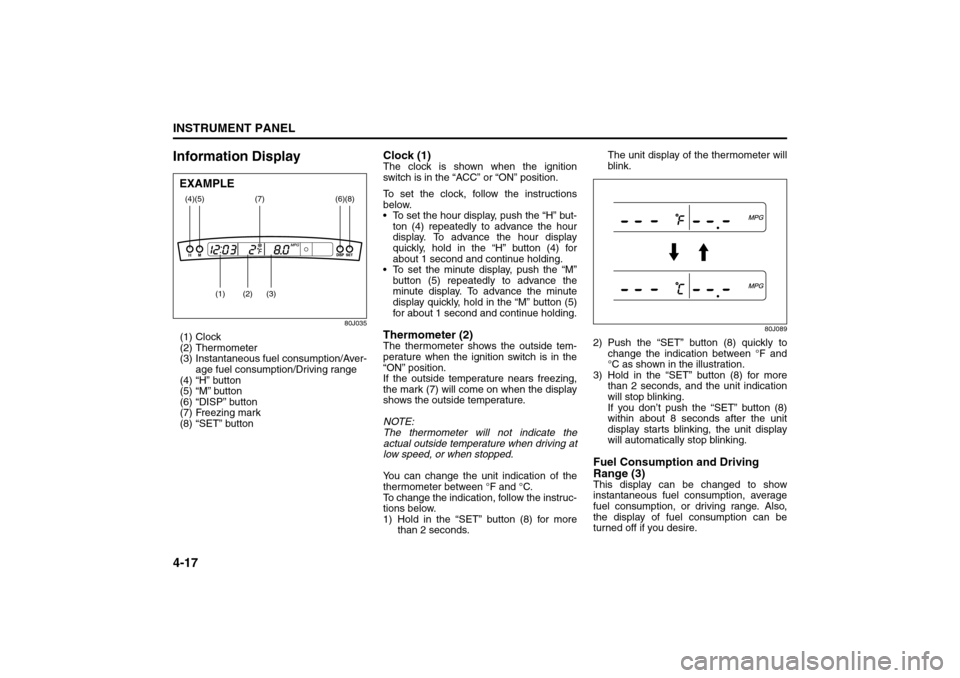
(1) Clock
(2) Thermometer
(3) Instantaneous fuel consumption/Aver-
age fuel consumption/Driving range
(4) “H” button
(5) “M” button
(6) “DISP” button
(7) Freezing mark
(8) “SET” button
Clock (1)The clock is shown when the ignition
switch is in the “ACC” or “ON” position.
To set the clock, follow the instructions
below.
To set the hour display, push the “H” but-
ton (4) repeatedly to advance the hour
display. To advance the hour display
quickly, hold in the “H” button (4) for
about 1 second and continue holding.
To set the minute display, push the “M”
button (5) repeatedly to advance the
minute display. To advance the minute
display quickly, hold in the “M” button (5)
for about 1 second and continue holding.Thermometer (2)The thermometer shows the outside tem-
perature when the ignition switch is in the
“ON” position.
If the outside temperature nears freezing,
the mark (7) will come on when the display
shows the outside temperature.
NOTE:
The thermometer will not indicate the
actual outside temperature when driving at
low speed, or when stopped.
You can change the unit indication of the
thermometer between °F and °C.
To change the indication, follow the instruc-
tions below.
1) Hold in the “SET” button (8) for more
than 2 seconds.The unit display of the thermometer will
blink.
80J089
2) Push the “SET” button (8) quickly to
change the indication between °F and
°C as shown in the illustration.
3) Hold in the “SET” button (8) for more
than 2 seconds, and the unit indication
will stop blinking.
If you don’t push the “SET” button (8)
within about 8 seconds after the unit
display starts blinking, the unit display
will automatically stop blinking.Fuel Consumption and Driving
Range (3)This display can be changed to show
instantaneous fuel consumption, average
fuel consumption, or driving range. Also,
the display of fuel consumption can be
turned off if you desire.
(4)
(2)
(1)
(3)
(5)
(8)
(7)
(6)
EXAMPLE
Heating and Air Conditioning System: 4
Page 113 of 278

4-36
INSTRUMENT PANEL
80J21-03E
Turning power on/off
Press the power on/off knob (1).
The unit starts in the function mode it was
in when the power was turned off last.
Adjusting the volume
Turn the volume control knob (1).
Turning it clockwise increases the volume;
turning it counterclockwise decreases the
volume.
NOTE:
While driving, adjust the volume to an
extent that sound and/or noise coming
from outside the car can be heard.Adjusting bass/treble/balance/fader
1) Press the tone/balance/fader control
knob (2).
Each time it is pressed, sound adjust-
ment is changed as follows:
66J224
2) Turn the tone/balance/fader control
knob (2) to adjust the sound.Adjusting the AVC (Auto volume con-
trol)
The Automatic Volume Control (AVC) func-
tion automatically adjusts (increases/
decreases) the sound volume in accor-
dance with vehicle speed. The AVC control
is provided with three selectable levels
(LEVEL OFF, 1, 2, 3). The range of volume
adjustment increases together with the
LEVEL number,
1) Press the tone/balance/fader control
knob (2) until the AVC adjustment mode
is selected.
2) Turn the tone/balance/fader control
knob (2) to select the desired AVC
adjustment level. (Initial setting: LEVEL
2)
Adjusting the contrast of the display
1) Press the tone/balance/fader/control
knob (2) and preset button 5 (3), preset
button 6 (4) simultaneously.
2) To adjust the contrast of the display,
turn the power on/off knob (1).
Cancel the dimmer condition
Each time you press the power on/off knob
(1) for two seconds with the lighting switch
on, the background brightness of the audio
display will switch between normal and
dimmed.
Bass adjustment (BASS 0)
Treble adjustment (TREBLE 0)
Balance adjustment (BALANCE 0)
Fader adjustment (FADER 0)
AVC adjustment (AVC LEVEL 2)
Original mode
Audio Systems:
Page 115 of 278
4-38
INSTRUMENT PANEL
80J21-03E
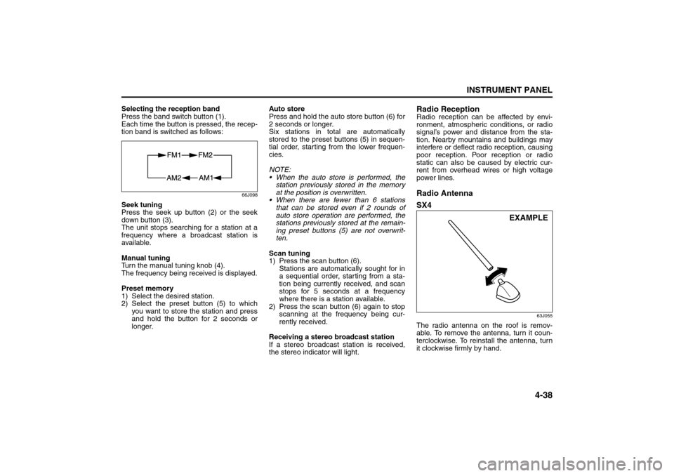
Selecting the reception band
Press the band switch button (1).
Each time the button is pressed, the recep-
tion band is switched as follows:
66J098
Seek tuning
Press the seek up button (2) or the seek
down button (3).
The unit stops searching for a station at a
frequency where a broadcast station is
available.
Manual tuning
Turn the manual tuning knob (4).
The frequency being received is displayed.
Preset memory
1) Select the desired station.
2) Select the preset button (5) to which
you want to store the station and press
and hold the button for 2 seconds or
longer.Auto store
Press and hold the auto store button (6) for
2 seconds or longer.
Six stations in total are automatically
stored to the preset buttons (5) in sequen-
tial order, starting from the lower frequen-
cies.
NOTE:
When the auto store is performed, the
station previously stored in the memory
at the position is overwritten.
When there are fewer than 6 stations
that can be stored even if 2 rounds of
auto store operation are performed, the
stations previously stored at the remain-
ing preset buttons (5) are not overwrit-
ten.
Scan tuning
1) Press the scan button (6).
Stations are automatically sought for in
a sequential order, starting from a sta-
tion being currently received, and scan
stops for 5 seconds at a frequency
where there is a station available.
2) Press the scan button (6) again to stop
scanning at the frequency being cur-
rently received.
Receiving a stereo broadcast station
If a stereo broadcast station is received,
the stereo indicator will light.
Radio ReceptionRadio reception can be affected by envi-
ronment, atmospheric conditions, or radio
signal’s power and distance from the sta-
tion. Nearby mountains and buildings may
interfere or deflect radio reception, causing
poor reception. Poor reception or radio
static can also be caused by electric cur-
rent from overhead wires or high voltage
power lines.Radio Antenna
SX4
63J055
The radio antenna on the roof is remov-
able. To remove the antenna, turn it coun-
terclockwise. To reinstall the antenna, turn
it clockwise firmly by hand.
EXAMPLE
Audio Systems:
Page 141 of 278
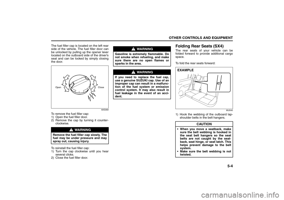
5-4
OTHER CONTROLS AND EQUIPMENT
80J21-03E
The fuel filler cap is located on the left rear
side of the vehicle. The fuel filler door can
be unlocked by pulling up the opener lever
located on the outboard side of the driver’s
seat and can be locked by simply closing
the door.
60G069
To remove the fuel filler cap:
1) Open the fuel filler door.
2) Remove the cap by turning it counter-
clockwise.
To reinstall the fuel filler cap:
1) Turn the cap clockwise until you hear
several clicks.
2) Close the fuel filler door.
Folding Rear Seats (SX4)The rear seats of your vehicle can be
folded forward to provide additional cargo
space.
To fold the rear seats forward:
80J040
1) Hook the webbing of the outboard lap-
shoulder belts in the belt hangers.
WARNING
Remove the fuel filler cap slowly. The
fuel may be under pressure and may
spray out, causing injury.Open Close
WARNING
Gasoline is extremely flammable. Do
not smoke when refueling, and make
sure there are no open flames or
sparks in the area.
WARNING
If you need to replace the fuel cap,
use a genuine SUZUKI cap. Use of an
improper cap can result in a malfunc-
tion of the fuel system or emission
control system. It may also result in
fuel leakage in the event of an acci-
dent.
CAUTION
When you move a seatback, make
sure the belt webbing is hooked in
the seat belt hangers so the seat
belts are not caught by the seat-
back, seat hinge, or seat latch. This
helps prevent damage to the belt
system.
Make sure the belt webbing is not
twisted.EXAMPLE
Fuel Filler Cap: 5
Folding Rear Seats: 3