2008 SUZUKI SWIFT Mode
[x] Cancel search: ModePage 502 of 1496
Downloaded from www.Manualslib.com manuals search engine 4A-4 Brake Control System and Diagnosis:
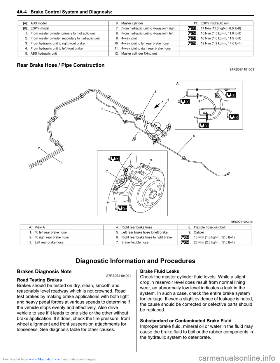
Rear Brake Hose / Pipe ConstructionS7RS0B4101003
Diagnostic Information and Procedures
Brakes Diagnosis NoteS7RS0B4104001
Road Testing Brakes
Brakes should be tested on dry, clean, smooth and
reasonably level roadway which is not crowned. Road
test brakes by making brake applications with both light
and heavy pedal forces at vari ous speeds to determine if
the vehicle stops evenly and effectively. Also drive
vehicle to see if it leads to one side or the other without
brake application. If it does, check the tire pressure, front
wheel alignment and front suspension attachments for
looseness. See diagnosis table for other causes. Brake Fluid Leaks
Check the master cylinder fl
uid levels. While a slight
drop in reservoir level does result from normal lining
wear, an abnormally low leve l indicates a leak in the
system. In such a case, chec k the entire brake system
for leakage. If even a slight ev idence of leakage is noted,
the cause should be corrected or defective parts should
be replaced.
Substandard or Contaminated Brake Fluid
Improper brake fluid, mineral oil or water in the fluid may
cause the brake fluid to boil or the rubber components in
the hydraulic system to deteriorate.
[A]: ABS model 6. Master cylinder13. ESP® hydraulic unit
[B]: ESP ® model 7. From hydraulic unit to 4-way joint right : 11 N⋅m (11.0 kgf-m, 8.0 lb-ft)
1. From master cylinder primary to hydraulic unit 8. From hydraulic unit to 4-way joint left: 15 N⋅m (1.5 kgf-m, 11.0 lb-ft)
2. From master cylinder secondary to hydraulic unit 9. 4-way joint: 16 N⋅m (1.6 kgf-m, 11.5 lb-ft)
3. From hydraulic unit to right front brake 10.4-way joint to left rear brake hose : 19 N⋅m (1.9 kgf-m, 14.0 lb-ft)
4. From hydraulic unit to left front brake 11. 4-way joint to right rear brake hose
5. ABS hydraulic unit 12. Master cylinder fixing nut
I6RS0C410003-01
A: View A4. Right rear brake hose8. Flexible hose joint bolt
1. To left rear brake hose 5. Left rear brake hose to left brake9. Caliper
2. To right rear brake hose 6. Right rear brake hose to right brake: 16 N⋅m (1.6 kgf-m, 12.0 lb-ft)
3. Left rear brake hose 7. Brake flexible hose: 23 N⋅m (2.3 kgf-m, 17.0 lb-ft)
Page 510 of 1496
Downloaded from www.Manualslib.com manuals search engine 4A-12 Brake Control System and Diagnosis:
Master Cylinder Assembly Removal and
Installation
S7RS0B4106011
CAUTION!
Do not allow brake fluid to get on painted
surfaces. Painted surfaces will be damaged
by brake fluid, flush it with water immediately
if any fluid is spilled.
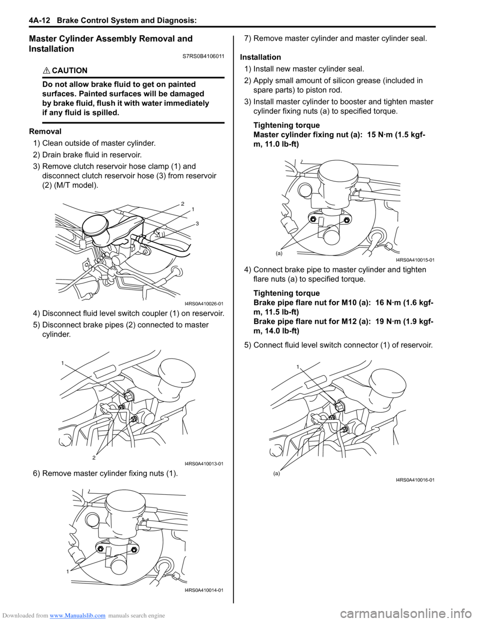
Removal
1) Clean outside of master cylinder.
2) Drain brake fluid in reservoir.
3) Remove clutch reservoir hose clamp (1) and disconnect clutch reservoir hose (3) from reservoir
(2) (M/T model).
4) Disconnect fluid level switch coupler (1) on reservoir.
5) Disconnect brake pipes (2) connected to master cylinder.
6) Remove master cylinder fixing nuts (1). 7) Remove master cylinder and master cylinder seal.
Installation 1) Install new master cylinder seal.
2) Apply small amount of silic on grease (included in
spare parts) to piston rod.
3) Install master cylinder to booster and tighten master cylinder fixing nuts (a) to specified torque.
Tightening torque
Master cylinder fixing nut (a): 15 N·m (1.5 kgf-
m, 11.0 lb-ft)
4) Connect brake pipe to master cylinder and tighten flare nuts (a) to specified torque.
Tightening torque
Brake pipe flare nut for M10 (a): 16 N·m (1.6 kgf-
m, 11.5 lb-ft)
Brake pipe flare nut for M12 (a): 19 N·m (1.9 kgf-
m, 14.0 lb-ft)
5) Connect fluid level switch connector (1) of reservoir.
3
2
1
I4RS0A410026-01
1
2
I4RS0A410013-01
1
I4RS0A410014-01
(a)I4RS0A410015-01
1
(a)
I4RS0A410016-01
Page 511 of 1496
Downloaded from www.Manualslib.com manuals search engine Brake Control System and Diagnosis: 4A-13
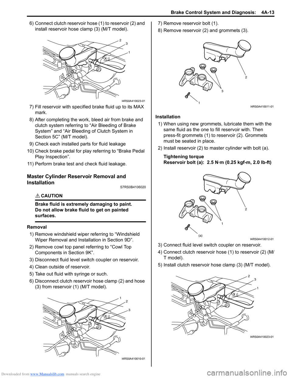
6) Connect clutch reservoir hose (1) to reservoir (2) and install reservoir hose clamp (3) (M/T model).
7) Fill reservoir with specified brake fluid up to its MAX
mark.
8) After completing the work, bleed air from brake and clutch system referring to “Air Bleeding of Brake
System” and “Air Bleeding of Clutch System in
Section 5C” (M/T model).
9) Check each installed parts for fluid leakage
10) Check brake pedal for play referring to “Brake Pedal Play Inspection”.
11) Perform brake test and check fluid leakage.
Master Cylinder Reservoir Removal and
Installation
S7RS0B4106020
CAUTION!
Brake fluid is extremely damaging to paint.
Do not allow brake fluid to get on painted
surfaces.
Removal 1) Remove windshield wiper referring to “Windshield Wiper Removal and Insta llation in Section 9D”.
2) Remove cowl top panel referring to “Cowl Top Components in Section 9K”.
3) Disconnect fluid level s witch coupler on reservoir.
4) Clean outside of reservoir.
5) Take out fluid with syringe or such.
6) Disconnect clutch reservoir hose clamp (2) and hose (3) from reservoir (1) (M/T model). 7) Remove reservoir bolt (1).
8) Remove reservoir (2) and grommets (3).
Installation 1) When using new grommets, lubricate them with the same fluid as the one to fill reservoir with. Then
press-fit grommets (1) to reservoir (2). Grommets
must be seated in place.
2) Install reservoir (2) to master cylinder with bolt (a).
Tightening torque
Reservoir bolt (a): 2.5 N·m (0.25 kgf-m, 2.0 lb-ft)
3) Connect fluid level switch coupler on reservoir.
4) Connect clutch reservoir hose (1) to reservoir (2) (M/ T model).
5) Install clutch reservoir hose clamp (3) (M/T model).
1
2
3
I4RS0A410023-01
3
1
2
I4RS0A410010-01
1 2
3I4RS0A410011-01
1 2
(a)
I4RS0A410012-01
1
2
3
I4RS0A410023-01
Page 512 of 1496
Downloaded from www.Manualslib.com manuals search engine 4A-14 Brake Control System and Diagnosis:
6) Fill reservoir with specified fluid.
7) After completing the work, bleed air from brake and clutch system referring to “Air Bleeding of Brake
System” and “Air Bleeding of Clutch System in
Section 5C” (M/T model).
8) Install cowl top panel referring to “Cowl Top Components in Section 9K”.
9) Install windshield wiper referring to “Windshield
Wiper Removal and Insta llation in Section 9D”.
10) Perform brake test and check each installed part for fluid leakage.
Master Cylinder Assembly Disassembly and
Assembly
S7RS0B4106013
Disassembly
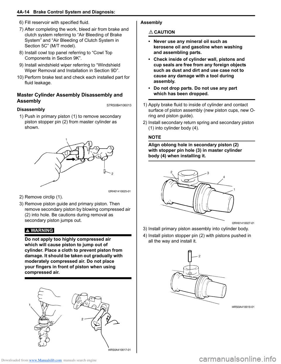
1) Push in primary piston (1) to remove secondary
piston stopper pin (2) from master cylinder as
shown.
2) Remove circlip (1).
3) Remove piston guide and primary piston. Then remove secondary piston by blowing compressed air
(2) into hole. Be cautions during removal as
secondary piston jumps out.
WARNING!
Do not apply too highly compressed air
which will cause piston to jump out of
cylinder. Place a cloth to prevent piston from
damage. It should be taken out gradually with
moderately compressed air. Do not place
your fingers in front of piston when using
compressed air.
Assembly
CAUTION!
• Never use any mineral oil such as kerosene oil and gasoline when washing
and assembling parts.
• Check inside of cylinder wall, pistons and cup seals are free from any foreign objects
such as dust and dirt and use case not to
cause any damage with a tool during
assembly.
• Do not drop parts. Do not use any part which has been dropped.
1) Apply brake fluid to inside of cylinder and contact surface of piston assembly (new piston cups, new O-
ring and piston guide).
2) Install secondary return spring and secondary piston (1) into cylinder body (4).
NOTE
Align oblong hole in secondary piston (2)
with stopper pin hole (3) in master cylinder
body (4) when installing it.
3) Install primary piston assembly into cylinder body.
4) Install piston stopper pin (2) with pistons pushed in all the way and install it.
I2RH01410025-01
I4RS0A410017-01
I2RH01410027-01
I4RS0A410018-01
Page 520 of 1496
Downloaded from www.Manualslib.com manuals search engine 4B-4 Front Brakes:
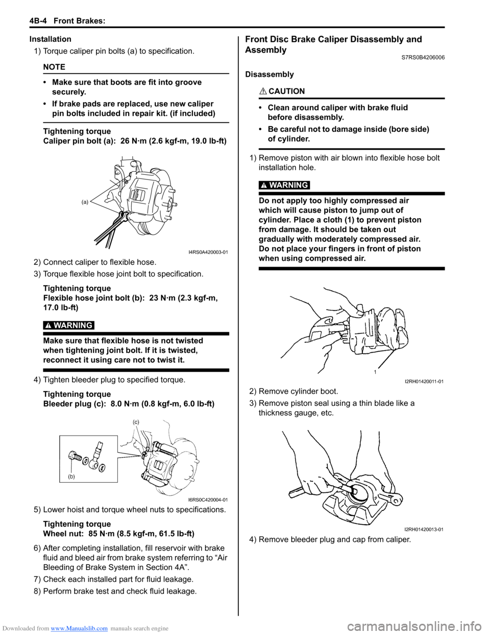
Installation1) Torque caliper pin bolts (a) to specification.
NOTE
• Make sure that boots are fit into groove securely.
• If brake pads are replaced, use new caliper pin bolts included in repair kit. (if included)
Tightening torque
Caliper pin bolt (a): 26 N·m (2.6 kgf-m, 19.0 lb-ft)
2) Connect caliper to flexible hose.
3) Torque flexible hose jo int bolt to specification.
Tightening torque
Flexible hose joint bolt (b): 23 N·m (2.3 kgf-m,
17.0 lb-ft)
WARNING!
Make sure that flexible hose is not twisted
when tightening joint bolt. If it is twisted,
reconnect it using care not to twist it.
4) Tighten bleeder plug to specified torque. Tightening torque
Bleeder plug (c): 8.0 N·m (0.8 kgf-m, 6.0 lb-ft)
5) Lower hoist and torque wheel nuts to specifications. Tightening torque
Wheel nut: 85 N·m (8.5 kgf-m, 61.5 lb-ft)
6) After completing installation, fill reservoir with brake
fluid and bleed air from brake system referring to “Air
Bleeding of Brake System in Section 4A”.
7) Check each installed part for fluid leakage.
8) Perform brake test and check fluid leakage.
Front Disc Brake Caliper Disassembly and
Assembly
S7RS0B4206006
Disassembly
CAUTION!
• Clean around caliper with brake fluid before disassembly.
• Be careful not to damage inside (bore side) of cylinder.
1) Remove piston with air blown into flexible hose bolt installation hole.
WARNING!
Do not apply too highly compressed air
which will cause piston to jump out of
cylinder. Place a cloth (1) to prevent piston
from damage. It should be taken out
gradually with moderately compressed air.
Do not place your fingers in front of piston
when using compressed air.
2) Remove cylinder boot.
3) Remove piston seal using a thin blade like a thickness gauge, etc.
4) Remove bleeder plug and cap from caliper.
(a)
I4RS0A420003-01
I6RS0C420004-01
I2RH01420011-01
I2RH01420013-01
Page 567 of 1496
Downloaded from www.Manualslib.com manuals search engine ABS: 4E-28
Repair Instructions
ABS Hydraulic Unit Operation CheckS7RS0B4506001
1) Check that basic brake system other than ABS is in good condition.
2) Check that battery voltage is 11 V or higher.
3) Lift up vehicle.
4) Set transmission to neutral and release parking brake.
5) Turn each wheel gradually by hand to check if brake dragging occurs. If it does, correct.
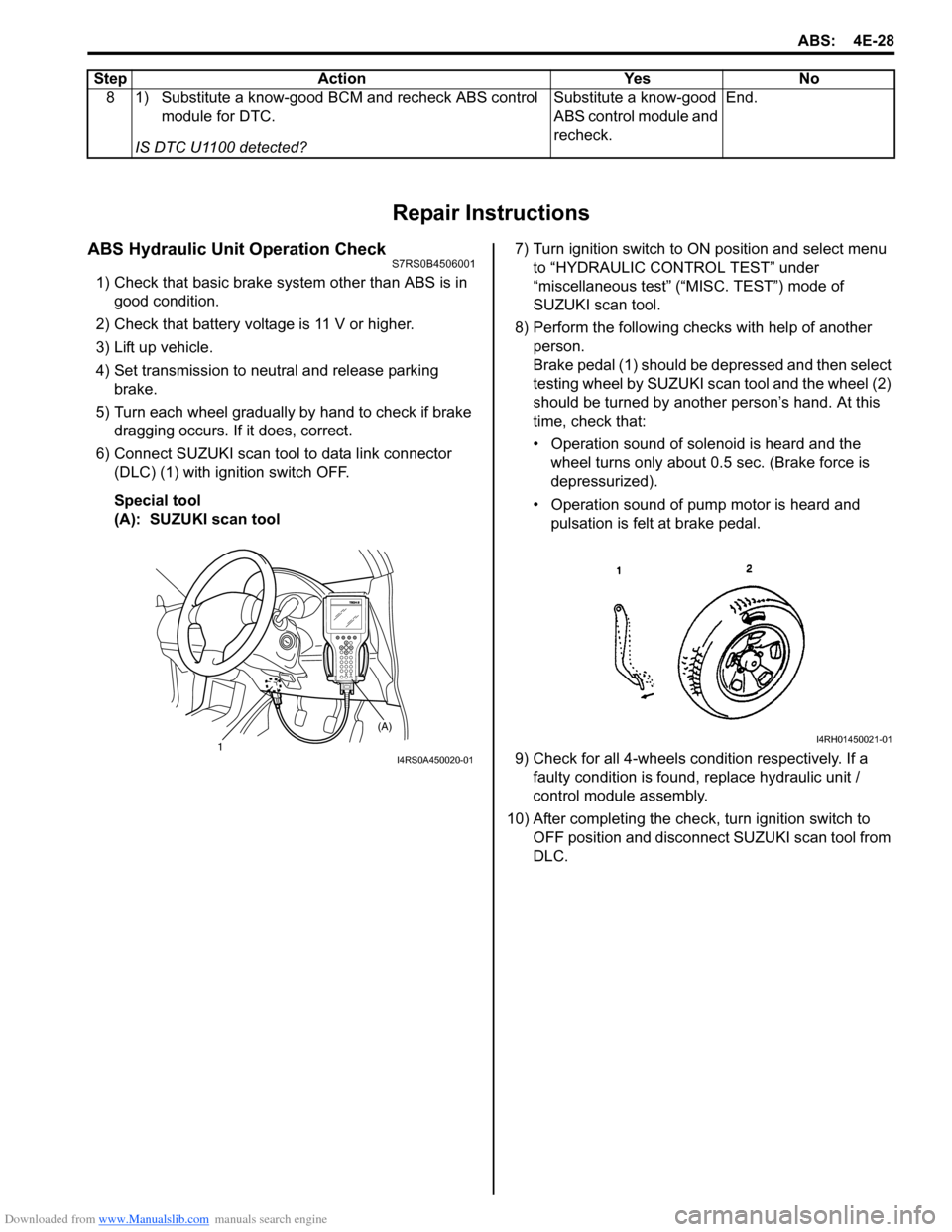
6) Connect SUZUKI scan tool to data link connector (DLC) (1) with ignition switch OFF.
Special tool
(A): SUZUKI scan tool 7) Turn ignition switch to ON position and select menu
to “HYDRAULIC CONTROL TEST” under
“miscellaneous test” (“MISC. TEST”) mode of
SUZUKI scan tool.
8) Perform the following checks with help of another person.
Brake pedal (1) should be depressed and then select
testing wheel by SUZUKI scan tool and the wheel (2)
should be turned by another person’s hand. At this
time, check that:
• Operation sound of solenoid is heard and the wheel turns only about 0.5 sec. (Brake force is
depressurized).
• Operation sound of pump motor is heard and pulsation is felt at brake pedal.
9) Check for all 4-wheels co ndition respectively. If a
faulty condition is found, replace hydraulic unit /
control module assembly.
10) After completing the check, turn ignition switch to OFF position and disconnect SUZUKI scan tool from
DLC.
8 1) Substitute a know-good BCM and recheck ABS control
module for DTC.
IS DTC U1100 detected? Substitute a know-good
ABS control module and
recheck.
End.
Step Action Yes No
1 (A)I4RS0A450020-01
I4RH01450021-01
Page 576 of 1496
Downloaded from www.Manualslib.com manuals search engine 4F-2 Electronic Stability Program:
Perform sensor calibration according to “Sensor Calibration”.
Precautions in Speedometer Test or Other TestsS7RS0B4600005
When performing speedometer or other tests using speedometer tester or chassis dynamometer, ESP® function must
be deactivated by ESP ® OFF switch or using SUZUKI scan to ol to complete the tests correctly.
When using SUZUKI scan tool, set to the “MISC. TEST” mode to stop the ESP ® function. Refer to SUZUKI scan tool
operator's manual for further details.
General Description
Electronic Stability Program DescriptionS7RS0B4601006
Electronic Stability Program (ESP ®) is an auxiliary function to enable the vehicle to av oid a danger safely while the
vehicle is running, stopping or turning.
Electronic Stability Program (ESP ®) consists of following functions.
ESP ® is a registered trademark of Daimler Chrysler AG.
Antilock Brake System (ABS)
This system prevents tire locking which may occur when br ake is applied suddenly or on slippery roads. With this
function, as the vehicle body is kept in the stable state an d tires unlocked, the driver can avoid any obstacle by turning
the steering wheel.
Electronic Brake force Distribution (EBD)
This function distributes braking force of front and rear wheels properly according to the vehicle load condition.
With this function, the braking force of the front and rear wheels is controlled for the optimum effect to secure the
maximum braking force regardless of the loadage.
Traction Control System (TCS)
This system controls the engine and brake to prevent the dr iving wheels from spinning at the time of starting and
accelerating. Particularly, this fu nction is helpful for safe driving on muddy or icy roads. When ESP ® control module
detects wheel spinning using information from the yaw rate sensor and wheel speed sensor, it lower the engine torque
by closing the electronic controlled thro ttle and controlling ignition. At the same time, brake is applied to the spinning
tire.
Stability Control
This function controls the vehicle body in the stable state by controlling the engine and braking so as to prevent the
vehicle from over-steering or under-steering while turning.
When under-steering occurs, this function lowers the engine torque and applies brake to the inner rear wheel in the
vehicle forward direction so as to pr event the vehicle from moving outward.
When over-steering occurs, this function applies brake to the outer front wheel in the vehicle forward direction so as to
prevent the vehicle from moving inward. Sensor Procedures required calibration
Steering angle sensor • Power is not su pplied to steering angle sensor. (battery, fuse and/or connector is
removed.)
• Steering angle sensor is replaced.
• Power is not supplied to ESP ® control module. (battery, fuse and/or connector is
removed.)
• ESP® hydraulic unit / control module assembly is replaced.
Master cylinder pressure sensor • ESP® hydraulic unit / control module assembly is removed or replaced.
Yaw rate / G sensor assembly • Yaw rate / G sensor assembly is removed or replaced.
• ESP® hydraulic unit / control module assembly is replaced.
Page 577 of 1496
Downloaded from www.Manualslib.com manuals search engine Electronic Stability Program: 4F-3
Electronic Stability Program ConstructionS7RS0B4601007
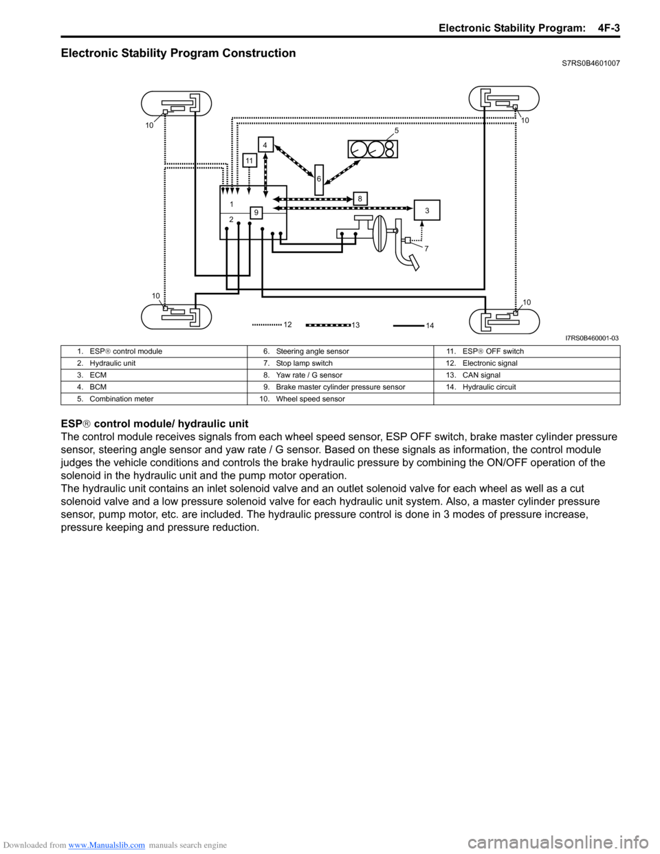
ESP® control module/ hydraulic unit
The control module receives signals from each wheel speed sensor, ESP O FF switch, brake master cylinder pressure
sensor, steering angle sensor and yaw rate / G sensor. Ba sed on these signals as information, the control module
judges the vehicle conditions and controls the brake hydraulic pressure by combining the ON/OFF operation of the
solenoid in the hydraulic unit and the pump motor operation.
The hydraulic unit contains an inlet so lenoid valve and an outlet solenoid valve for each wheel as well as a cut
solenoid valve and a low pressure solenoid valve for each hydraulic unit system. Also, a master cylinder pressure
sensor, pump motor, etc. are included. The hydraulic pre ssure control is done in 3 modes of pressure increase,
pressure keeping and pressure reduction.
7
1
2 3
4
5
6
8
9
10
1010
10
1312
11
14
I7RS0B460001-03
1. ESP ® control module 6. Steering angle sensor 11. ESP ® OFF switch
2. Hydraulic unit 7. Stop lamp switch 12. Electronic signal
3. ECM 8. Yaw rate / G sensor 13. CAN signal
4. BCM 9. Brake master cylinder pre ssure sensor 14. Hydraulic circuit
5. Combination meter 10. Wheel speed sensor