2008 SUZUKI SWIFT Mode
[x] Cancel search: ModePage 301 of 1496
![SUZUKI SWIFT 2008 2.G Service Workshop Manual Downloaded from www.Manualslib.com manuals search engine Engine Mechanical: 1D-16
Engine Mountings ComponentsS7RS0B1406010
I6RS0C140014-02
[A]: View A5. Engine left mounting No.2 bracket 12. To vehic](/manual-img/20/7607/w960_7607-300.png "SUZUKI SWIFT 2008 2.G Service Workshop Manual Downloaded from www.Manualslib.com manuals search engine Engine Mechanical: 1D-16
Engine Mountings ComponentsS7RS0B1406010
I6RS0C140014-02
[A]: View A5. Engine left mounting No.2 bracket 12. To vehic")
Downloaded from www.Manualslib.com manuals search engine Engine Mechanical: 1D-16
Engine Mountings ComponentsS7RS0B1406010
I6RS0C140014-02
[A]: View A5. Engine left mounting No.2 bracket 12. To vehicle body
[B]: For A/T model 6. Engine rear mounting : 65 N⋅m (6.5 kgf-m, 47.0 lb-ft)
F: Vehicle front 7. Engine rear mounting No.1 bracket : 55 N⋅m (5.5 kgf-m, 40.0 lb-ft)
1. Engine right mounting bracket 8. Engine rear mounting No.2 bracket : 85 N⋅m (8.5 kgf-m, 61.5 lb-ft)
2. Engine right mounting 9. Engine rear mounting stiffener : 25 N⋅m (2.5 kgf-m, 18.0 lb-ft)
3. Engine left mounting No.1 bracket 10. Yellow mark : Do not reuse.
4. Engine left mounting 11. Front mark
Page 302 of 1496
Downloaded from www.Manualslib.com manuals search engine 1D-17 Engine Mechanical:
Engine Assembly Removal and InstallationS7RS0B1406011
NOTE
After replacing electric throttle body
assembly, perform calibration of throttle
valve referring to “Electric Throttle Body
System Calibration in Section 1C”.
Removal1) Relieve fuel pressure according to “Fuel Pressure Relief Procedure in Section 1G”.
2) Disconnect negative and pos itive cable at battery.
3) Remove battery and tray.
4) Remove engine hood after disconnecting windshield washer hose.
5) Remove right and left side engine under covers.
6) Remove A/C compressor belt by referring to “Compressor Drive Belt Remo val and Installation in
Section 7B” or “Compressor Drive Belt Removal and
Installation in Section 7B”.
7) Drain engine oil, transaxle oil and coolant.
8) Remove cowl top plate referring to “Cowl Top Components in Section 9K”.
9) Remove air cleaner assembly referring to “Air Cleaner Components”.
10) With hose connected, detach A/C compressor from its bracket (A/C model) referring to “Compressor
Assembly Removal and Installation in Section 7B” or
“Compressor Assembly Removal and Installation in
Section 7B”.
CAUTION!
Suspend removed A/C compressor at a place
where no damage will be caused during
removal and installation of engine assembly.
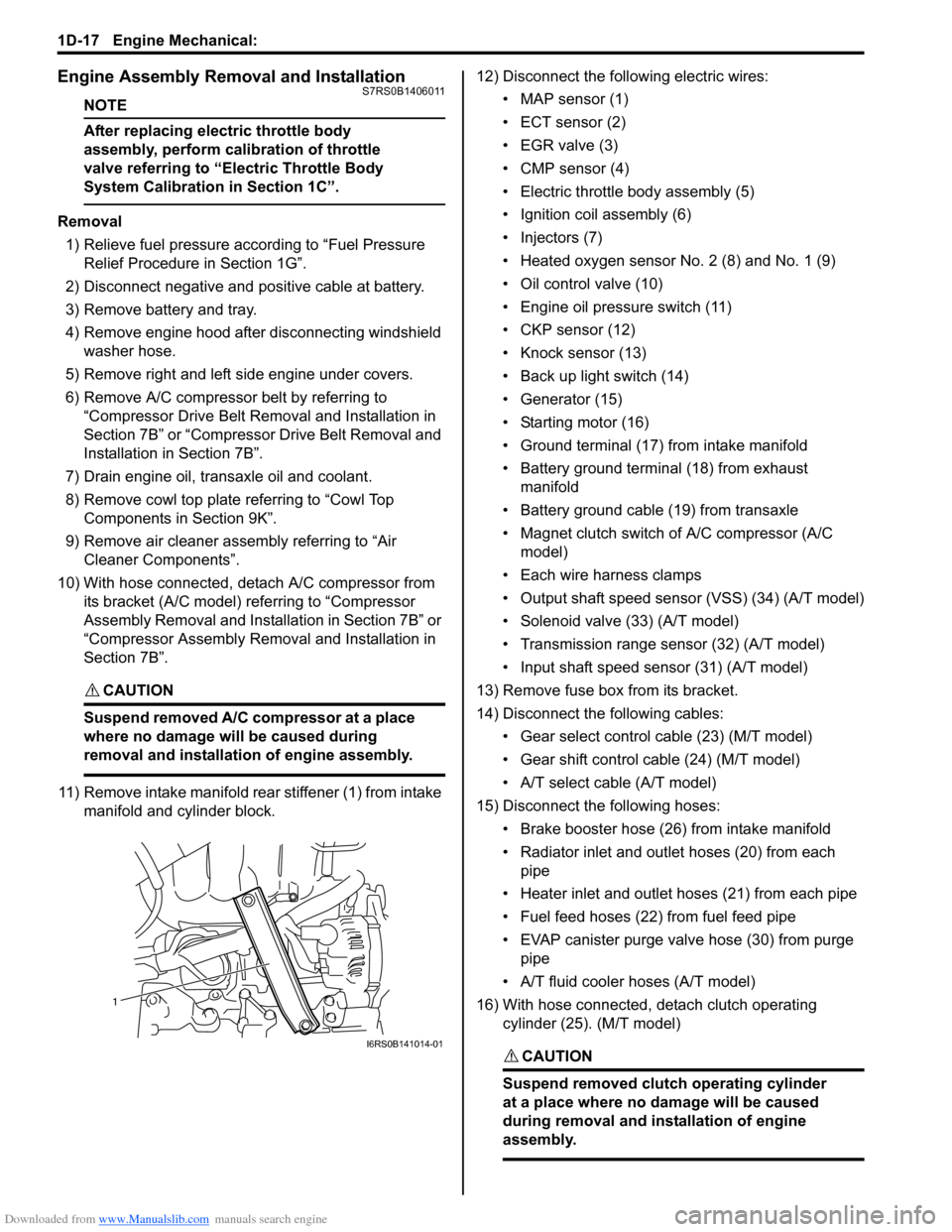
11) Remove intake manifold rear stiffener (1) from intake manifold and cylinder block. 12) Disconnect the following electric wires:
• MAP sensor (1)
• ECT sensor (2)
•EGR valve (3)
• CMP sensor (4)
• Electric throttle body assembly (5)
• Ignition coil assembly (6)
• Injectors (7)
• Heated oxygen sensor No. 2 (8) and No. 1 (9)
• Oil control valve (10)
• Engine oil pressure switch (11)
• CKP sensor (12)
• Knock sensor (13)
• Back up light switch (14)
• Generator (15)
• Starting motor (16)
• Ground terminal (17) from intake manifold
• Battery ground terminal (18) from exhaust manifold
• Battery ground cable (19) from transaxle
• Magnet clutch switch of A/C compressor (A/C model)
• Each wire harness clamps
• Output shaft speed sensor (VSS) (34) (A/T model)
• Solenoid valve (33) (A/T model)
• Transmission range sensor (32) (A/T model)
• Input shaft speed sensor (31) (A/T model)
13) Remove fuse box from its bracket.
14) Disconnect the following cables: • Gear select control cable (23) (M/T model)
• Gear shift control cable (24) (M/T model)
• A/T select cable (A/T model)
15) Disconnect the following hoses: • Brake booster hose (26) from intake manifold
• Radiator inlet and outlet hoses (20) from each pipe
• Heater inlet and outlet hoses (21) from each pipe
• Fuel feed hoses (22) from fuel feed pipe
• EVAP canister purge valve hose (30) from purge pipe
• A/T fluid cooler hoses (A/T model)
16) With hose connected, detach clutch operating cylinder (25). (M/T model)
CAUTION!
Suspend removed clutch operating cylinder
at a place where no damage will be caused
during removal and installation of engine
assembly.
1
I6RS0B141014-01
Page 303 of 1496

Downloaded from www.Manualslib.com manuals search engine Engine Mechanical: 1D-18
17) Disconnect right and left drive shaft joints from differential gear referring to “Front Drive Shaft
Assembly Removal and Installation in Section 3A”.
NOTE
For engine and transaxle removal, it is not
necessary to remove drive shafts from
steering knuckle.
18) Remove exhaust No.1, No.2 and center pipes referring to “Exhaust Pipe and Muffler Removal and
Installation in Section 1K”.
19) Support engine assemble by using chain hoist.
20) Remove suspension frame referring to “Front Suspension Frame, Stabiliz er Bar and/or Bushings
Removal and Installati on in Section 2B”.
21) Remove engine rear mounting from engine rear mounting No.1 bracket.
22) Support engine and transaxle with jack, and then remove chain hoist.
23) Remove engine left mounting bracket nuts (1) and engine right mounting nuts (2).
[A]: M/T model
[B]: A/T model
7
26
30
5
4
22
3
2
20
6
9
18
8
11
10
21 1
16
17
151213
[B]
23
24
14
25 19
34
33
32
32
31
[A]
I6RS0C140028-01
1
2
I4RS0A140008-01
Page 304 of 1496
Downloaded from www.Manualslib.com manuals search engine 1D-19 Engine Mechanical:
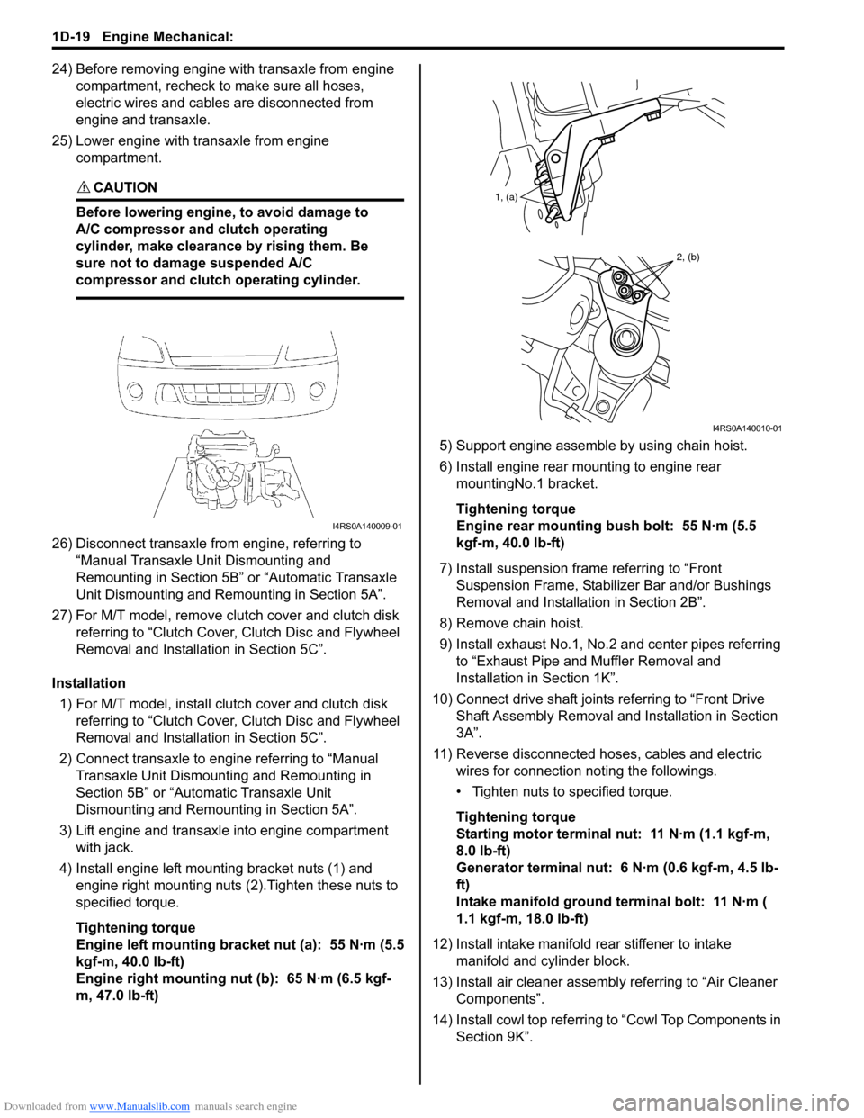
24) Before removing engine with transaxle from engine compartment, recheck to make sure all hoses,
electric wires and cables are disconnected from
engine and transaxle.
25) Lower engine with transaxle from engine compartment.
CAUTION!
Before lowering engine, to avoid damage to
A/C compressor and clutch operating
cylinder, make clearance by rising them. Be
sure not to damage suspended A/C
compressor and clutch operating cylinder.
26) Disconnect transaxle from engine, referring to “Manual Transaxle Unit Dismounting and
Remounting in Section 5B” or “Automatic Transaxle
Unit Dismounting and Re mounting in Section 5A”.
27) For M/T model, remove clutch cover and clutch disk referring to “Clutch Cover, Clutch Disc and Flywheel
Removal and Installa tion in Section 5C”.
Installation 1) For M/T model, install clutch cover and clutch disk referring to “Clutch Cover, Clutch Disc and Flywheel
Removal and Installa tion in Section 5C”.
2) Connect transaxle to engine referring to “Manual Transaxle Unit Dismounting and Remounting in
Section 5B” or “Automatic Transaxle Unit
Dismounting and Remounting in Section 5A”.
3) Lift engine and transaxle into engine compartment with jack.
4) Install engine left mounting bracket nuts (1) and engine right mounting nuts (2).Tighten these nuts to
specified torque.
Tightening torque
Engine left mounting bracket nut (a): 55 N·m (5.5
kgf-m, 40.0 lb-ft)
Engine right mounting nut (b): 65 N·m (6.5 kgf-
m, 47.0 lb-ft) 5) Support engine assemble by using chain hoist.
6) Install engine rear mounting to engine rear
mountingNo.1 bracket.
Tightening torque
Engine rear mounting bush bolt: 55 N·m (5.5
kgf-m, 40.0 lb-ft)
7) Install suspension frame referring to “Front Suspension Frame, Stabiliz er Bar and/or Bushings
Removal and Installati on in Section 2B”.
8) Remove chain hoist.
9) Install exhaust No.1, No.2 and center pipes referring to “Exhaust Pipe and Muffler Removal and
Installation in Section 1K”.
10) Connect drive shaft joints referring to “Front Drive Shaft Assembly Removal and Installation in Section
3A”.
11) Reverse disconnected hoses, cables and electric wires for connection noting the followings.
• Tighten nuts to specified torque.
Tightening torque
Starting motor terminal nut: 11 N·m (1.1 kgf-m,
8.0 lb-ft)
Generator terminal nut: 6 N·m (0.6 kgf-m, 4.5 lb-
ft)
Intake manifold ground terminal bolt: 11 N·m (
1.1 kgf-m, 18.0 lb-ft)
12) Install intake manifold rear stiffener to intake
manifold and cylinder block.
13) Install air cleaner assembly referring to “Air Cleaner Components”.
14) Install cowl top referring to “Cowl Top Components in
Section 9K”.
I4RS0A140009-01
1, (a)
2, (b)
I4RS0A140010-01
Page 364 of 1496

Downloaded from www.Manualslib.com manuals search engine 1F-1 Engine Cooling System:
Engine
Engine Cooling System
General Description
Cooling System DescriptionS7RS0B1601001
The cooling system consists of the radiator cap, radiator, coolant reservoir, hoses, water pump, cooling fan and
thermostat. The radiator is of tube-and-fin type.
Coolant DescriptionS7RS0B1601002
WARNING!
• Do not remove radiator cap to check engine coolant level; check coolant visually at the see-through coolant reservoir. Coolant should be added only to reservoir as necessary.
• As long as there is pressure in the cooling system, the temperature can be considerably higher than the boiling temperature of the solution in the radiator without causing the solution to boil. Removal
of the radiator cap while engine is hot and pressure is high will cause the solution to boil
instantaneously and possibly with explosive force, spewing the solution over engine, fenders and
person removing cap. If the solution contains flammable anti-freeze such as alcohol (not
recommended for use at any time), there is also the possibility of causing a serious fire.
• Check to make sure that engine coolant temperature is cold before removing any part of cooling system.
• Also be sure to disconnect negative cable from battery terminal before removing any part.
The coolant recovery system is standard. The coolant in the radiator expands with heat, and the coolant is overflowed
to the reservoir.
When the system cools down, the coolant is drawn back into the radiator.
The cooling system has be en filled with a quality coolant that is a 50/50 mixture of water and ethylene glycol
antifreeze.
This 50/50 mixture coolant solution provides freezing protection to –36 °C (–33 °F).
• Maintain cooling system freeze protection at –36 °C (–33 °F) to ensure protection against corrosion and loss of
coolant from boiling. This should be done even if freezing temperatures are not expected.
• Add ethylene glycol base coolant when coolant has to be added because of coolant loss or to provide added protection against freezing at temperature lower than –36 °C (–33 °F).
NOTE
• Alcohol or methanol base coolant or plain water alone should not be used in cooling system at any
time as damage to cooling system could occur.
• Coolant must be mixed with deminerated water or distilled water.
Anti-freeze proportioning table
For M/T model For A/T model
Freezing temperature °
C –36 –36
° F –33 –33
Anti-freeze / Anti-corrosion coolant concentration % 50 50
Ratio of compound to cooling water ltr. 3.10/3.10 3.05/3.05
US pt. 6.55/6.55 6.44/6.44
Imp pt. 5.46/5.46 5.37/5.37
Page 365 of 1496

Downloaded from www.Manualslib.com manuals search engine Engine Cooling System: 1F-2
Coolant capacity
For M/T model:• Engine, radiator and heater: 5.5 liters (11.62/9.68 US/lmp pt.)
• Reservoir: 0.7 liters (1.48/1.23 US/lmp pt.)
• Total: 6.2 liters (13.10/10.91 US/lmp pt.)
For A/T model: • Engine, radiator and heater: 5.4 liters (11.41/9.50 US/lmp pt.)
• Reservoir: 0.7 liters (1.48/1.23 US/lmp pt.)
• Total: 6.1 liters (12.89/10.74 US/lmp pt.)
Schematic and Routing Diagram
Coolant CirculationS7RS0B1602001
While the engine is warmed up (thermosta t closed), coolant circulates as follows.
11
10 3 7
4
9
8
6
5
2 12 1
13
I6RS0C160001-01
1. Radiator inlet hose
6. Water pump11. Heater core
2. Radiator outlet hose 7. Throttle body12. Radiator
3. Throttle body inlet hose 8. Engine13. Heat exchanger
4. Throttle body outlet hose 9. Heater core inlet hose
5. Thermostat 10. Heater core outlet hose
Page 382 of 1496

Downloaded from www.Manualslib.com manuals search engine 1G-7 Fuel System:
Fuel Pressure Relief ProcedureS7RS0B1706003
CAUTION!
This work must not be done when engine is
hot. If done so, it may cause adverse effect to
catalyst.
NOTE
If ECM detects DTC(s) after servicing, clear
DTC(s) referring to “DTC Clearance in
Section 1A”.
1) Make sure that engine is cold.
2) Shift transaxle gear shift lever in “Neutral” (shift select lever in “P” range for A/T model), set parking
brake and block drive wheels.
3) Remove relay / fuse box cover.
4) Disconnect fuel pump relay (1) from relay / fuse box (2).
5) Remove fuel filter cap in order to release fuel vapor pressure in fuel tank, and then reinstall it.
6) Start engine and run it until engine stops for lack of fuel. Repeat cranking engine 2 – 3 times for about 3
seconds each time in order to dissipate fuel pressure
in lines. Fuel connections are now safe for servicing.
7) After servicing, connect fuel pump relay (1) to relay / fuse box and install re lay / fuse box cover.
Fuel Leakage Check ProcedureS7RS0B1706004
After performing any service on fuel system, check to
make sure that there are no fuel leakages as follows.
1) Turn ON ignition switch for 3 seconds (to operate fuel pump) and then turn it OFF.
Repeat this (ON and OFF) 3 or 4 times and apply
fuel pressure to fuel line until fuel pressure is felt by
hand placed on fuel feed hose.
2) In this state, check to see that there are no fuel leakages from any part of fuel system.
Fuel Lines On-Vehicle InspectionS7RS0B1706005
CAUTION!
Due to the fact that fuel feed line (1) is under
high pressure, use special care when
servicing it.
Visually inspect fuel lines for evidence of fuel leakage,
hose crack and deterioration or damage.
Make sure all cl amps are secure.
Replace parts as needed.
Fuel Pipe Removal and InstallationS7RS0B1706006
WARNING!
Before starting the following procedure, be
sure to observe “Precautions on Fuel System
Service” in order to reduce the risk or fire
and personal injury.
Removal
1) Relieve fuel pressure in fuel feed line according to “Fuel Pressure Relief Procedure”.
2) Disconnect negative cable at battery.
3) Disconnect fuel pipe joint and fuel hose (3) from fuel pipe (2) at the front and rear of each fuel pipe
referring to “Fuel Hose Disconnecting and
Reconnecting”.
4) Mark the location of clamps (1) on fuel pipes (2), so that the clamps can be reinstalled to where they
were.
5) Remove pipes (2) with clamp (1) from vehicle.
6) Remove clamp (1) from pipes (2).
1
I4RS0A170004-01
1
I4RS0A170005-01
2
13
I4RS0A170020-01
Page 385 of 1496

Downloaded from www.Manualslib.com manuals search engine Fuel System: 1G-10
4) Install suitable vinyl tube onto injector nozzle to
prevent fuel from splashing out when injecting.
5) Put graduated cylinder under injector.
6) Operate fuel pump and apply fuel pressure to
injector as follows:
a) When using scan tool:
i) Connect scan tool to DLC with ignition switch OFF.
ii) Turn ignition switch ON, clear DTC and select “MISC TEST” mode on scan tool.
iii) Turn fuel pump ON by using scan tool.
Special tool
(A): SUZUKI scan tool
b) When not using scan tool: i) Remove fuel pump relay from connector.
ii) Connect two terminals of relay connector using service wire (1) as shown in figure.
CAUTION!
Check to make sure that connection is made
between correct terminals. Wrong
connection can cause damage to ECM, wire
harness, etc.
iii) Turn ignition switch ON. 7) Apply battery voltage to in
jector (1) for 15 seconds
and measure injected fuel volume with graduated
cylinder. Test each injector two or three times. If not
within specification, replace injector.
Injected fuel volume
43 – 47 cc/15 sec. (1.45/1.51 – 1.58/1.65 US/lmp
oz/15 sec.)
8) Check fuel leakage from injector nozzle. Do not operate injector for this check (but fuel pump should
be at work). If fuel leaks (1) more than the following
specifications, replace.
Fuel leakage
Less than 1 drop/min.
Fuel Filler Cap InspectionS7RS0B1706010
WARNING!
Before starting the following procedure, be
sure to observe “Precautions on Fuel System
Service” in order to reduce the risk or fire
and personal injury.
Remove cap (1), and che ck gasket for even filler neck
imprint, and deterioration or any damage. If gasket (2) is
in malcondition, replace cap.
NOTE
If cap requires replacement, only a cap with
the same features should be used. Failure to
use correct cap can result in fire and
personal injury.
(A)I4RS0A170021-01
1
I4RS0A170006-02
I2RH0B170013-01
I2RH01170008-01