2008 SUZUKI SWIFT Mode
[x] Cancel search: ModePage 994 of 1496
Downloaded from www.Manualslib.com manuals search engine 7B-46 Air Conditioning System: Automatic Type
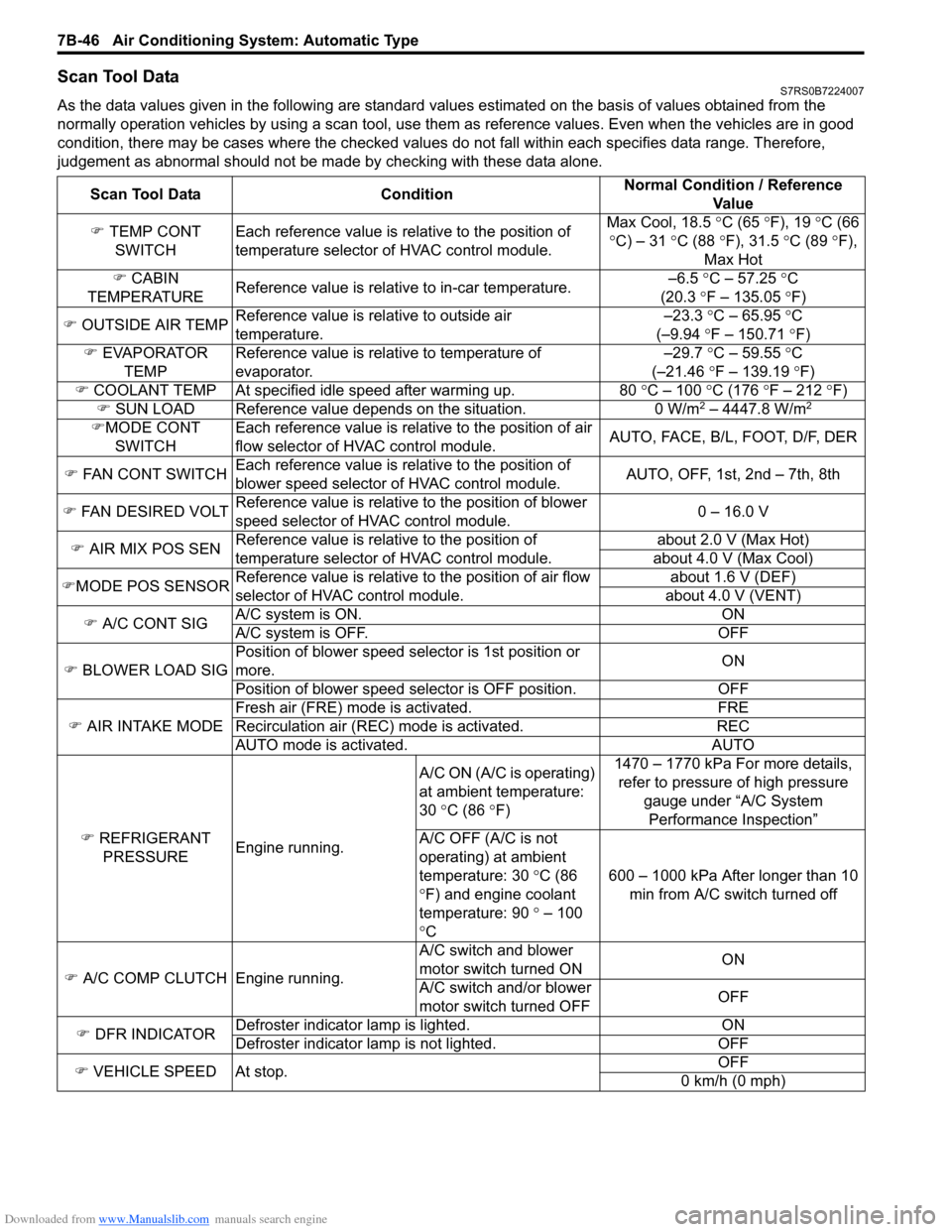
Scan Tool DataS7RS0B7224007
As the data values given in the following are standard values estimated on the basis of values obtained from the
normally operation vehicles by using a scan tool, use them as reference values. Even when the vehicles are in good
condition, there may be cases where the checked values do not fall within each specifies data range. Therefore,
judgement as abnormal should not be ma de by checking with these data alone.
Scan Tool Data Condition Normal Condition / Reference
Va l u e
) TEMP CONT
SWITCH Each reference value is relative to the position of
temperature selector of HVAC control module. Max Cool, 18.5
°C (65 ° F), 19 °C (66
° C) – 31 °C (88 °F), 31.5 °C (89 °F),
Max Hot
) CABIN
TEMPERATURE Reference value is relative to in-car temperature. –6.5
°C – 57.25 ° C
(20.3 °F – 135.05 °F)
) OUTSIDE AIR TEMP Reference value is relative to outside air
temperature. –23.3
°C – 65.95 °C
(–9.94 °F – 150.71 °F)
) EVAPORATOR
TEMP Reference value is relative to temperature of
evaporator. –29.7
°C – 59.55 °C
(–21.46 °F – 139.19 °F)
) COOLANT TEMP At specified id le speed after warming up. 80 °C – 100 °C (176 ° F – 212 ° F)
) SUN LOAD Reference value depends on the situation. 0 W/m
2 – 4447.8 W/m2
)MODE CONT
SWITCH Each reference value is relative to the position of air
flow selector of HVAC control module.
AUTO, FACE, B/L, FOOT, D/F, DER
) FAN CONT SWITCH Each reference value is relative to the position of
blower speed selector of HVAC control module. AUTO, OFF, 1st, 2nd – 7th, 8th
) FAN DESIRED VOLT Reference value is relative to the position of blower
speed selector of HVAC control module. 0 – 16.0 V
) AIR MIX POS SEN Reference value is relative to the position of
temperature selector of HVAC control module. about 2.0 V (Max Hot)
about 4.0 V (Max Cool)
) MODE POS SENSOR Reference value is relative to the position of air flow
selector of HVAC control module. about 1.6 V (DEF)
about 4.0 V (VENT)
) A/C CONT SIG A/C system is ON. ON
A/C system is OFF. OFF
) BLOWER LOAD SIG Position of blower speed selector is 1st position or
more.
ON
Position of blower speed selector is OFF position. OFF
) AIR INTAKE MODE Fresh air (FRE) mode is activated. FRE
Recirculation air (REC) mode is activated. REC
AUTO mode is activated. AUTO
) REFRIGERANT
PRESSURE Engine running. A/C ON (A/C is operating)
at ambient temperature:
30
°C (86 °F) 1470 – 1770 kPa For more details,
refer to pressure of high pressure
gauge under “A/C System Performance Inspection”
A/C OFF (A/C is not
operating) at ambient
temperature: 30 °C (86
° F) and engine coolant
temperature: 90 ° – 100
° C 600 – 1000 kPa After longer than 10
min from A/C switch turned off
) A/C COMP CLUTCH Engine running. A/C switch and blower
motor switch turned ON
ON
A/C switch and/or blower
motor switch turned OFF OFF
) DFR INDICATOR Defroster indicator
lamp is lighted. ON
Defroster indicator la mp is not lighted. OFF
) VEHICLE SPEED At stop. OFF
0 km/h (0 mph)
Page 995 of 1496
Downloaded from www.Manualslib.com manuals search engine Air Conditioning System: Automatic Type 7B-47
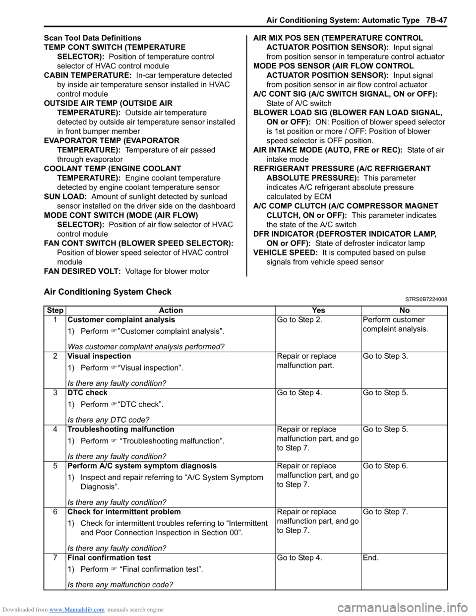
Scan Tool Data Definitions
TEMP CONT SWITCH (TEMPERATURE SELECTOR): Position of temperature control
selector of HVAC control module
CABIN TEMPERATURE: In-car temperature detected
by inside air temperature sensor installed in HVAC
control module
OUTSIDE AIR TEMP (OUTSIDE AIR TEMPERATURE): Outside air temperature
detected by outside air temperature sensor installed
in front bumper member
EVAPORATOR TEMP (EVAPORATOR TEMPERATURE): Temperature of air passed
through evaporator
COOLANT TEMP (ENGINE COOLANT TEMPERATURE): Engine coolant temperature
detected by engine coolant temperature sensor
SUN LOAD: Amount of sunlight detected by sunload
sensor installed on the driver side on the dashboard
MODE CONT SWITCH (MODE (AIR FLOW) SELECTOR): Position of air flow selector of HVAC
control module
FAN CONT SWITCH (BLOWER SPEED SELECTOR): Position of blower speed selector of HVAC control
module
FAN DESIRED VOLT: Voltage for blower motor AIR MIX POS SEN (TEMPERATURE CONTROL
ACTUATOR POSITI ON SENSOR): Input signal
from position sensor in temperature control actuator
MODE POS SENSOR (AIR FLOW CONTROL ACTUATOR POSITI ON SENSOR): Input signal
from position sensor in air flow control actuator
A/C CONT SIG (A/C SWITCH SIGNAL, ON or OFF): State of A/C switch
BLOWER LOAD SIG (BLO WER FAN LOAD SIGNAL,
ON or OFF): ON: Position of blower speed selector
is 1st position or more / OFF: Position of blower
speed selector is OFF position.
AIR INTAKE MODE (AUTO, FRE or REC): State of air
intake mode
REFRIGERANT PRESSURE (A/C REFRIGERANT ABSOLUTE PRESSURE): This parameter
indicates A/C refrigerant absolute pressure
calculated by ECM
A/C COMP CLUTCH (A/C COMPRESSOR MAGNET CLUTCH, ON or OFF): This parameter indicates
the state of the A/C switch
DFR INDICATOR (DEFROSTER INDICATOR LAMP, ON or OFF): State of defroster indicator lamp
VEHICLE SPEED: It is computed based on pulse
signals from vehicle speed sensor
Air Conditioning System CheckS7RS0B7224008
Step Action YesNo
1 Customer complaint analysis
1) Perform )”Customer complaint analysis”.
Was customer complaint analysis performed? Go to Step 2.
Perform customer
complaint analysis.
2 Visual inspection
1) Perform )“Visual inspection”.
Is there any faulty condition? Repair or replace
malfunction part.
Go to Step 3.
3 DTC check
1) Perform )“DTC check”.
Is there any DTC code? Go to Step 4.
Go to Step 5.
4 Troubleshooting malfunction
1) Perform ) “Troubleshooting malfunction”.
Is there any faulty condition? Repair or replace
malfunction part, and go
to Step 7.
Go to Step 5.
5 Perform A/C system symptom diagnosis
1) Inspect and repair referri ng to “A/C System Symptom
Diagnosis”.
Is there any faulty condition? Repair or replace
malfunction part, and go
to Step 7.
Go to Step 6.
6 Check for intermittent problem
1) Check for intermittent troubles referring to “Intermittent
and Poor Connection Inspection in Section 00”.
Is there any faulty condition? Repair or replace
malfunction part, and go
to Step 7.
Go to Step 7.
7 Final confirmation test
1) Perform ) “Final confirmation test”.
Is there any malfunction code? Go to Step 4.
End.
Page 1011 of 1496
Downloaded from www.Manualslib.com manuals search engine Air Conditioning System: Automatic Type 7B-63
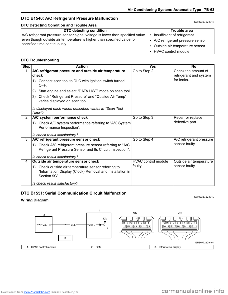
DTC B1546: A/C Refrigerant Pressure MalfunctionS7RS0B7224018
DTC Detecting Condition and Trouble Area
DTC Troubleshooting
DTC B1551: Serial Communication Circuit MalfunctionS7RS0B7224019
Wiring DiagramDTC detecting condition Trouble area
A/C refrigerant pressure sensor signal voltage is lower t han specified value
even though outside air temperature is higher than specified value for
specified time continuously. • Insufficient of refrigerant
• A/C refrigerant pressure sensor
• Outside air temperature sensor
• HVAC control module
Step
Action YesNo
1 A/C refrigerant pressure and outside air temperature
check
1) Connect scan tool to DLC with ignition switch turned
OFF.
2) Start engine and select “DATA LIST” mode on scan tool.
3) Check “Refrigerant Pressure” and “Outside Air Temp” varies displayed on scan tool.
Is displayed each va ries described varies in “Scan Tool
Data”? Go to Step 2.
Check the amount of
refrigerant and system
for leaks.
2 A/C system performance check
1) Check A/C system performance referring to “A/C System
Performance Inspection”.
Is check result satisfactory? Go to Step 3.
Repair or replace
defective part.
3 A/C refrigerant pressure sensor check
1) Check A/C refrigerant pressure sensor referring to “A/C
Refrigerant Pressure Sensor and Its Circuit Inspection”.
Is check result satisfactory? Go to Step 4.
A/C refrigerant pressure
sensor faulty.
4 Outside air temperature sensor check
1) Check outside air temperature sensor referring to
“Information Display (Clock) Removal and Installation in
Section 9C”.
Is check result satisfactory? HVAC control module
faulty.
Outside air temperature
sensor faulty.
YEL17812910
65 431516 14 13 12 11
G52
789101920121112
65 431718 16 15 14 13
G51
G51-7
12V
2
3
G37-11
I5RS0A722016-01
1. HVAC control module 2. BCM3. Information display
Page 1013 of 1496
Downloaded from www.Manualslib.com manuals search engine Air Conditioning System: Automatic Type 7B-65
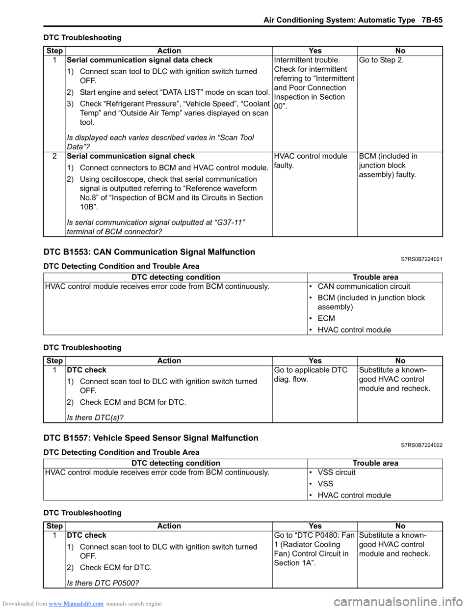
DTC Troubleshooting
DTC B1553: CAN Communication Signal MalfunctionS7RS0B7224021
DTC Detecting Condition and Trouble Area
DTC Troubleshooting
DTC B1557: Vehicle Speed Sensor Signal MalfunctionS7RS0B7224022
DTC Detecting Condition and Trouble Area
DTC TroubleshootingStep Action Yes No
1 Serial communication signal data check
1) Connect scan tool to DLC with ignition switch turned
OFF.
2) Start engine and select “DATA LIST” mode on scan tool.
3) Check “Refrigerant Pressure”, “Vehicle Speed”, “Coolant Temp” and “Outside Air Temp” varies displayed on scan
tool.
Is displayed each va ries described varies in “Scan Tool
Data”? Intermittent trouble.
Check for intermittent
referring to “Intermittent
and Poor Connection
Inspection in Section
00”.
Go to Step 2.
2 Serial communication signal check
1) Connect connectors to BCM and HVAC control module.
2) Using oscilloscope, check that serial communication
signal is outputted referring to “Reference waveform
No.8” of “Inspection of BCM and its Circuits in Section
10B”.
Is serial communication signal outputted at “G37-11”
terminal of BCM connector? HVAC control module
faulty.
BCM (included in
junction block
assembly) faulty.
DTC detecting condition
Trouble area
HVAC control module receives error code fr om BCM continuously.• CAN communication circuit
• BCM (included in junction block assembly)
•ECM
• HVAC control module
Step Action YesNo
1 DTC check
1) Connect scan tool to DLC with ignition switch turned
OFF.
2) Check ECM and BCM for DTC.
Is there DTC(s)? Go to applicable DTC
diag. flow.
Substitute a known-
good HVAC control
module and recheck.
DTC detecting condition
Trouble area
HVAC control module receives error code from BCM continuously. • VSS circuit
• VSS
• HVAC control module
Step Action YesNo
1 DTC check
1) Connect scan tool to DLC with ignition switch turned
OFF.
2) Check ECM for DTC.
Is there DTC P0500? Go to “DTC P0480: Fan
1 (Radiator Cooling
Fan) Control Circuit in
Section 1A”.
Substitute a known-
good HVAC control
module and recheck.
Page 1016 of 1496
Downloaded from www.Manualslib.com manuals search engine 7B-68 Air Conditioning System: Automatic Type
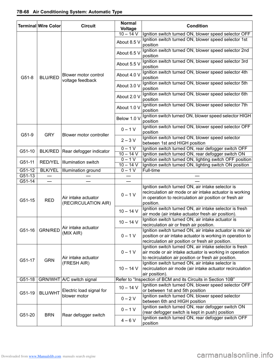
G51-8 BLU/REDBlower motor control
voltage feedback 10 – 14 V Ignition switch turned ON, blower speed selector OFF
About 8.5 V Ignition switch turned ON, blower speed selector 1st
position
About 6.5 V Ignition switch turned ON, blower speed selector 2nd
position
About 5.5 V Ignition switch turned ON, blower speed selector 3rd
position
About 4.0 V Ignition switch turned ON, blower speed selector 4th
position
About 3.0 V Ignition switch turned ON, blower speed selector 5th
position
About 2.0 V Ignition switch turned ON, blower speed selector 6th
position
About 1.0 V Ignition switch turned ON, blower speed selector 7th
position
Below 1.0 V Ignition switch turned ON, blower speed selector HIGH
position
G51-9 GRY Blower motor controller 0 – 1 V
Ignition switch turned ON, blower speed selector OFF
position
2 – 3 V Ignition switch turned ON, blower speed selector
between 1st and HIGH position
G51-10 BLK/RED Rear defogger indicator 0 – 1 V Ignition switch turned ON, rear defogger switch OFF
10 – 14 V Ignition switch turned ON, rear defogger switch ON
G51-11 RED/YEL Illumination switch 0 – 1 V Ignition switch turned ON, lighting switch OFF position
10 – 14 V Ignition switch turned ON, lighting switch ON position
G51-12 BLK/YEL Illumination ground 0 – 1 V Full-time
G51-13 — — — —
G51-14 — — — —
G51-15 RED Air intake actuator
(RECIRCULATION AIR) 0 – 1 VIgnition switch turned ON, air intake selector is
recirculation air mode or air intake actuator is working
in operation to recirculation air position or fresh air
position.
10 – 14 V Ignition switch turned ON, ai
r intake selector is fresh
air mode (air intake actuator fresh air position).
G51-16 GRN/RED Air intake actuator
(MIX AIR) 10 – 14 V
Ignition switch turned ON, air intake actuator is
recirculation air or fresh air position.
0 – 1 V Ignition switch turned ON, air intake actuator is mix air
position or air intake actuator is working in operation to
recirculation air position or fresh air position.
G51-17 GRN Air intake actuator
(FRESH AIR) 0 – 1 V
Ignition switch turned ON, ai
r intake selector is fresh
air mode or air intake actuator is working in operation
to recirculation air position or fresh air position.
10 – 14 V Ignition switch turned ON, air intake selector is
recirculation air mode (air intake actuator recirculation
air position).
G51-18 GRN/WHT A/C switch signal Refer to “Inspe ction of BCM and its Circuits in Section 10B”
G51-19 BLU/WHT Electric load signal for
blower motor 10 – 14 V
Ignition switch turned ON, blower speed selector OFF
or between 1st and 5th position
0 – 2 V Ignition switch turned ON, blower speed selector
between 6th and HIGH position
G51-20 BRN Rear defogger switch 0 – 1 V
Ignition switch turned ON, rear defogger switch ON
(rear defogger switch is kept in push) position
4 – 6 V Ignition switch turned ON, rear defogger switch OFF
position
Terminal Wire Color Circuit
Normal
Vo l ta g e Condition
Page 1023 of 1496
Downloaded from www.Manualslib.com manuals search engine Air Conditioning System: Automatic Type 7B-75
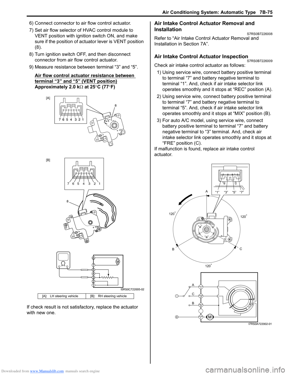
6) Connect connector to air flow control actuator.
7) Set air flow selector of HVAC control module to VENT position with ignition switch ON, and make
sure if the position of act uator lever is VENT position
(8).
8) Turn ignition switch OFF, and then disconnect connector from air flow control actuator.
9) Measure resistance between terminal “3” and “5”.
Air flow control actuator resistance between
terminal “3” and “5” (VENT position)
Approximately 2.0 k Ω at 25 °C (77 °F)
If check result is not satisfactory, replace the actuator
with new one.
Air Intake Control Actuator Removal and
Installation
S7RS0B7226008
Refer to “Air Intake Control Actuator Removal and
Installation in Section 7A”.
Air Intake Control Actuator InspectionS7RS0B7226009
Check air intake contro l actuator as follows:
1) Using service wire, connect battery positive terminal
to terminal “7” and battery negative terminal to
terminal “1”. And, check if air intake selector link
operates smoothly and it stops at “REC” position (A).
2) Using service wire, connect battery positive terminal
to terminal “7” and battery negative terminal to
terminal “5”. And, check if air intake selector link
operates smoothly and it stops at “MIX” position (B).
3) For auto A/C model, using service wire, connect battery positive terminal to terminal “7” and battery
negative terminal to “3” terminal. And, check air
intake selector link operates smoothly and it stops at
“FRE” position (C).
If malfunction is found, replace air intake control
actuator.
[A]: LH steering vehicl e [B]: RH steering vehicle
[A]
[B]
8
8765 4 3 21
I5RS0C722005-02
A
C
B“a”
“a”“a”
-
+
A
C
B “1” “3” “5” “7”
“1”
“3”
“5”
“7”
120
°
120° 120
°
I7RS0A722002-01
Page 1168 of 1496
Downloaded from www.Manualslib.com manuals search engine 9-ii Table of Contents
List of Connectors ........................................... 9A-103
C Connector .................................................... 9A-103
D Connector (M16A engine) ........................... 9A-104
E Connector .................................................... 9A-104
G Connector .................................................... 9A-106
J Connector ..................................................... 9A-108
K Connector .................................................... 9A-109
L Connector..................................................... 9A-109
M Connector (SPORT model) ......................... 9A-111
O Connector .................................................... 9A-111
R Connector .................................................... 9A-111
Lighting Systems .................................... 9B-1
Component Location ........... ................................9B-1
Lighting System Component s Location............... 9B-1
Interior Light System Location............................. 9B-2
Diagnostic Information and Procedures ............ 9B-2 Headlight Symptom Diagnosis ............................ 9B-2
Headlight Leveling System Symptom Diagnosis (If Equipped) ..................................... 9B-2
Turn Signal and Hazard Warning Light Symptom Diagnosis .......................................... 9B-3
Clearance, Tail and License Plate Light Symptom Diagnosis .......................................... 9B-3
Back-Up Light Symptom Diagnosis..................... 9B-4
Brake Light Symptom Diagnosis ......................... 9B-4
Front Fog Light Symptom Diagnosis (If Equipped) .......................................................... 9B-4
Interior Light Symptom Diagnosis ....................... 9B-5
Repair Instructions ..............................................9B-5 Headlight Housing Removal and Installation ...... 9B-5
Headlight Bulb Replacemen t............................... 9B-6
Headlight Aiming Adjustment with Screen .......... 9B-6
Headlight Switch (in Lighting Switch) Removal and Installation ................................... 9B-8
Headlight Switch (in Lighting Switch) Inspection .......................................................... 9B-8
Hazard Warning Switch Removal and Installation ......................................................... 9B-8
Hazard Warning Switch Inspection ..................... 9B-9
Brake Light Switch Inspection ............................. 9B-9
Turn Signal Light Switch (in Lighting Switch) Removal and Installation ................................... 9B-9
Turn Signal Light Switch (in Lighting Switch) Inspection .......................................................... 9B-9
Turn Signal and Hazard Warning Relay Removal and Installation ................................... 9B-9
Turn Signal and Hazard Warning Relay Inspection ........................................................ 9B-10
License Light Removal and Installation............. 9B-10
Front Fog Light Removal and Installation (If Equipped) ........................................................ 9B-11
Front Fog Light Bulb Replacement (If Equipped) ........................................................ 9B-11
Front Fog Light Switch Inspection (If Equipped) ........................................................ 9B-11
Front Fog Light Relay Inspection (If Equipped) ........................................................ 9B-11
Front Fog Light Aiming Adjustment with Screen (If Equipped) ....................................... 9B-12 Headlight Leveling Switch Inspection (If
Equipped) ........................................................ 9B-13
Headlight Leveling Actuator Inspection (If Equipped) ........................................................ 9B-13
Instrumentation / Driver Info. / Horn ...... 9C-1
Precautions ...........................................................9C-1 Precautions in Diagnosing Troubles for Combination Meter ............................................9C-1
General Description .............................................9C-1 CAN Communication System Description...........9C-1
Auto Volume Co ntrol System Description (If
Equipped) ..........................................................9C-3
Schematic and Routing Diagram ........................9C-4 Combination Meter Circuit Diagram ....................9C-4
Component Location ............ ...............................9C-6
Audio System Component Location ....................9C-6
Diagnostic Information and Procedures ............9C-6 Speedometer and VSS Symp tom Diagnosis ......9C-6
Tachometer Symptom Diagnosis ........................9C-6
Engine Coolant Temperature (ECT) Meter Symptom Diagnosis ..........................................9C-7
Fuel Meter Symptom Diagnosis ..........................9C-7
Low Fuel Warning Light Symptom Diagnosis .....9C-7
Oil Pressure Warning Light Symptom Diagnosis ..........................................................9C-8
Brake and Parking Brake Warning Light Symptom Diagnosis ..........................................9C-8
Seat Belt Reminder Light Symptom Diagnosis (If Equipped)......................................................9C-8
A/T Shift Position Indicator Symptom Diagnosis (A/T Model).......................................9C-9
Charge Warning Light Sy mptom Diagnosis ........9C-9
Main Beam (High Beam) Indicator Symptom Diagnosis ..........................................................9C-9
Warning Buzzer Circuit Sy mptom Diagnosis ....9C-10
Cigarette Lighter Symptom Diagnosis (If Equipped) ........................................................9C-10
Horn Symptom Diagnosis .................................9C-10
Information Display Symptom Diagnosis (If Equipped) ........................................................9C-11
Clock Symptom Diagnosis (If Equipped)...........9C-12
Audio System Symptom Diagnosis (If Equipped) ........................................................9C-12
Remote Audio Control Switch Symptom Diagnosis (If Equipped) ...................................9C-13
Navigation Symptom Diagnosis (If Equipped)...9C-14
Repair Instructions ............ ................................9C-14
Ignition Switch Removal and Installation...........9C-14
Ignition Switch Inspection..................................9C-14
Combination Meter Removal and Installation ...9C-15
Fuel Level Sensor Removal and Installation .....9C-15
Fuel Level Sensor Inspection ............................9C-15
Oil Pressure Switch Remova l and Installation ..9C-15
Oil Pressure Switch Inspec tion .........................9C-16
Engine Coolant Temperature (ECT) Sensor Inspection ........................................................9C-16
Brake Fluid Level Switch Inspection .................9C-16
Parking Brake Switch Inspec tion.......................9C-16
Page 1194 of 1496
Downloaded from www.Manualslib.com manuals search engine 9A-23 Wiring Systems:
J: Rear door wire
K: Roof wire
FloorS7RS0B910A005
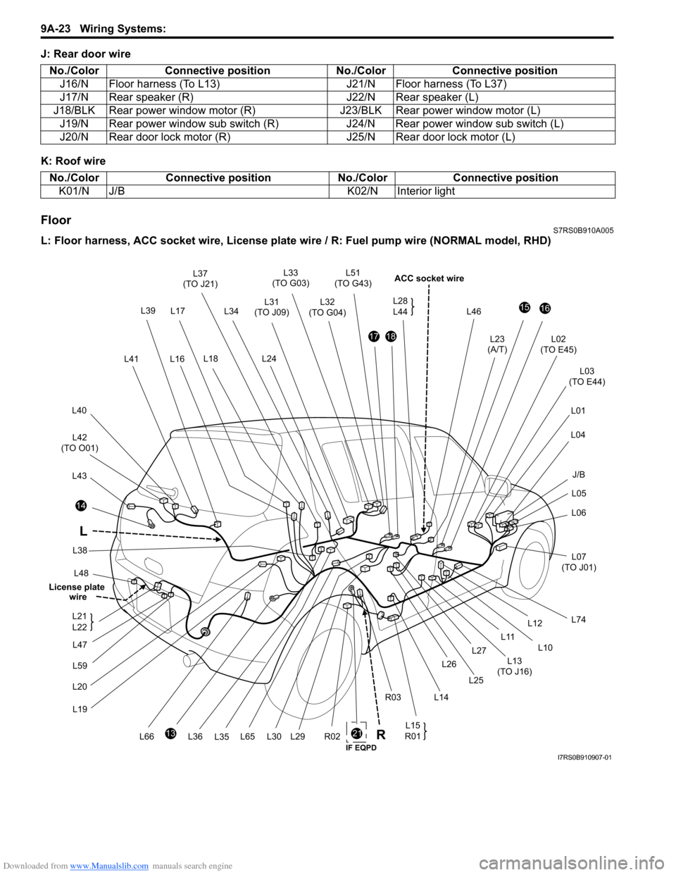
L: Floor harness, ACC socket wire, License plate wire / R: Fuel pum p wire (NORMAL model, RHD)
No./Color
Connective position No./ColorConnective position
J16/N Floor harness (To L13) J21/N Floor harness (To L37)
J17/N Rear speaker (R) J22/N Rear speaker (L)
J18/BLK Rear power window motor (R) J23/BLK Rear power window motor (L)
J19/N Rear power window sub switch (R) J24/N Rear power window sub switch (L)
J20/N Rear door lock motor (R) J25/N Rear door lock motor (L)
No./ColorConnective position No./Color Connective position
K01/N J/B K02/N Interior light
21
L48
14
L43
L42
(TO O01)
L40
L41
L33
(TO G03)
L32
(TO G04)
L46
ACC socket wire
L02
(TO E45)
L03
(TO E44)
L01
L04
L05
L06
L07
(TO J01)
L74
1516
L23
(A/T)1718
L31
(TO J09)
L24
13
L20L19
R02L65L66 L15
R01
L12
L10
L11
L13
(TO J16)
L14
R03 L26
L25
L27
L30L29
L17
L18 L51
(TO G43)
L36 L35
L37
(TO J21)
L34
L38
L16 L28
L44
L
L39
J/B
R
L47
L59
L21
L22
License plate
wire
IF EQPDI7RS0B910907-01