2008 SUZUKI SWIFT meter
[x] Cancel search: meterPage 316 of 1496
Downloaded from www.Manualslib.com manuals search engine 1D-31 Engine Mechanical:
7) Install camshaft housing.
8) Tighten camshaft housing bolts as follows.a) Apply engine oil to camshaft housing bolts.
b) Tighten camshaft housing bolts by hand.
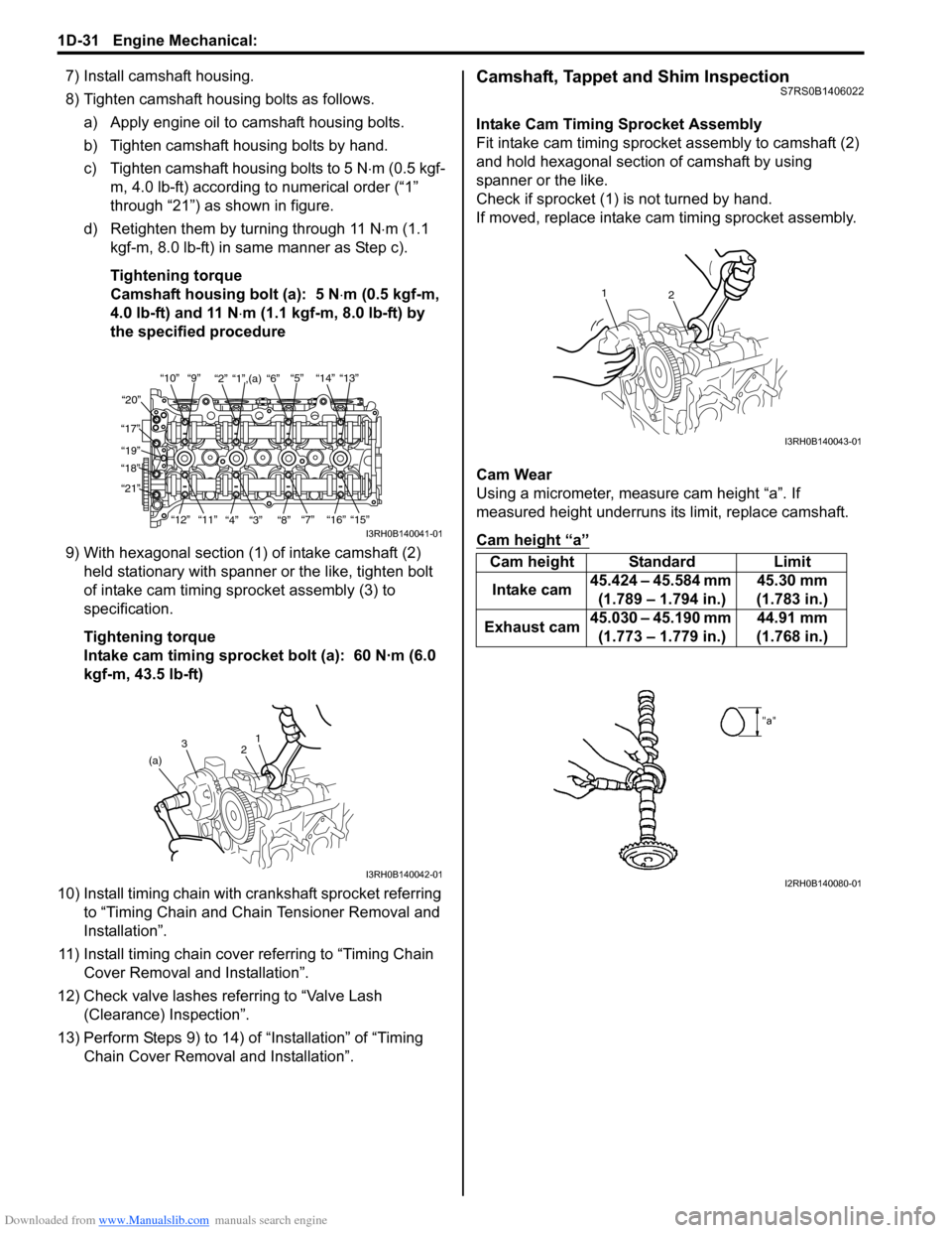
c) Tighten camshaft housing bolts to 5 N ⋅m (0.5 kgf-
m, 4.0 lb-ft) according to numerical order (“1”
through “21”) as shown in figure.
d) Retighten them by turning through 11 N⋅ m (1.1
kgf-m, 8.0 lb-ft) in same manner as Step c).
Tightening torque
Camshaft housing bolt (a): 5 N ⋅m (0.5 kgf-m,
4.0 lb-ft) and 11 N ⋅m (1.1 kgf-m, 8.0 lb-ft) by
the specified procedure
9) With hexagonal section (1) of intake camshaft (2) held stationary with spanner or the like, tighten bolt
of intake cam timing sp rocket assembly (3) to
specification.
Tightening torque
Intake cam timing sprocket bolt (a): 60 N·m (6.0
kgf-m, 43.5 lb-ft)
10) Install timing chain with cr ankshaft sprocket referring
to “Timing Chain and Chain Tensioner Removal and
Installation”.
11) Install timing chain cover referring to “Timing Chain Cover Removal and Installation”.
12) Check valve lashes referring to “Valve Lash (Clearance) Inspection”.
13) Perform Steps 9) to 14) of “Installation” of “Timing Chain Cover Removal and Installation”.Camshaft, Tappet and Shim InspectionS7RS0B1406022
Intake Cam Timing Sprocket Assembly
Fit intake cam timing sprocket assembly to camshaft (2)
and hold hexagonal section of camshaft by using
spanner or the like.
Check if sprocket (1) is not turned by hand.
If moved, replace intake ca m timing sprocket assembly.
Cam Wear
Using a micrometer, measure cam height “a”. If
measured height underruns its limit, replace camshaft.
Cam height “a”
“10”“9” “2” “1”,(a) “6” “5” “14” “13”
“20”
“17” “19”
“18”
“21”
“12”“11”
“4” “3” “8” “7” “16” “15”
I3RH0B140041-01
1
2
3
(a)
I3RH0B140042-01
Cam height Standard Limit
Intake cam 45.424 – 45.584 mm
(1.789 – 1.794 in.) 45.30 mm
(1.783 in.)
Exhaust cam 45.030 – 45.190 mm
(1.773 – 1.779 in.) 44.91 mm
(1.768 in.)
2
1
I3RH0B140043-01
I2RH0B140080-01
Page 318 of 1496
Downloaded from www.Manualslib.com manuals search engine 1D-33 Engine Mechanical:
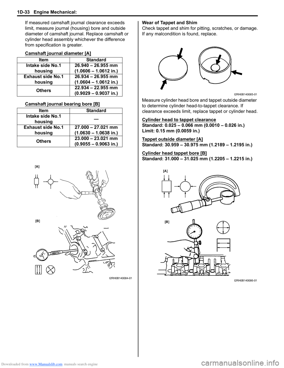
If measured camshaft journal clearance exceeds
limit, measure journal (housing) bore and outside
diameter of camshaft journal. Replace camshaft or
cylinder head assembly whichever the difference
from specification is greater.
Camshaft journal diameter [A]
Camshaft journal bearing bore [B]
Wear of Tappet and Shim
Check tappet and shim for pitting, scratches, or damage.
If any malcondition is found, replace.
Measure cylinder head bore and tappet outside diameter
to determine cylinder head-to-tappet clearance. If
clearance exceeds limit, replace tappet or cylinder head.
Cylinder head to tappet clearance
Standard: 0.025 – 0.066 mm (0.0010 – 0.026 in.)
Limit: 0.15 mm (0.0059 in.)
Tappet outside diameter [A]
Standard: 30.959 – 30.975 mm (1.2189 – 1.2195 in.)
Cylinder head tappet bore [B]
Standard: 31.000 – 31.025 mm (1.2205 – 1.2215 in.)
Item Standard
Intake side No.1 housing 26.940 – 26.955 mm
(1.0606 – 1.0612 in.)
Exhaust side No.1 housing 26.934 – 26.955 mm
(1.0604 – 1.0612 in.)
Others 22.934 – 22.955 mm
(0.9029 – 0.9037 in.)
Item Standard
Intake side No.1 housing —
Exhaust side No.1 housing 27.000 – 27.021 mm
(1.0630 – 1.0638 in.)
Others 23.000 – 23.021 mm
(0.9055 – 0.9063 in.)
I2RH0B140084-01
I2RH0B140085-01
I2RH0B140086-01
Page 321 of 1496
Downloaded from www.Manualslib.com manuals search engine Engine Mechanical: 1D-36
5) Install cylinder head to cylinder block.Apply engine oil to new cylinder head bolts and
tighten them gradually as follows.
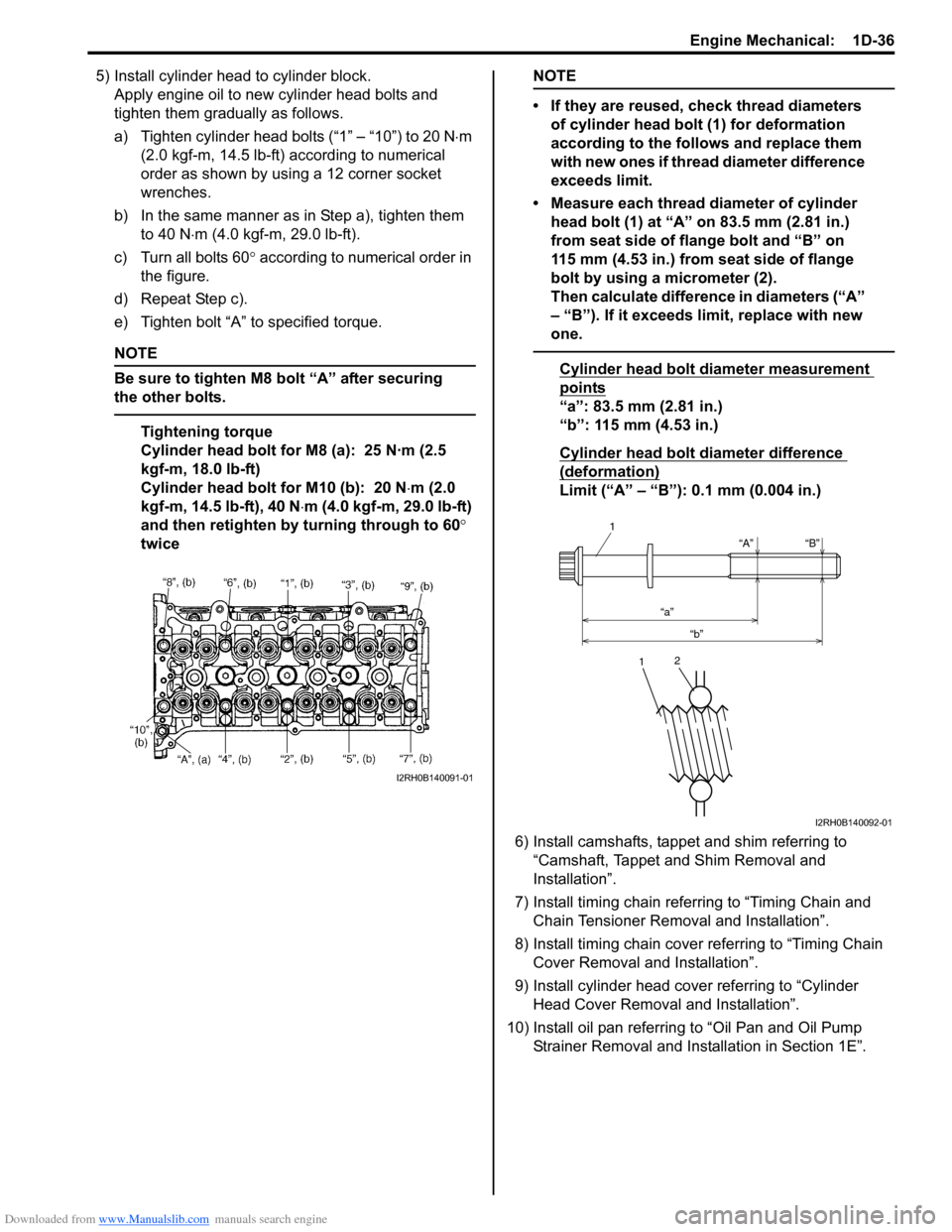
a) Tighten cylinder head bolts (“1” – “10”) to 20 N ⋅m
(2.0 kgf-m, 14.5 lb-ft) according to numerical
order as shown by using a 12 corner socket
wrenches.
b) In the same manner as in Step a), tighten them to 40 N ⋅m (4.0 kgf-m, 29.0 lb-ft).
c) Turn all bolts 60 ° according to numerical order in
the figure.
d) Repeat Step c).
e) Tighten bolt “A” to specified torque.
NOTE
Be sure to tighten M8 bolt “A” after securing
the other bolts.
Tightening torque
Cylinder head bolt for M8 (a): 25 N·m (2.5
kgf-m, 18.0 lb-ft)
Cylinder head bolt for M10 (b): 20 N ⋅m (2.0
kgf-m, 14.5 lb-ft), 40 N ⋅m (4.0 kgf-m, 29.0 lb-ft)
and then retighten by turning through to 60 °
twice
NOTE
• If they are reused, check thread diameters of cylinder head bolt (1) for deformation
according to the follows and replace them
with new ones if thread diameter difference
exceeds limit.
• Measure each thread diameter of cylinder head bolt (1) at “A” on 83.5 mm (2.81 in.)
from seat side of flange bolt and “B” on
115 mm (4.53 in.) from seat side of flange
bolt by using a micrometer (2).
Then calculate difference in diameters (“A”
– “B”). If it exceeds limit, replace with new
one.
Cylinder head bolt diameter measurement
points
“a”: 83.5 mm (2.81 in.)
“b”: 115 mm (4.53 in.)
Cylinder head bolt diameter difference
(deformation)
Limit (“A” – “B”): 0.1 mm (0.004 in.)
6) Install camshafts, tappet and shim referring to “Camshaft, Tappet and Shim Removal and
Installation”.
7) Install timing chain referring to “Timing Chain and Chain Tensioner Remova l and Installation”.
8) Install timing chain cover referring to “Timing Chain Cover Removal and Installation”.
9) Install cylinder head cover referring to “Cylinder Head Cover Removal and Installation”.
10) Install oil pan referring to “Oil Pan and Oil Pump
Strainer Removal and Inst allation in Section 1E”.
I2RH0B140091-01
“A”
“a” “b” “B”
1
1
2
I2RH0B140092-01
Page 325 of 1496
Downloaded from www.Manualslib.com manuals search engine Engine Mechanical: 1D-40
Valves and Valve Guides InspectionS7RS0B1406026
Valve Guide
Valve stem-to-guide clearance
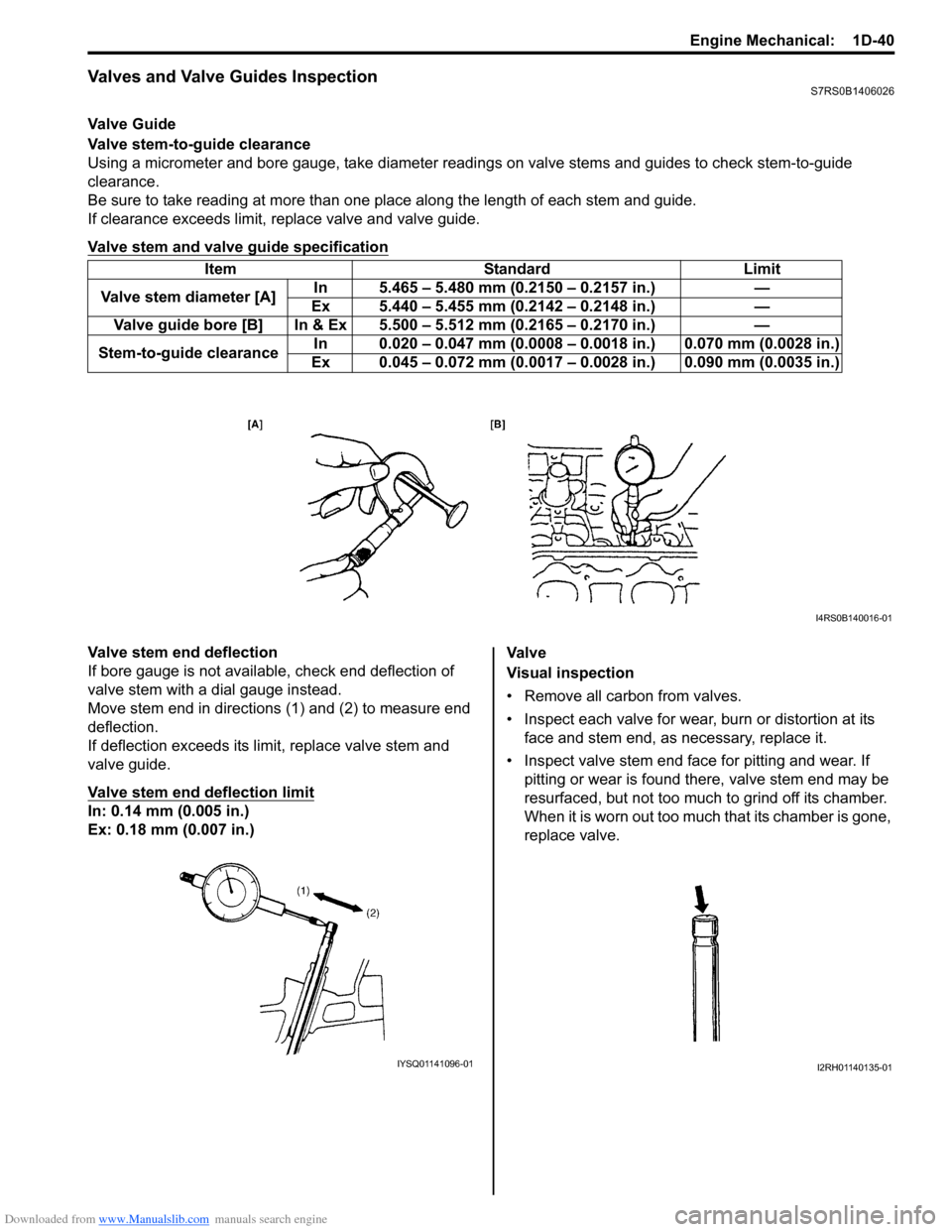
Using a micrometer and bore gauge, take diameter readings on valve stems and guides to check stem-to-guide
clearance.
Be sure to take reading at more than one place along the length of each stem and guide.
If clearance exceeds limit, replace valve and valve guide.
Valve stem and valve guide specification
Valve stem end deflection
If bore gauge is not available, check end deflection of
valve stem with a dial gauge instead.
Move stem end in directions (1) and (2) to measure end
deflection.
If deflection exceeds its limit, replace valve stem and
valve guide.
Valve stem end deflection limit
In: 0.14 mm (0.005 in.)
Ex: 0.18 mm (0.007 in.) Va l v e
Visual inspection
• Remove all carbon from valves.
• Inspect each valve for wear, burn or distortion at its
face and stem end, as necessary, replace it.
• Inspect valve stem end face for pitting and wear. If pitting or wear is found there, valve stem end may be
resurfaced, but not too much to grind off its chamber.
When it is worn out too much that its chamber is gone,
replace valve.
Item Standard Limit
Valve stem diameter [A] In 5.465 – 5.480 mm (0.2150 – 0.2157 in.) —
Ex 5.440 – 5.455 mm (0.2142 – 0.2148 in.) —
Valve guide bore [B] In & Ex 5.500 – 5.512 mm (0.2165 – 0.2170 in.) —
Stem-to-guide clearance In 0.020 – 0.047 mm (0.0008 – 0.
0018 in.) 0.070 mm (0.0028 in.)
Ex 0.045 – 0.072 mm (0.0017 – 0. 0028 in.) 0.090 mm (0.0035 in.)
I4RS0B140016-01
IYSQ01141096-01I2RH01140135-01
Page 329 of 1496
Downloaded from www.Manualslib.com manuals search engine Engine Mechanical: 1D-44
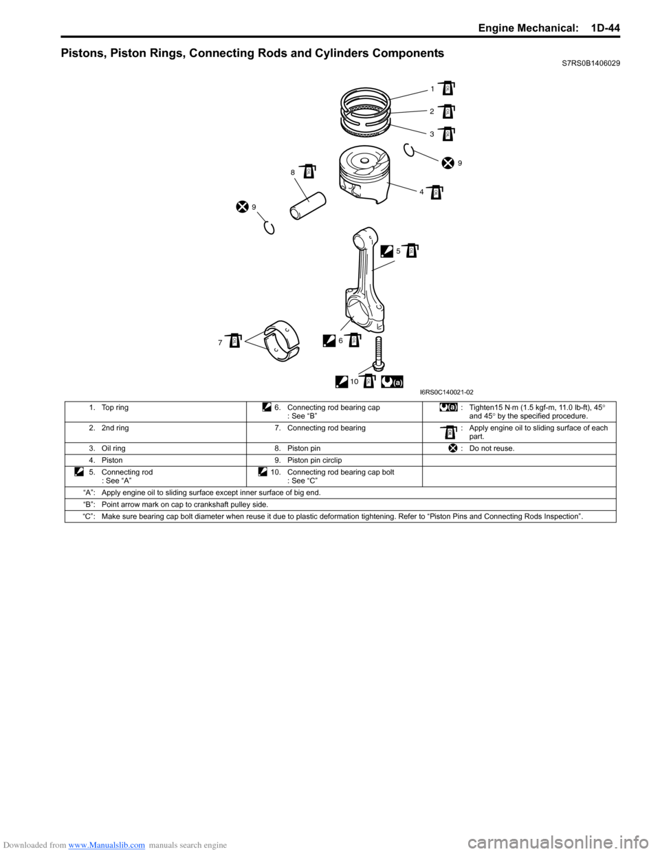
Pistons, Piston Rings, Connecting Rods and Cylinders ComponentsS7RS0B1406029
1. Top ring 6. Connecting rod bearing cap : See “B”: Tighten15 N
⋅m (1.5 kgf-m, 11.0 lb-ft), 45 °
and 45 ° by the specified procedure.
2. 2nd ring 7. Connecting rod bearing : Apply engine oil to sliding surface of each
part.
3. Oil ring 8. Piston pin : Do not reuse.
4. Piston 9. Piston pin circlip
5. Connecting rod : See “A” 10. Connecting rod bearing cap bolt
: See “C”
“A”: Apply engine oil to sliding surface except inner surface of big end.
“B”: Point arrow mark on cap to crankshaft pulley side.
“C”: Make sure bearing cap bolt diameter when reuse it due to plastic deformation tightening. Refer to “Piston Pins and Connecti ng Rods Inspection”.
(a)1
2
3
9
4
5
6 10
7 8
9
OIL
OIL
OIL
OIL
OIL
OIL
OIL
OIL
OIL
I6RS0C140021-02
Page 332 of 1496
Downloaded from www.Manualslib.com manuals search engine 1D-47 Engine Mechanical:
Cylinders, Pistons and Piston Rings InspectionS7RS0B1406032
Cylinder
Visual inspection
Inspect cylinder walls for scratches, roughness or ridges
which indicate excessive wear. If cylinder bore is very
rough or deeply scratched, or ridged, rebore cylinder and
use over size piston.
Cylinder bore diameter, taper and out-of-round
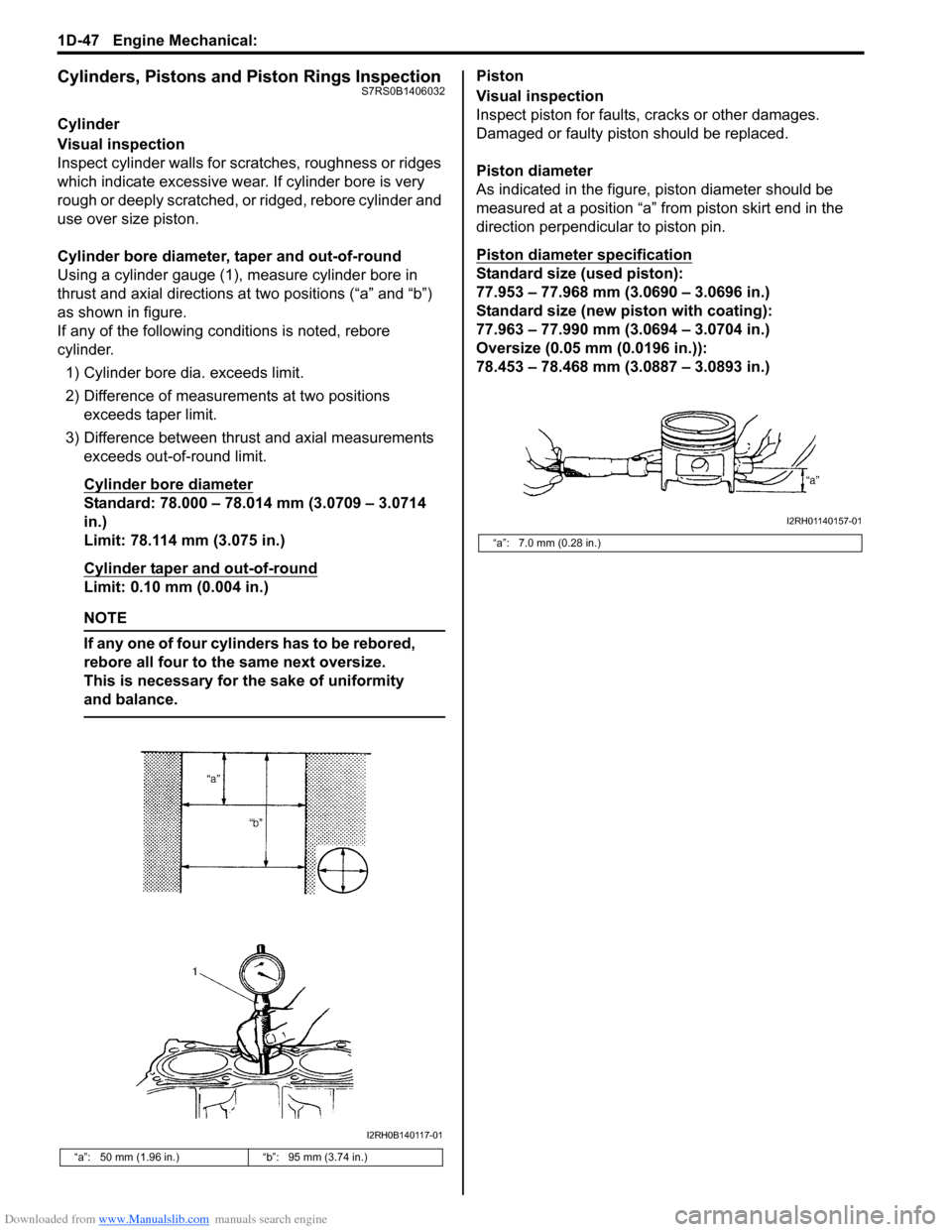
Using a cylinder gauge (1), measure cylinder bore in
thrust and axial directions at two positions (“a” and “b”)
as shown in figure.
If any of the following conditions is noted, rebore
cylinder.1) Cylinder bore dia. exceeds limit.
2) Difference of measurements at two positions exceeds taper limit.
3) Difference between thrust and axial measurements exceeds out-of-round limit.
Cylinder bore diameter
Standard: 78.000 – 78.014 mm (3.0709 – 3.0714
in.)
Limit: 78.114 mm (3.075 in.)
Cylinder taper and out-of-round
Limit: 0.10 mm (0.004 in.)
NOTE
If any one of four cylinders has to be rebored,
rebore all four to the same next oversize.
This is necessary for the sake of uniformity
and balance.
Piston
Visual inspection
Inspect piston for faults, cracks or other damages.
Damaged or faulty piston should be replaced.
Piston diameter
As indicated in the figure, piston diameter should be
measured at a position “a” from piston skirt end in the
direction perpendicular to piston pin.
Piston diameter specification
Standard size (used piston):
77.953 – 77.968 mm (3.0690 – 3.0696 in.)
Standard size (new piston with coating):
77.963 – 77.990 mm (3.0694 – 3.0704 in.)
Oversize (0.05 mm (0.0196 in.)):
78.453 – 78.468 mm (3.0887 – 3.0893 in.)
“a”: 50 mm (1.96 in.) “b”: 95 mm (3.74 in.)
I2RH0B140117-01
“a”: 7.0 mm (0.28 in.)
I2RH01140157-01
Page 333 of 1496
Downloaded from www.Manualslib.com manuals search engine Engine Mechanical: 1D-48
Piston clearance
Measure cylinder bore diameter and piston diameter to
find their difference which is piston clearance. Piston
clearance should be within spec ification as follows. If it is
out of specification, rebore cylinder and use oversize
piston.
NOTE
Cylinder bore diameters used here are
measured in thrust direction at two positions.
Piston clearance
Standard (used piston): 0.032 – 0.061 mm (0.0013 –
0.0024 in.)
Standard (new piston with coating): 0.010 – 0.051
mm (0.0004 – 0.0020 in.)
Limit: 0.161 mm (0.0063 in.)
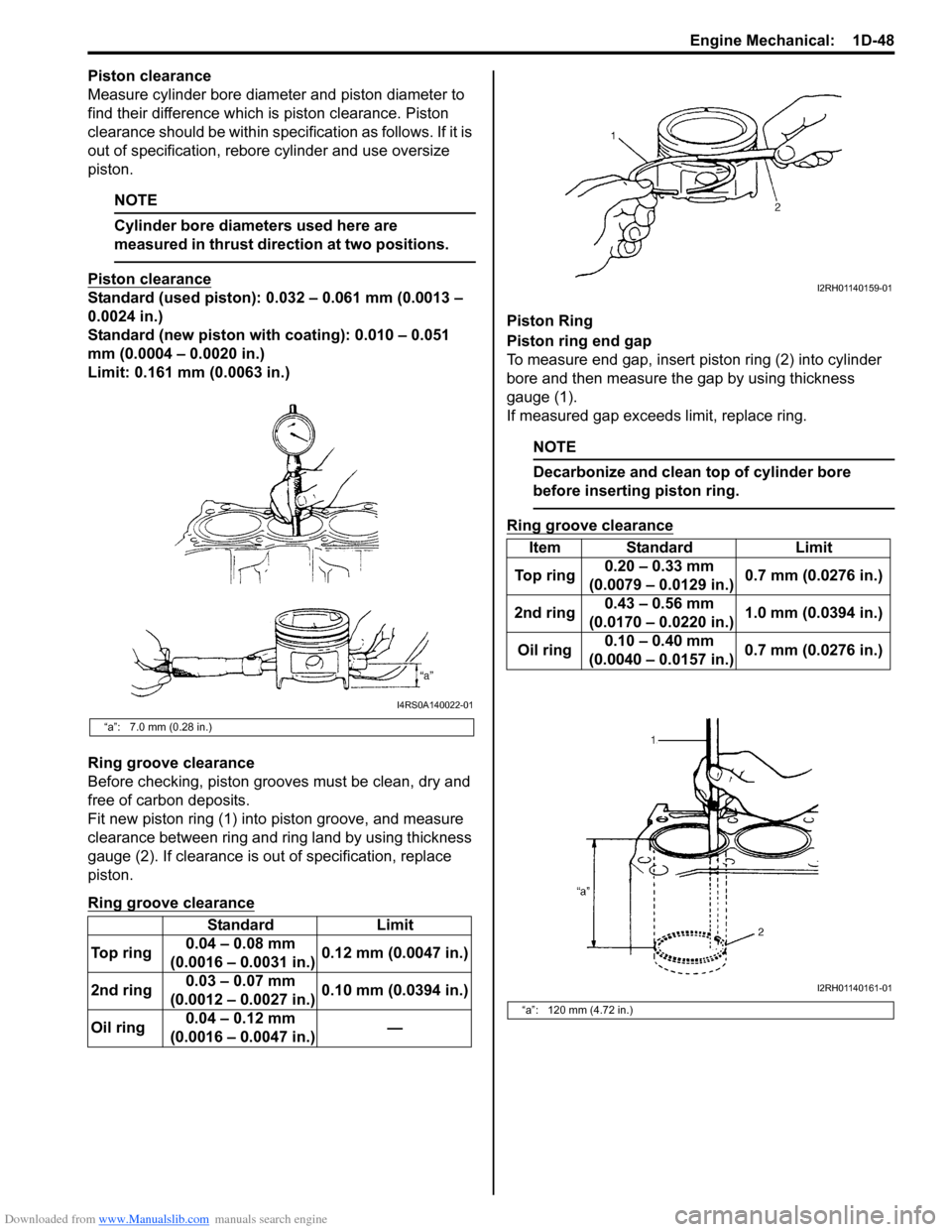
Ring groove clearance
Before checking, piston grooves must be clean, dry and
free of carbon deposits.
Fit new piston ring (1) into piston groove, and measure
clearance between ring and ring land by using thickness
gauge (2). If clearance is ou t of specification, replace
piston.
Ring groove clearance
Piston Ring
Piston ring end gap
To measure end gap, insert piston ring (2) into cylinder
bore and then measure the gap by using thickness
gauge (1).
If measured gap exceeds limit, replace ring.
NOTE
Decarbonize and clean top of cylinder bore
before inserting piston ring.
Ring groove clearance
“a”: 7.0 mm (0.28 in.)
Standard Limit
Top ring 0.04 – 0.08 mm
(0.0016 – 0.0031 in.) 0.12 mm (0.0047 in.)
2nd ring 0.03 – 0.07 mm
(0.0012 – 0.0027 in.) 0.10 mm (0.0394 in.)
Oil ring 0.04 – 0.12 mm
(0.0016 – 0.0047 in.) —
I4RS0A140022-01
Item Standard
Limit
To p r i n g 0.20 – 0.33 mm
(0.0079 – 0.0129 in.) 0.7 mm (0.0276 in.)
2nd ring 0.43 – 0.56 mm
(0.0170 – 0.0220 in.) 1.0 mm (0.0394 in.)
Oil ring 0.10 – 0.40 mm
(0.0040 – 0.0157 in.) 0.7 mm (0.0276 in.)
“a”: 120 mm (4.72 in.)
I2RH01140159-01
I2RH01140161-01
Page 335 of 1496
Downloaded from www.Manualslib.com manuals search engine Engine Mechanical: 1D-50
Connecting rod bearing cap bolt deformation
(Plastic deformation tightening bolt)
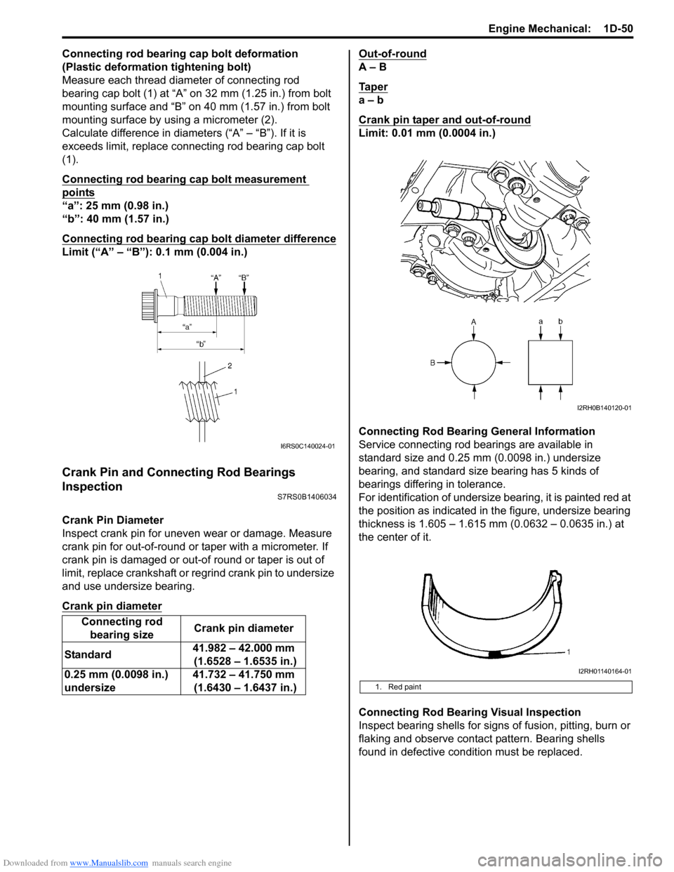
Measure each thread diameter of connecting rod
bearing cap bolt (1) at “A” on 32 mm (1.25 in.) from bolt
mounting surface and “B” on 40 mm (1.57 in.) from bolt
mounting surface by using a micrometer (2).
Calculate difference in diameters (“A” – “B”). If it is
exceeds limit, replace connecting rod bearing cap bolt
(1).
Connecting rod bearing cap bolt measurement
points
“a”: 25 mm (0.98 in.)
“b”: 40 mm (1.57 in.)
Connecting rod bearing cap bolt diameter difference
Limit (“A” – “B”): 0.1 mm (0.004 in.)
Crank Pin and Connecting Rod Bearings
Inspection
S7RS0B1406034
Crank Pin Diameter
Inspect crank pin for uneven wear or damage. Measure
crank pin for out-of-round or taper with a micrometer. If
crank pin is damaged or out-of round or taper is out of
limit, replace crankshaft or regrind crank pin to undersize
and use undersize bearing.
Crank pin diameter
Out-of-round
A – B
Ta p e r
a – b
Crank pin taper and out-of-round
Limit: 0.01 mm (0.0004 in.)
Connecting Rod Bearing General Information
Service connecting rod be arings are available in
standard size and 0.25 mm (0.0098 in.) undersize
bearing, and standard size bearing has 5 kinds of
bearings differing in tolerance.
For identification of undersize bearing, it is painted red at
the position as indicated in the figure, undersize bearing
thickness is 1.605 – 1.615 mm (0.0632 – 0.0635 in.) at
the center of it.
Connecting Rod Bearing Visual Inspection
Inspect bearing shells for signs of fusion, pitting, burn or
flaking and observe contact pattern. Bearing shells
found in defective condition must be replaced.
Connecting rod
bearing size Crank pin diameter
Standard 41.982 – 42.000 mm
(1.6528 – 1.6535 in.)
0.25 mm (0.0098 in.)
undersize 41.732 – 41.750 mm
(1.6430 – 1.6437 in.)
I6RS0C140024-01
1. Red paint
I2RH0B140120-01
I2RH01140164-01