2008 SUZUKI SWIFT Combination
[x] Cancel search: CombinationPage 30 of 1496
![SUZUKI SWIFT 2008 2.G Service Workshop Manual Downloaded from www.Manualslib.com manuals search engine 0A-9 General Information:
[A]
12
4 5
6
7 8
9
3
I4RS0B010002-03
1. Air bag label on driver air bag (inflator) module 6. Air bag label on SDM
2 SUZUKI SWIFT 2008 2.G Service Workshop Manual Downloaded from www.Manualslib.com manuals search engine 0A-9 General Information:
[A]
12
4 5
6
7 8
9
3
I4RS0B010002-03
1. Air bag label on driver air bag (inflator) module 6. Air bag label on SDM
2](/manual-img/20/7607/w960_7607-29.png)
Downloaded from www.Manualslib.com manuals search engine 0A-9 General Information:
[A]
12
4 5
6
7 8
9
3
I4RS0B010002-03
1. Air bag label on driver air bag (inflator) module 6. Air bag label on SDM
2. Air bag label on combination switch and contact coil assembly7. Pretensioner label on seat belt retractor
3. Air bag label on passenger air bag (inflator) module 8. Child seat label (if equipped)
4. Air bag label on side air bag (inflator) module (if equipped) 9. Side/Curtain air bag label on pillar (both right and left sides) (if equipped)
5. Air bag label on curtain air bag (inflator) module (if equipped) [A]: These labels are attached on vehicle equipped with air ba g system only.
Page 52 of 1496
Downloaded from www.Manualslib.com manuals search engine 1A-2 Engine General Information and Diagnosis:
• Be sure to read “Precautions for Electrical Circuit Service in Section 00” befo re inspection and observe
what is written there.
• ECM replacement: When substituting a known-good ECM, check for the
following conditions. Neglec ting this check may cause
damage to a known-good ECM.
– Resistance value of all relays, actuators is as specified respectively.
– MAP sensor, A/C refrigerant pressure sensor and TP sensor are in good condition and none of power
circuits of these sensors is shorted to ground.
• Communication of ECM, BCM, ABS/ESP ® control
module, combination meter, keyless start control
module, steering angle sensor (ESP ® model) and
TCM (A/T model), is esta blished by CAN (Controller
Area Network). (For more detail of CAN
communication for ECM, refer to “CAN
Communication System Description”). Therefore,
handle CAN communication line with care referring to
“Precaution for CAN Communication System in
Section 00”.
• Immobilizer transponder code registration after
replacing ECM
When ECM is replaced with new one or with another
one, make sure to register immobilizer transponder
code to ECM correctly according to “Procedure after
ECM Replacement in Section 10C”.Precautions of ECM Circuit InspectionS7RS0B1100003
• ECM connectors are waterproofed. Each terminal of the ECM connectors is sealed up with the grommet.
Therefore, when measuring ci rcuit voltage, resistance
and/or pulse signal at ECM connector, do not insert
the tester’s probe into th e sealed terminal at the
harness side. When measuring circuit voltage,
resistance and/or pulse signal at ECM connector,
connect the special tool to the ECM connectors. And,
insert the tester’s probe into the special tool’s
connectors at the harness side, and then measure
voltage, resistance and/or pulse signal. Or, ECM and
its circuits may be damaged by water.
• Wire colors of the special tool’s connectors are different from the ones of the ECM connectors.
However, the circuit arrangement of the special tool’s
connectors is same as the one of the ECM
connectors. Therefore, measure circuit voltage and
resistance by identifying the terminal location subject
to the measurement.
Precautions of Electric Throttle Body System
Calibration
S7RS0B1100004
After performing one of works described below, it is
necessary to re-register the completely closed throttle
valve reference position stored in memory of ECM. (For
detailed information, refer to “Description of Electric
Throttle Body System Calibration”.) For the procedure to
register such data in ECM, refer to “Electric Throttle
Body System Calibration in Section 1C”.
• To shut off backup power of ECM for such purposes of battery replacement or “DOME” fuse removal
• To erase DTCs P0122, P01 23, P0222, P0223, P2101,
P2102, P2103, P2111, P2112, P2113, P2119, P2123,
P2127, P2128, P2135 and/or P2138
• To replace ECM
• To replace throttle body and/or accelerator pedal position (APP) sensor assembly
General Description
Statement on Cleanliness and CareS7RS0B1101001
An automobile engine is a combination of many
machined, honed, polished and lapped surfaces with
tolerances that are measured in the thousands of an
millimeter (ten thous ands of an inch).
Accordingly, when any internal engine parts are
serviced, care and cleanliness are important.
It should be understood that proper cleaning and
protection of machined surfaces and friction areas is part
of the repair procedure. This is considered standard
shop practice even if not specifically stated.
• A liberal coating of engine oil should be applied to friction areas during assembly to protect and lubricate
the surfaces on initial operation. • Whenever valve train components, pistons, piston
rings, connecting rods, rod bearings, and crankshaft
journal bearings are removed for service, they should
be retained in order.
At the time of installation, they should be installed in
the same locations and with the same mating
surfaces as when removed.
• Battery cables should be disconnected before any major work is performed on the engine.
Failure to disconnect cables may result in damage to
wire harness or other electrical parts.
Page 55 of 1496
Downloaded from www.Manualslib.com manuals search engine Engine General Information and Diagnosis: 1A-5
Freeze frame data clearance:
The freeze frame data is cleared at the same time as
clearance of DTC.
Non-Euro-OBD
ECM diagnosis troubles which may occur in the area
including the following parts w hen the ignition switch is
ON and the engine is running, and indicates the result by
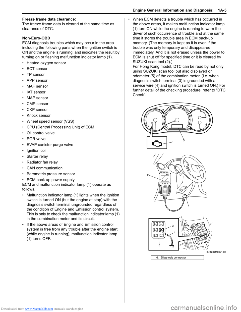
turning on or flashing malfunction indicator lamp (1).
• Heated oxygen sensor
• ECT sensor
•TP sensor
• APP sensor
• MAF sensor
• IAT sensor
• MAP sensor
• CMP sensor
• CKP sensor
• Knock sensor
• Wheel speed sensor (VSS)
• CPU (Central Processing Unit) of ECM
• Oil control valve
• EGR valve
• EVAP canister purge valve
• Ignition coil
• Starter relay
• Radiator fan relay
• CAN communication
• Barometric pressure sensor
• ECM back up power supply
ECM and malfunction indicator lamp (1) operate as
follows.
• Malfunction indicator lamp (1) lights when the ignition switch is turned ON (but t he engine at stop) with the
diagnosis switch terminal ungrounded regardless of
the condition of Engine and Emission control system.
This is only to check the ma lfunction indicator lamp (1)
in the combination meter and its circuit.
• If the above areas of Engine and Emission control system is free from any trouble after the engine start
(while engine is running), malfunction indicator lamp
(1) turns OFF. • When ECM detects a trouble which has occurred in
the above areas, it makes malfunction indicator lamp
(1) turn ON while the engi ne is running to warn the
driver of such occurrence of trouble and at the same
time it stores the trouble area in ECM back-up
memory. (The memory is kept as it is even if the
trouble was only temporary and disappeared
immediately. And it is not erased unless the power to
ECM is shut off for specified time or it is cleared by
SUZUKI scan tool (2).)
For Hong Kong model, DTC can be read by not only
using SUZUKI scan tool but also displayed on
odometer (5) of the combination meter. (i.e. when
diagnosis switch terminal (3) is grounded with a
service wire (4) and ignition switch is turned ON.) For
further detail of the checking procedure, refer to “DTC
Check”.
6. Diagnosis connector
2
1
6 3
5
4
I5RS0C110021-01
Page 57 of 1496
Downloaded from www.Manualslib.com manuals search engine Engine General Information and Diagnosis: 1A-7
CAN Communication System DescriptionS7RS0B1101005
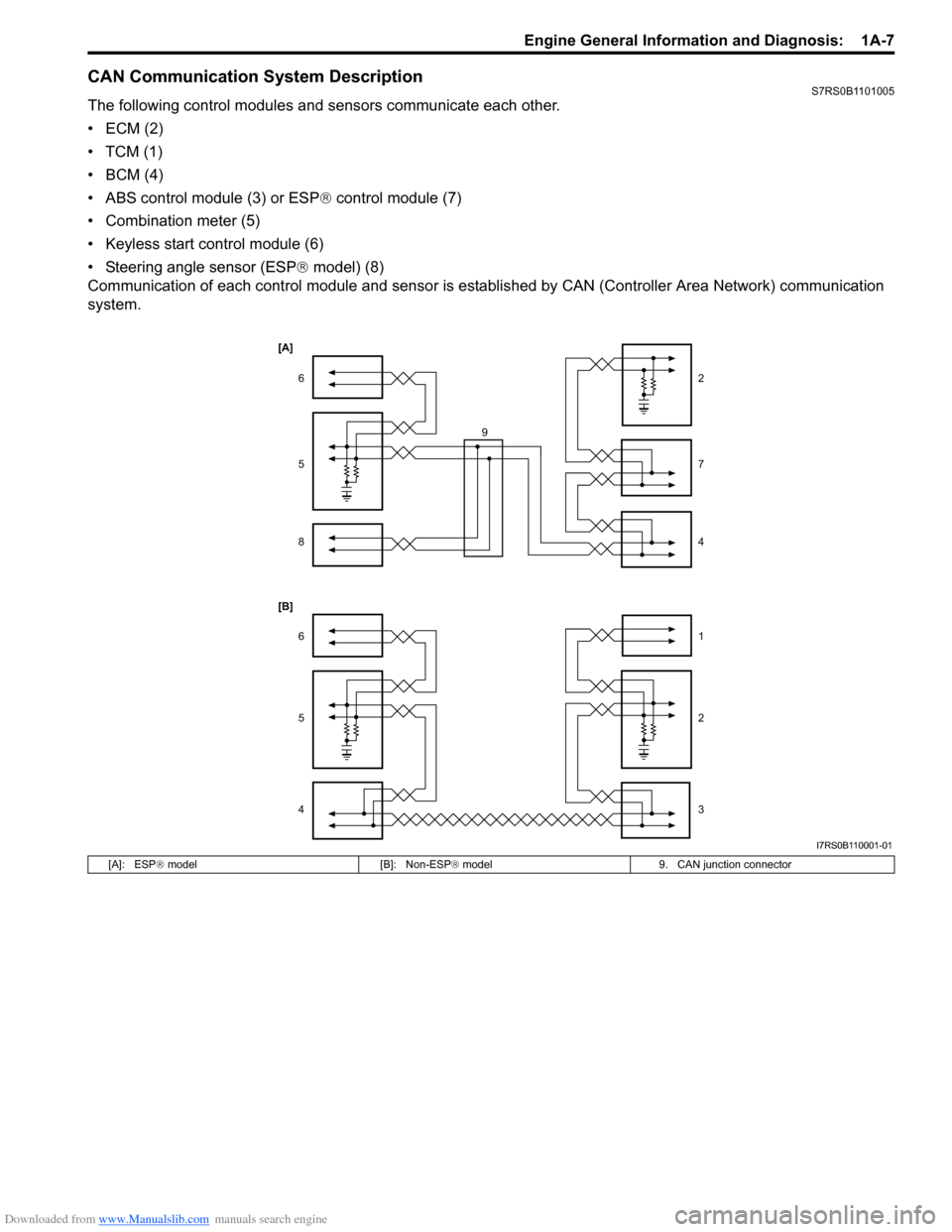
The following control modules and sensors communicate each other.
•ECM (2)
•TCM (1)
•BCM (4)
• ABS control module (3) or ESP® control module (7)
• Combination meter (5)
• Keyless start control module (6)
• Steering angle sensor (ESP ® model) (8)
Communication of each control module and sensor is es tablished by CAN (Controller Area Network) communication
system.
1
2
3
6
5
4
2
7
4
6
5
8
9
[A]
[B]
I7RS0B110001-01
[A]: ESP
® model [B]: Non-ESP ® model 9. CAN junction connector
Page 58 of 1496
Downloaded from www.Manualslib.com manuals search engine 1A-8 Engine General Information and Diagnosis:
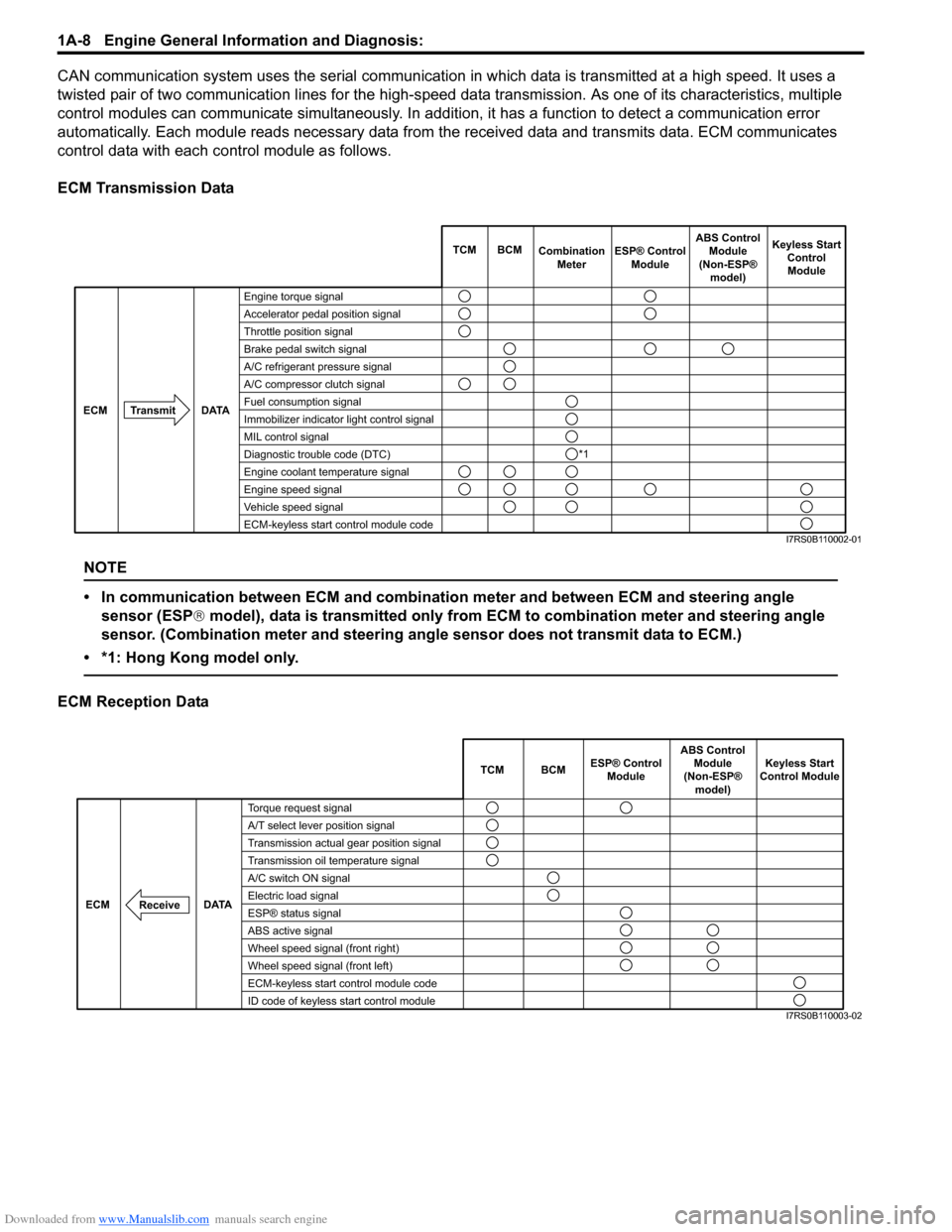
CAN communication system uses the serial communication in which data is transmitted at a high speed. It uses a
twisted pair of two communication lines for the high-speed da ta transmission. As one of its characteristics, multiple
control modules can communicate simultaneously. In addition, it has a function to detect a communication error
automatically. Each module reads necessary data from the received data and transmits data. ECM communicates
control data with each control module as follows.
ECM Transmission Data
NOTE
• In communication between ECM and combination meter and between ECM and steering angle sensor (ESP ® model), data is transmitted only from ECM to combination meter and steering angle
sensor. (Combination meter and steering angle sensor does not transmit data to ECM.)
• *1: Hong Kong model only.
ECM Reception Data
Engine torque signal
Accelerator pedal position signal
Throttle position signal
Brake pedal switch signal
A/C refrigerant pressure signal
A/C compressor clutch signal
Fuel consumption signal
Immobilizer indicator light control signal
MIL control signal
Diagnostic trouble code (DTC)
Engine coolant temperature signal
Engine speed signal
Vehicle speed signal
ECM-keyless start control module code TCM BCM
Combination
Meter Keyless Start
ControlModule
Transmit DATA
ECM
ESP® Control
Module ABS Control
Module
(Non-ESP® model)
*1
I7RS0B110002-01
TCM BCM Keyless Start
Control Module
DATA
ECM
Torque request signal
A/T select lever position signal
Transmission actual gear position signal
Transmission oil temperature signal
A/C switch ON signal
Electric load signal
ESP® status signal
ABS active signal
Wheel speed signal (front right)
Wheel speed signal (front left)
ECM-keyless start control module code
ID code of keyless start control module
Receive
ABS Control
Module
(Non-ESP® model)
ESP® Control
Module
I7RS0B110003-02
Page 61 of 1496
Downloaded from www.Manualslib.com manuals search engine Engine General Information and Diagnosis: 1A-11
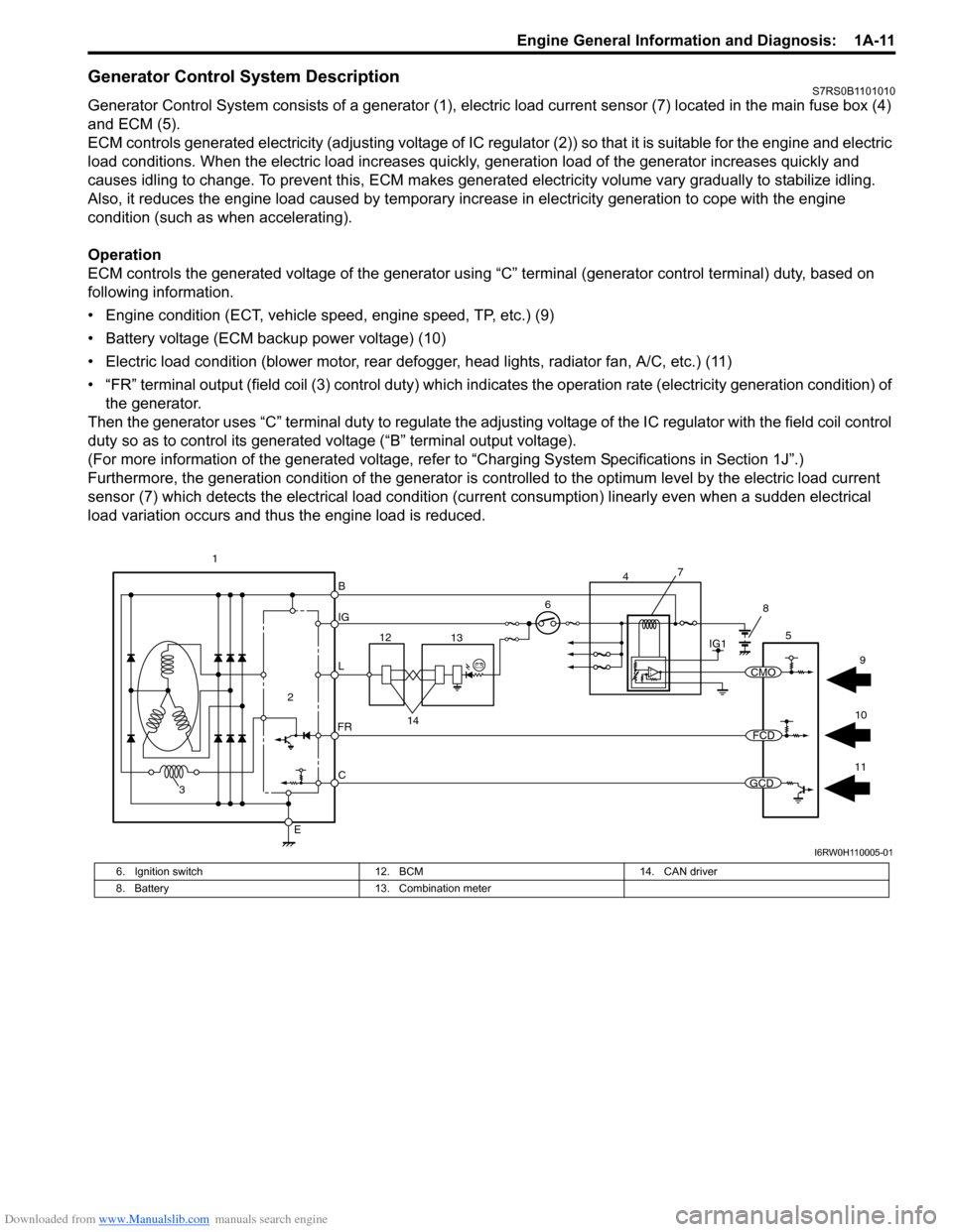
Generator Control System DescriptionS7RS0B1101010
Generator Control System consists of a generator (1), electric load current sensor (7) located in the main fuse box (4)
and ECM (5).
ECM controls generated electricity (adjusting voltage of IC regulator (2)) so that it is suitable for the engine and electric
load conditions. When the electric load increases quickly, generation load of the generator increases quickly and
causes idling to change. To prevent this, ECM makes generated electricity volume vary gradually to stabilize idling.
Also, it reduces the engine load caused by temporary incr ease in electricity generation to cope with the engine
condition (such as when accelerating).
Operation
ECM controls the generated voltage of the generator using “C” terminal (generator control terminal) duty, based on
following information.
• Engine condition (ECT, vehicle speed, engine speed, TP, etc.) (9)
• Battery voltage (ECM backup power voltage) (10)
• Electric load condition (blower motor, rear defogger, head lights, radiator fan, A/C, etc.) (11)
• “FR” terminal output (field coil (3) cont rol duty) which indicates the operation rate (electricity generation condition) of
the generator.
Then the generator uses “C” terminal duty to regulate the adju sting voltage of the IC regulator with the field coil control
duty so as to control its generated voltage (“B” terminal output voltage).
(For more information of the generated voltage, refer to “Charging System Specifications in Section 1J”.)
Furthermore, the generation condition of the generator is co ntrolled to the optimum level by the electric load current
sensor (7) which detects the electrical load condition (cur rent consumption) linearly even when a sudden electrical
load variation occurs and thus the engine load is reduced.
B
IG
L
C
E
6
2
3
FR
5
12 13
14
1IG1
7
4
8
11
10 9
CMO
FCD
GCD
I6RW0H110005-01
6. Ignition switch
12. BCM 14. CAN driver
8. Battery 13. Combination meter
Page 62 of 1496
Downloaded from www.Manualslib.com manuals search engine 1A-12 Engine General Information and Diagnosis:
Electronic Control System DescriptionS7RS0B1101011
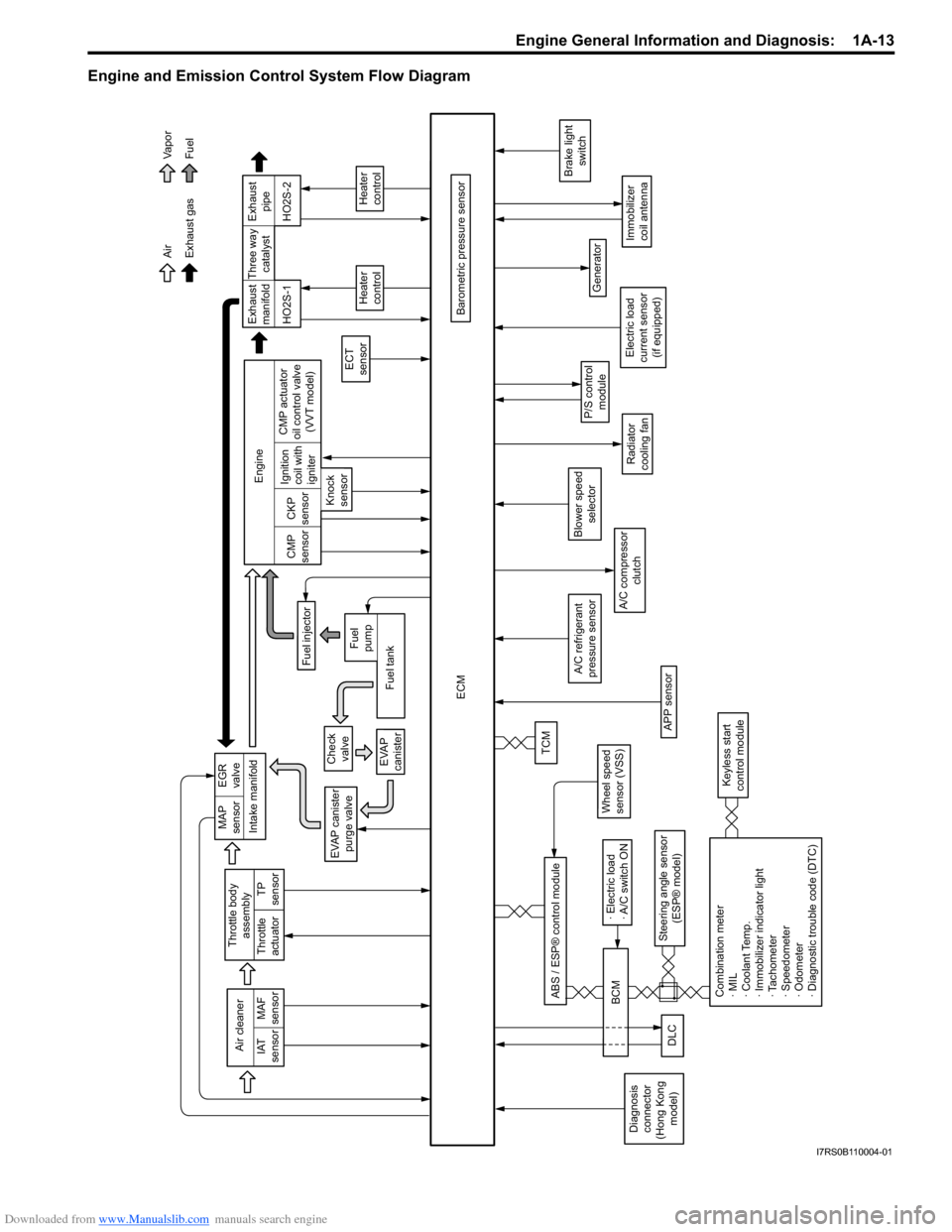
The electronic control system consists of 1) various sensors which detect the state of engine and driving conditions, 2)
ECM which controls various devices ac cording to the signals from the sensors and 3) various controlled devices.
Functionally, it is divided into the following sub systems:
• Fuel injection control system
• Ignition control system
• Electric throttle body control system
• Fuel pump control system
• Radiator cooling fan control system
• Evaporative emission control system
• EGR system
• Oxygen sensor heater control system
• A/C control system (A/C model)
• Camshaft position control system
• Immobilizer control system
• Generator control system
• Controller (computer) communication system
Especially, ECM, BCM, combination meter, TCM (A/T model), ABS/ESP ® control module, steering angle sensor
(ESP® model) and keyless start control module (if equipped) intercommunicate by means of CAN communication.
Page 63 of 1496
Downloaded from www.Manualslib.com manuals search engine Engine General Information and Diagnosis: 1A-13
Engine and Emission Control System Flow Diagram
Intake manifold
Exhaust gas AirFuel
Va p o r
EVAP canister purge valve
ECM
Barometric pressure sensor
A/C compressor clutch
Generator
Immobilizer
coil antenna
P/S controlmodule
Brake light switch
Air cleaner
IAT
sensor MAF
sensor
A/C refrigerant
pressure sensor
TP
sensor
Throttle body
assembly
Throttle
actuator
Wheel speed
sensor (VSS)
Steering angle sensor (ESP® model)
ABS / ESP® control module
Blower speed
selector
MAP
sensor EGR
valve
Check valve
EVAP
canisterTCM
Exhaust
manifold Exhaust
pipe
Fuel injector
ECT
sensor
Heater
control
HO2S-1 HO2S-2
Engine
CMP
sensor CKP
sensor
Knock
sensor Ignition
coil with
igniter
Fuel tank
Fuel
pump CMP actuator
oil control valve (VVT model) Three way
catalyst
Heater
control
Radiator
cooling fan
Combination meter
· MIL
· Coolant Temp.
· Immobilizer indicator light
· Tachometer
· Speedometer
· Odometer
· Diagnostic trouble code (DTC)
Keyless start
control module
DLC
· Electric load
· A/C switch ON
BCM
Diagnosis
connector
(Hong Kong model) Electric load
current sensor (if equipped)
APP sensor
I7RS0B110004-01