2008 SUZUKI SWIFT DTC CHECK
[x] Cancel search: DTC CHECKPage 1126 of 1496
Downloaded from www.Manualslib.com manuals search engine 8B-88 Air Bag System:
NOTE
Upon completion of inspection and repair work, perform the following items.
• Reconnect all air bag system components, ensure all components are properly mounted.
• Clear DTCs referring to “DTC Clearance”, if any.
• Repeat “Air Bag Diagnostic System Check” to confirm that the trouble has been corrected.
DTC B1363 / B1367: Driver / Passenger Side Curtain-Air Bag Initiator Circuit Short to GroundS7RS0B8204045
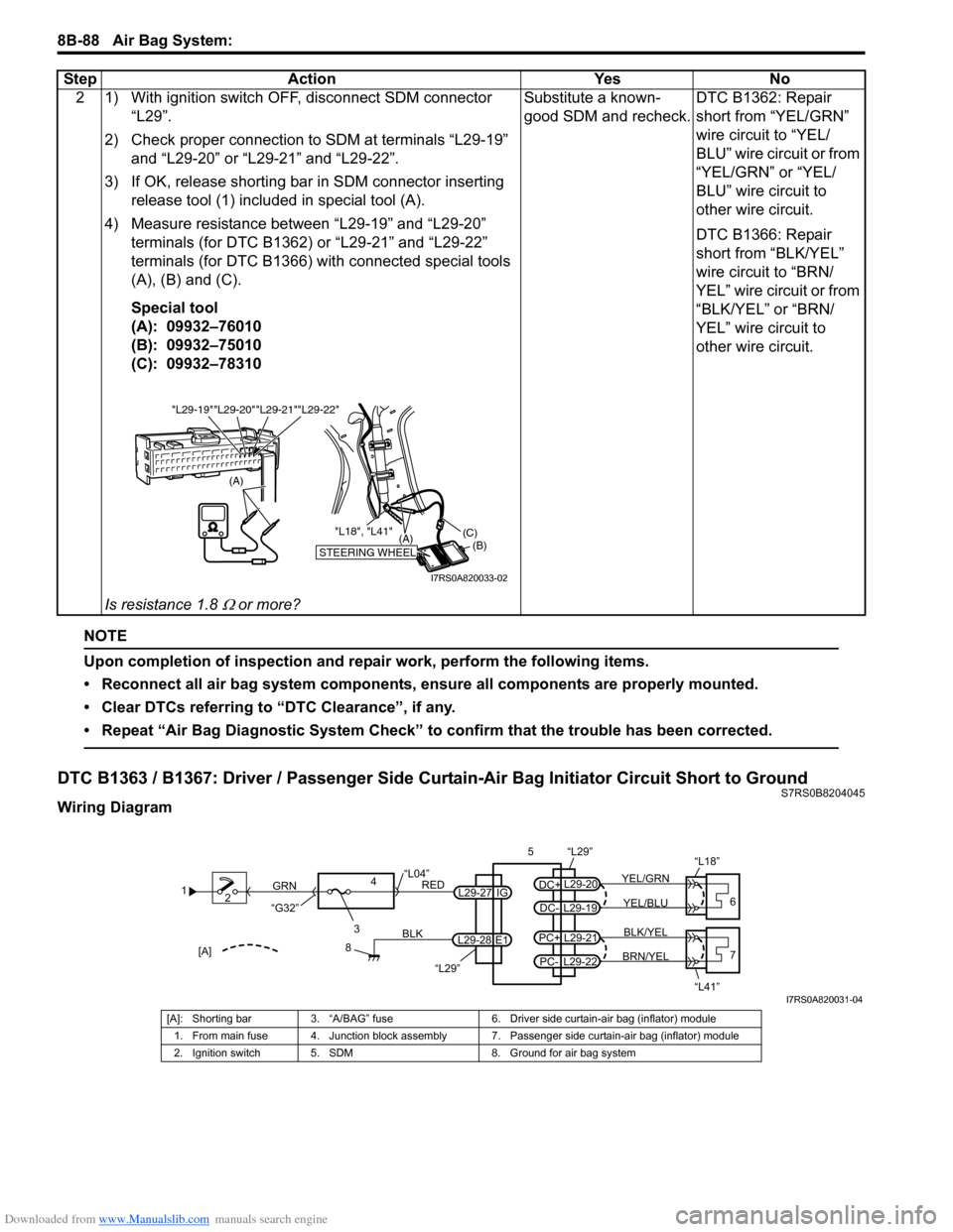
Wiring Diagram2 1) With ignition switch OFF, disconnect SDM connector
“L29”.
2) Check proper connection to SDM at terminals “L29-19” and “L29-20” or “L29-21” and “L29-22”.
3) If OK, release shorting bar in SDM connector inserting
release tool (1) included in special tool (A).
4) Measure resistance between “L29-19” and “L29-20” terminals (for DTC B1362) or “L29-21” and “L29-22”
terminals (for DTC B1366) with connected special tools
(A), (B) and (C).
Special tool
(A): 09932–76010
(B): 09932–75010
(C): 09932–78310
Is resistance 1.8
Ω or more? Substitute a known-
good SDM and recheck.
DTC B1362: Repair
short from “YEL/GRN”
wire circuit to “YEL/
BLU” wire circuit or from
“YEL/GRN” or “YEL/
BLU” wire circuit to
other wire circuit.
DTC B1366: Repair
short from “BLK/YEL”
wire circuit to “BRN/
YEL” wire circuit or from
“BLK/YEL” or “BRN/
YEL” wire circuit to
other wire circuit.
Step Action Yes No
(A)
"L29-20""L29-21""L29-22"
"L29-19"
STEERING WHEEL(B)
(C)
(A)
"L18", "L41"
I7RS0A820033-02
1
2
3
GRN
RED
8
BLK
L29-27
L29-28 IG
E1
4
“L29”
“L04”
“G32”
“L29”
L29-20
DC+
L29-19
DC-YEL/BLU
YEL/GRN
56
“L18”
L29-21
PC+
L29-22
PC-BRN/YEL BLK/YEL7
“L41”[A]
I7RS0A820031-04
[A]: Shorting bar 3. “A/BAG” fuse 6. Driver side curtain-air bag (inflator) module
1. From main fuse 4. Junction block assembly 7. Passenger side curtain-air bag (inflator) module
2. Ignition switch 5. SDM 8. Ground for air bag system
Page 1127 of 1496
Downloaded from www.Manualslib.com manuals search engine Air Bag System: 8B-89
CAUTION!
• Be sure to perform “Air Bag Diagnostic System Check” before starting diagnosis according to flow.
• When measurement of resistance or voltage is required in this flow, use a tester along with a correct terminal adapter from special tool (Connector test adapter kit).
• When a check for proper connection is required, refer to “Inspection of Intermittent and Poor Connections”.
• If there is open circuit in the air bag wire harnes s, connector or terminal is found damaged, replace
the wire harness, connector and terminal as an assembly.
DTC Will Set when
The voltage measured at side curtain-air bag (driver or passenger) initiator circuit is below a specified value for
specified time.
Flow Test Description
Step 1: Check whether malfunction is in side curtain-air bag (inflator) module.
Step 2: Check side curtain-air bag initiator circuit.
DTC Troubleshooting
Step Action YesNo
1 1) With ignition switch OFF, remove rear side upper trim of driver or passenger side and disconnect side curtain-air
bag (inflator) module connector.
2) Check proper connection to side-air bag (inflator) module at terminals in “L18” or “L41” connector.
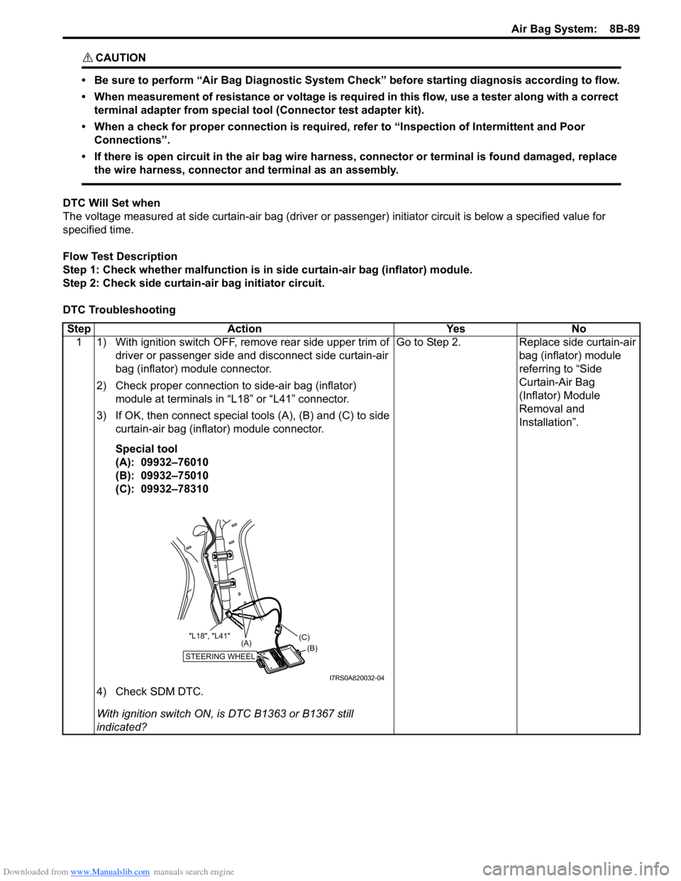
3) If OK, then connect special tools (A), (B) and (C) to side curtain-air bag (inflator) module connector.
Special tool
(A): 09932–76010
(B): 09932–75010
(C): 09932–78310
4) Check SDM DTC.
With ignition switch ON, is DTC B1363 or B1367 still
indicated? Go to Step 2.
Replace side curtain-air
bag (inflator) module
referring to “Side
Curtain-Air Bag
(Inflator) Module
Removal and
Installation”.
STEERING WHEEL(B)
(C)
(A)
"L18", "L41"
I7RS0A820032-04
Page 1128 of 1496
Downloaded from www.Manualslib.com manuals search engine 8B-90 Air Bag System:
NOTE
Upon completion of inspection and repair work, perform the following items.
• Reconnect all air bag system components, ensure all components are properly mounted.
• Clear DTCs referring to “DTC Clearance”, if any.
• Repeat “Air Bag Diagnostic System Check” to confirm that the trouble has been corrected.
DTC B1364 / B1368: Driver / Passenger Side Curtain-Air Bag Initiator Circuit Short to Power CircuitS7RS0B8204046
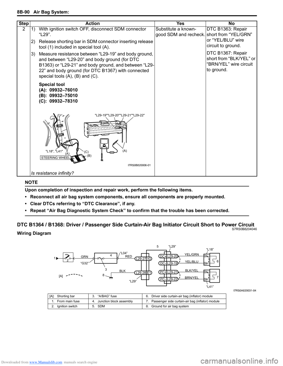
Wiring Diagram2 1) With ignition switch OFF, disconnect SDM connector
“L29”.
2) Release shorting bar in SDM connector inserting release tool (1) included in special tool (A).
3) Measure resistance between “L29-19” and body ground, and between “L29-20” and body ground (for DTC
B1363) or “L29-21” and body ground, and between “L29-
22” and body ground (for DTC B1367) with connected
special tools (A), (B) and (C).
Special tool
(A): 09932–76010
(B): 09932–75010
(C): 09932–78310
Is resistance infinity? Substitute a known-
good SDM and recheck.
DTC B1363: Repair
short from “YEL/GRN”
or “YEL/BLU” wire
circuit to ground.
DTC B1367: Repair
short from “BLK/YEL” or
“BRN/YEL” wire circuit
to ground.
Step Action Yes No
"L29-20""L29-21""L29-22"
"L29-19"
STEERING WHEEL(B)
(C)
(A)
"L18", "L41"
(A)
I7RS0B820006-01
1
2
3
GRN
RED
8
BLK
L29-27
L29-28 IG
E1
4
“L29”
“L04”
“G32”
“L29”
L29-20
DC+
L29-19
DC-YEL/BLU
YEL/GRN
56
“L18”
L29-21
PC+
L29-22
PC-BRN/YEL BLK/YEL7
“L41”[A]
I7RS0A820031-04
[A]: Shorting bar 3. “A/BAG” fuse 6. Driver side curtain-air bag (inflator) module
1. From main fuse 4. Junction block assembly 7. Passenger side curtain-air bag (inflator) module
2. Ignition switch 5. SDM 8. Ground for air bag system
Page 1129 of 1496
Downloaded from www.Manualslib.com manuals search engine Air Bag System: 8B-91
CAUTION!
• Be sure to perform “Air Bag Diagnostic System Check” before starting diagnosis according to flow.
• When measurement of resistance or voltage is required in this flow, use a tester along with a correct terminal adapter from special tool (Connector test adapter kit).
• When a check for proper connection is required, refer to “Inspection of Intermittent and Poor Connections”.
• If there is open circuit in the air bag wire harnes s, connector or terminal is found damaged, replace
the wire harness, connector and terminal as an assembly.
DTC Will Set when
The voltage measured at side curtain-air bag (driver or passenger) initiator circuit is above a specified value for
specified time.
Flow Test Description
Step 1: Check whether malfunction is in side curtain-air bag (inflator) module.
Step 2: Check side curtain-air bag initiator circuit.
DTC Troubleshooting
Step Action YesNo
1 1) With ignition switch OFF, remove rear side upper trim of driver or passenger side and disconnect side curtain-air
bag (inflator) module connector.
2) Check proper connection to side curtain-air bag (inflator) module at terminals in “L18” or “L41” connector.
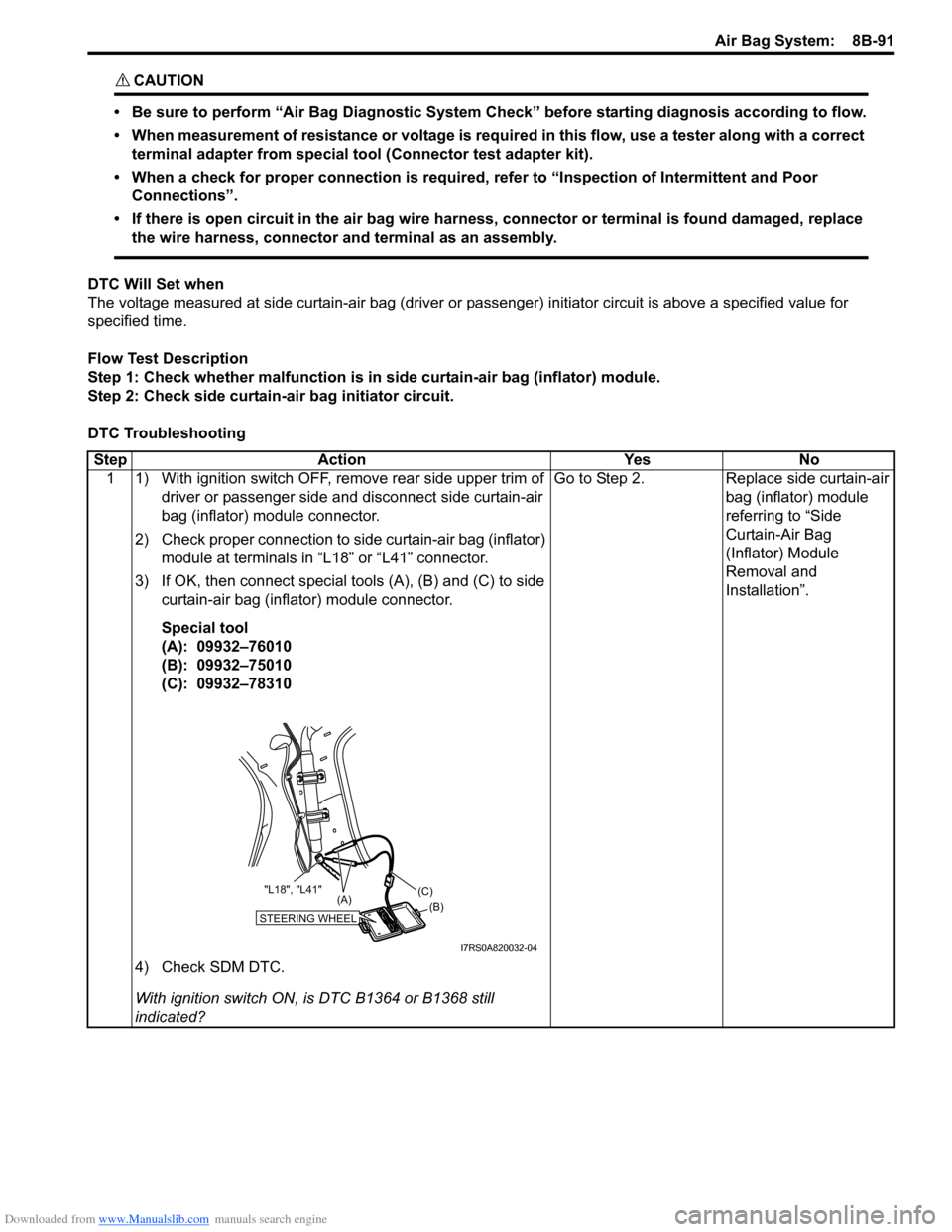
3) If OK, then connect special tools (A), (B) and (C) to side curtain-air bag (inflator) module connector.
Special tool
(A): 09932–76010
(B): 09932–75010
(C): 09932–78310
4) Check SDM DTC.
With ignition switch ON, is DTC B1364 or B1368 still
indicated? Go to Step 2.
Replace side curtain-air
bag (inflator) module
referring to “Side
Curtain-Air Bag
(Inflator) Module
Removal and
Installation”.
STEERING WHEEL(B)
(C)
(A)
"L18", "L41"
I7RS0A820032-04
Page 1130 of 1496
Downloaded from www.Manualslib.com manuals search engine 8B-92 Air Bag System:
NOTE
Upon completion of inspection and repair work, perform the following items.
• Reconnect all air bag system components, ensure all components are properly mounted.
• Clear DTCs referring to “DTC Clearance”, if any.
• Repeat “Air Bag Diagnostic System Check” to confirm that the trouble has been corrected.
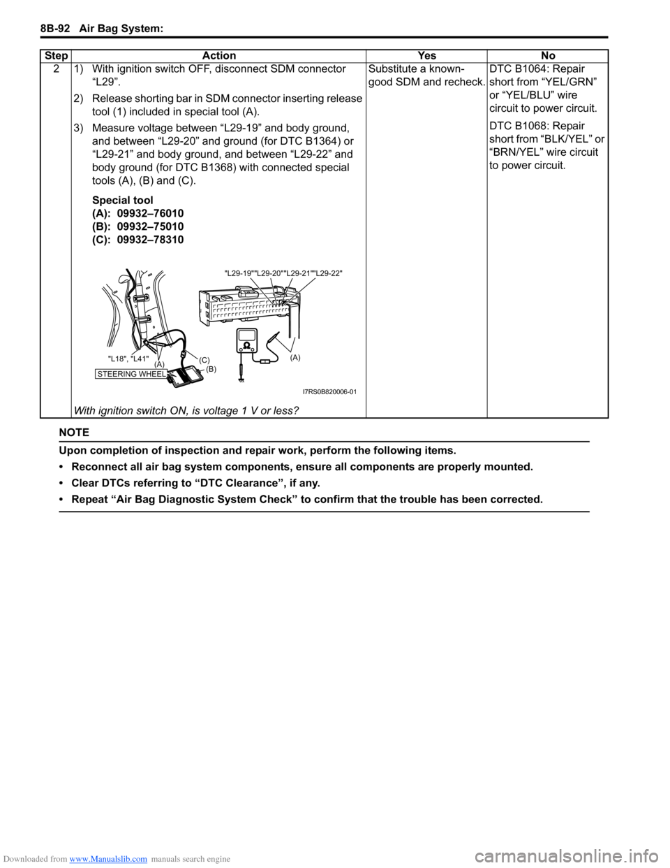
2 1) With ignition switch OFF, disconnect SDM connector “L29”.
2) Release shorting bar in SDM connector inserting release tool (1) included in special tool (A).
3) Measure voltage between “L29-19” and body ground, and between “L29-20” and ground (for DTC B1364) or
“L29-21” and body ground, and between “L29-22” and
body ground (for DTC B1368) with connected special
tools (A), (B) and (C).
Special tool
(A): 09932–76010
(B): 09932–75010
(C): 09932–78310
With ignition switch ON, is voltage 1 V or less? Substitute a known-
good SDM and recheck.
DTC B1064: Repair
short from “YEL/GRN”
or “YEL/BLU” wire
circuit to power circuit.
DTC B1068: Repair
short from “BLK/YEL” or
“BRN/YEL” wire circuit
to power circuit.
Step Action Yes No
"L29-20""L29-21""L29-22"
"L29-19"
STEERING WHEEL(B)
(C)
(A)
"L18", "L41"
(A)
I7RS0B820006-01
Page 1135 of 1496
Downloaded from www.Manualslib.com manuals search engine Air Bag System: 8B-97
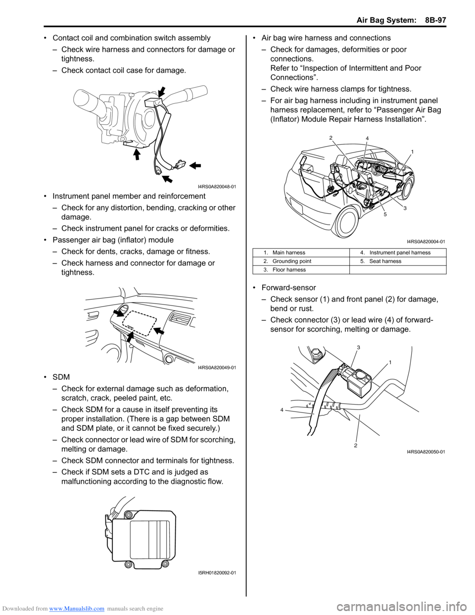
• Contact coil and combination switch assembly
– Check wire harness and connectors for damage or tightness.
– Check contact coil case for damage.
• Instrument panel member and reinforcement – Check for any distortion, bending, cracking or other damage.
– Check instrument panel fo r cracks or deformities.
• Passenger air bag (inflator) module
– Check for dents, cracks, damage or fitness.
– Check harness and connector for damage or tightness.
•SDM – Check for external damage such as deformation, scratch, crack, peeled paint, etc.
– Check SDM for a cause in itself preventing its proper installation. (There is a gap between SDM
and SDM plate, or it cannot be fixed securely.)
– Check connector or lead wire of SDM for scorching, melting or damage.
– Check SDM connector and terminals for tightness.
– Check if SDM sets a DTC and is judged as malfunctioning according to the diagnostic flow. • Air bag wire harness and connections
– Check for damages, deformities or poor connections.
Refer to “Inspection of Intermittent and Poor
Connections”.
– Check wire harness clamps for tightness.
– For air bag harness including in instrument panel harness replacement, refer to “Passenger Air Bag
(Inflator) Module Repair Harness Installation”.
• Forward-sensor – Check sensor (1) and front panel (2) for damage, bend or rust.
– Check connector (3) or lead wire (4) of forward- sensor for scorching, melting or damage.
I4RS0A820048-01
I4RS0A820049-01
I5RH01820092-01
1. Main harness 4. Instrument panel harness
2. Grounding point 5. Seat harness
3. Floor harness
1
2
3
4
5
I4RS0A820004-01
1
3
2
4
I4RS0A820050-01
Page 1296 of 1496
Downloaded from www.Manualslib.com manuals search engine 9C-1 Instrumentation / Driver Info. / Horn:
Body, Cab and Accessories
Instrumentation / Driver Info. / Horn
Precautions
Precautions in Diagnosing Troubles for Combination MeterS7RS0B9300001
Combination meter uses signals (information) from each control module by CAN communication to control
speedometer, tachometer, engine coolant temp meter, warning light and indicator light (other than air bag warning
light, high beam indicator light, EPS warn ing light and turn signal indicator light). Therefore, check that no DTC is
detected in each module before performing combination me ter symptom diagnosis. If any DTC is detected, correct
trouble indicated by that DTC troubleshooting first.
General Description
CAN Communication System DescriptionS7RS0B9301001
Refer to “CAN Communication System Description in Section 1A” for Can communication system description.
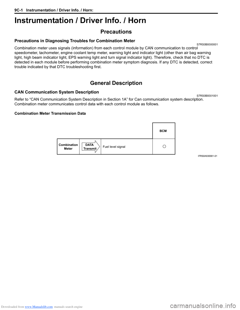
Combination meter communicates control data with each control module as follows.
Combination Meter Transmission Data
BCM
Combination Meter DATA
TransmitFuel level signal
I7RS0A930001-01
Page 1306 of 1496
Downloaded from www.Manualslib.com manuals search engine 9C-11 Instrumentation / Driver Info. / Horn:
Information Display Symptom Diagnosis (If Equipped)S7RS0B9304015
NOTE
This thermometer indicates the ambient temperature in back of front bumper member. Under any one
of the following listed conditions, however, even when the ambient temperature goes up, the
thermometer display does not rise so as to correct the rise of the ambient temperature caused by the
radiant heat of the engine. When the ambient temperature drops, the thermometer reading follows the
change in the temperature.
Be sure to bear this in mind when diagnosing trouble.
• The vehicle speed is 30 km/h (18 mph) or lower.
• Vehicle speed signal is faulty.
• The ignition switch is turned on again within 2 hours.
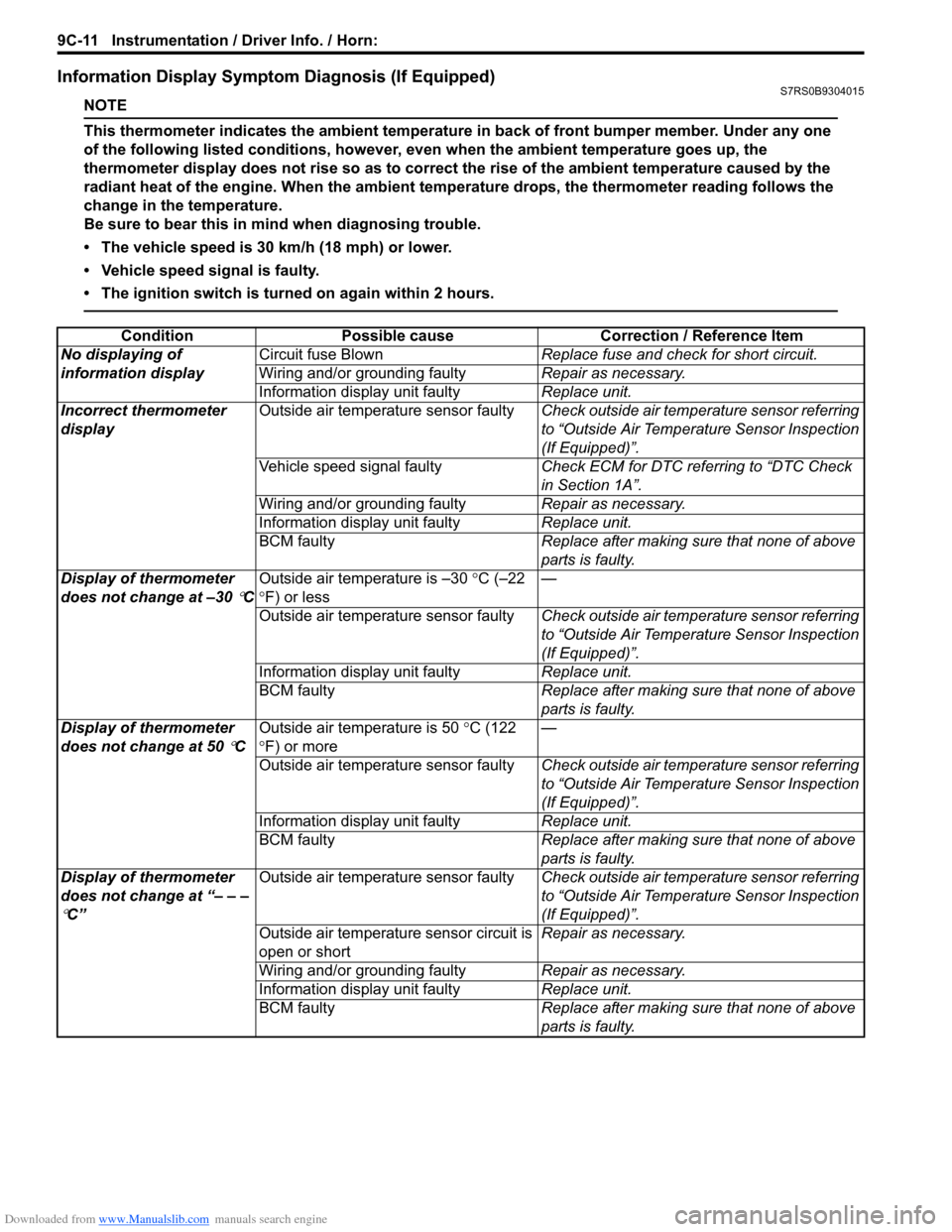
ConditionPossible cause Correction / Reference Item
No displaying of
information display Circuit fuse Blown
Replace fuse and check for short circuit.
Wiring and/or grounding faulty Repair as necessary.
Information display unit faulty Replace unit.
Incorrect thermometer
display Outside air temperature sensor faulty
Check outside air temperature sensor referring
to “Outside Air Temperature Sensor Inspection
(If Equipped)”.
Vehicle speed signal faulty Check ECM for DTC referring to “DTC Check
in Section 1A”.
Wiring and/or grounding faulty Repair as necessary.
Information display unit faulty Replace unit.
BCM faulty Replace after making sure that none of above
parts is faulty.
Display of thermometer
does not change at –30
°C Outside air temperature is –30
°C (–22
° F) or less —
Outside air temperature sensor faulty Check outside air temperature sensor referring
to “Outside Air Temperature Sensor Inspection
(If Equipped)”.
Information display unit faulty Replace unit.
BCM faulty Replace after making sure that none of above
parts is faulty.
Display of thermometer
does not change at 50
°C Outside air temperature is 50
°C (122
° F) or more —
Outside air temperature sensor faulty Check outside air temperature sensor referring
to “Outside Air Temperature Sensor Inspection
(If Equipped)”.
Information display unit faulty Replace unit.
BCM faulty Replace after making sure that none of above
parts is faulty.
Display of thermometer
does not change at “– – –
°C” Outside air temperature sensor faulty
Check outside air temperature sensor referring
to “Outside Air Temperature Sensor Inspection
(If Equipped)”.
Outside air temperature sensor circuit is
open or short Repair as necessary.
Wiring and/or grounding faulty Repair as necessary.
Information display unit faulty Replace unit.
BCM faulty Replace after making sure that none of above
parts is faulty.