2008 SUZUKI SWIFT Grounds
[x] Cancel search: GroundsPage 110 of 1496
Downloaded from www.Manualslib.com manuals search engine 1A-60 Engine General Information and Diagnosis:
4MAF sensor output voltage check
1) Turn OFF ignition switch.
2) Remove ECM from its br acket with ECM connectors
connected.
3) Measure voltage between “C37-26” and “C37-27” terminals of ECM connector referring to “MAF and IAT
Sensor On-Vehicle Inspection in Section 1C”.
Is each value within specified range? Poor “C37-26” and/or
“C37-27” terminal
connection.
If OK, substitute a
known-good ECM and
recheck.
Go to Step 5.
5 MAF sensor power supply voltage check
1) Disconnect connector from MAF and IAT sensor with
ignition switch turned OFF.
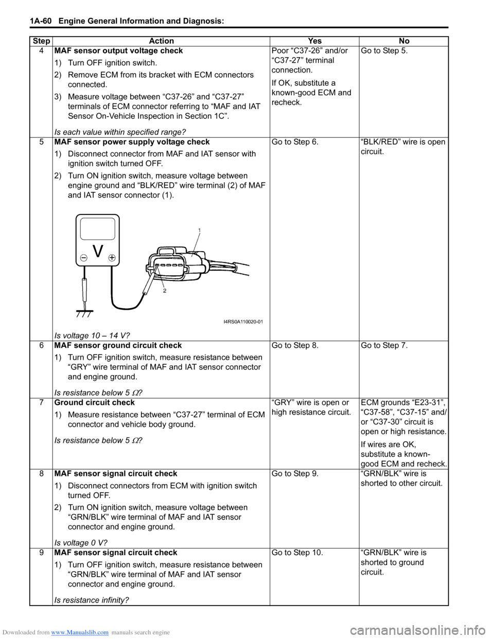
2) Turn ON ignition switch, measure voltage between engine ground and “BLK/RED” wire terminal (2) of MAF
and IAT sensor connector (1).
Is voltage 10 – 14 V? Go to Step 6. “BLK/RED” wire is open
circuit.
6 MAF sensor ground circuit check
1) Turn OFF ignition switch, measure resistance between
“GRY” wire terminal of MAF and IAT sensor connector
and engine ground.
Is resistance below 5
Ω? Go to Step 8.
Go to Step 7.
7 Ground circuit check
1) Measure resistance between “C37-27” terminal of ECM
connector and vehicle body ground.
Is resistance below 5
Ω? “GRY” wire is open or
high resistance circuit.
ECM grounds “E23-31”,
“C37-58”, “C37-15” and/
or “C37-30” circuit is
open or high resistance.
If wires are OK,
substitute a known-
good ECM and recheck.
8 MAF sensor signal circuit check
1) Disconnect connectors from ECM with ignition switch
turned OFF.
2) Turn ON ignition switch, measure voltage between “GRN/BLK” wire terminal of MAF and IAT sensor
connector and engine ground.
Is voltage 0 V? Go to Step 9. “GRN/BLK” wire is
shorted to other circuit.
9 MAF sensor signal circuit check
1) Turn OFF ignition switch, measure resistance between
“GRN/BLK” wire terminal of MAF and IAT sensor
connector and engine ground.
Is resistance infinity? Go to Step 10. “GRN/BLK” wire is
shorted to ground
circuit.
Step Action Yes No
I4RS0A110020-01
Page 112 of 1496
Downloaded from www.Manualslib.com manuals search engine 1A-62 Engine General Information and Diagnosis:
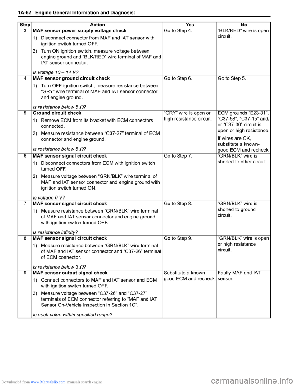
3MAF sensor power supply voltage check
1) Disconnect connector from MAF and IAT sensor with
ignition switch turned OFF.
2) Turn ON ignition switch, measure voltage between engine ground and “BLK/RED” wire terminal of MAF and
IAT sensor connector.
Is voltage 10 – 14 V? Go to Step 4. “BLK/RED” wire is open
circuit.
4 MAF sensor ground circuit check
1) Turn OFF ignition switch, measure resistance between
“GRY” wire terminal of MAF and IAT sensor connector
and engine ground.
Is resistance below 5
Ω? Go to Step 6.
Go to Step 5.
5 Ground circuit check
1) Remove ECM from its br acket with ECM connectors
connected.
2) Measure resistance between “C37-27” terminal of ECM connector and engine ground.
Is resistance below 5
Ω? “GRY” wire is open or
high resistance circuit.
ECM grounds “E23-31”,
“C37-58”, “C37-15” and/
or “C37-30” circuit is
open or high resistance.
If wires are OK,
substitute a known-
good ECM and recheck.
6 MAF sensor signal circuit check
1) Disconnect connectors from ECM with ignition switch
turned OFF.
2) Measure voltage between “GRN/BLK” wire terminal of MAF and IAT sensor connector and engine ground with
ignition switch turned ON.
Is voltage 0 V? Go to Step 7. “GRN/BLK” wire is
shorted to other circuit.
7 MAF sensor signal circuit check
1) Measure resistance between “GRN/BLK” wire terminal
of MAF and IAT sensor connector and engine ground
with ignition swit ch turned OFF.
Is resistance infinity? Go to Step 8.
“GRN/BLK” wire is
shorted to ground
circuit.
8 MAF sensor signal circuit check
1) Measure resistance between “GRN/BLK” wire terminal
of MAF and IAT sensor connector and “C37-26” terminal
of ECM connector.
Is resistance below 3
Ω? Go to Step 9.
“GRN/BLK” wire is open
or high resistance
circuit.
9 MAF sensor output signal check
1) Connect connectors to MAF and IAT sensor and ECM
with ignition swit ch turned OFF.
2) Measure voltage between “C37-26” and “C37-27” terminals of ECM connector referring to “MAF and IAT
Sensor On-Vehicle Inspection in Section 1C”.
Is each value within specified range? Substitute a known-
good ECM and recheck.
Faulty MAF and IAT
sensor.
Step
Action YesNo
Page 113 of 1496
Downloaded from www.Manualslib.com manuals search engine Engine General Information and Diagnosis: 1A-63
DTC P0103: Mass or Volume Air Flow Circuit High InputS7RS0B1104019
Wiring Diagram
Refer to “DTC P0101: Mass or Volume Air Flow Circuit Range / Performance”.
DTC Detecting Condition and Trouble Area
DTC Confirmation Procedure1) With ignition switch turned OFF, connect scan tool.
2) Turn ON ignition switch and clear DTC using scan tool.
3) Start engine and run it for 10 sec.
4) Check DTC.
DTC Troubleshooting
NOTE
• When measuring circuit voltage, resistance and/ or pulse signal at ECM connector, connect the
special tool to ECM and/or the ECM connectors re ferring to “Inspection of ECM and Its Circuits”.
• Upon completion of inspection and repair work, perform “DTC Confirmation Procedure” and confirm that the trouble has been corrected.
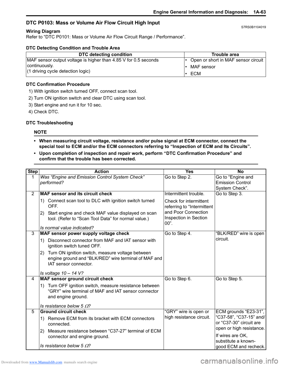
DTC detecting condition Trouble area
MAF sensor output voltage is higher than 4.85 V for 0.5 seconds
continuously.
(1 driving cycle detection logic) • Open or short in MAF sensor circuit
• MAF sensor
•ECM
Step
Action YesNo
1 Was “Engine and Emission Control System Check”
performed? Go to Step 2.
Go to “Engine and
Emission Control
System Check”.
2 MAF sensor and its circuit check
1) Connect scan tool to DLC with ignition switch turned
OFF.
2) Start engine and check MAF value displayed on scan tool. (Refer to “Scan Tool Data” for normal value.)
Is normal value indicated? Intermittent trouble.
Check for intermittent
referring to “Intermittent
and Poor Connection
Inspection in Section
00”.
Go to Step 3.
3 MAF sensor power supply voltage check
1) Disconnect connector from MAF and IAT sensor with
ignition switch tuned OFF.
2) Turn ON ignition switch, measure voltage between engine ground and “BLK/RED” wire terminal of MAF and
IAT sensor connector.
Is voltage 10 – 14 V? Go to Step 4.
“BLK/RED” wire is open
circuit.
4 MAF sensor ground circuit check
1) Turn OFF ignition switch, measure resistance between
“GRY” wire terminal of MAF and IAT sensor connector
and engine ground.
Is resistance below 5
Ω? Go to Step 6. Go to Step 5.
5 Ground circuit check
1) Remove ECM from its br acket with ECM connectors
connected.
2) Measure resistance between “C37-27” terminal of ECM connector and engine ground.
Is resistance below 5
Ω? “GRY” wire is open or
high resistance circuit.
ECM grounds “E23-31”,
“C37-58”, “C37-15” and/
or “C37-30” circuit are
open or high resistance.
If wires are OK,
substitute a known-
good ECM and recheck.
Page 119 of 1496
Downloaded from www.Manualslib.com manuals search engine Engine General Information and Diagnosis: 1A-69
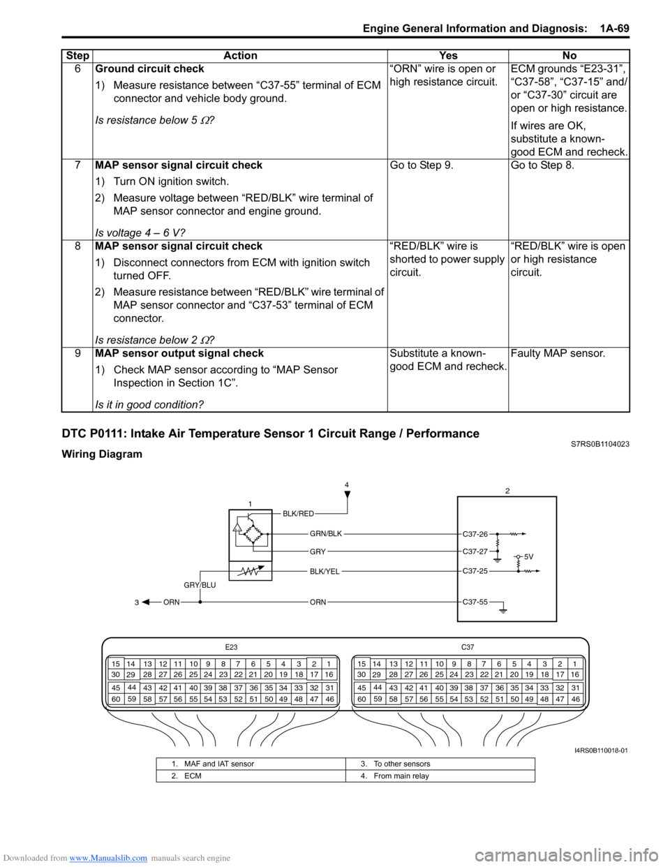
DTC P0111: Intake Air Temperature Sensor 1 Circuit Range / PerformanceS7RS0B1104023
Wiring Diagram6
Ground circuit check
1) Measure resistance between “C37-55” terminal of ECM
connector and vehicle body ground.
Is resistance below 5
Ω? “ORN” wire is open or
high resistance circuit.
ECM grounds “E23-31”,
“C37-58”, “C37-15” and/
or “C37-30” circuit are
open or high resistance.
If wires are OK,
substitute a known-
good ECM and recheck.
7 MAP sensor signal circuit check
1) Turn ON ignition switch.
2) Measure voltage between “RED/BLK” wire terminal of
MAP sensor connector and engine ground.
Is voltage 4 – 6 V? Go to Step 9. Go to Step 8.
8 MAP sensor signal circuit check
1) Disconnect connectors from ECM with ignition switch
turned OFF.
2) Measure resistance between “RED/BLK” wire terminal of MAP sensor connector and “C37-53” terminal of ECM
connector.
Is resistance below 2
Ω? “RED/BLK” wire is
shorted to power supply
circuit.
“RED/BLK” wire is open
or high resistance
circuit.
9 MAP sensor output signal check
1) Check MAP sensor acco rding to “MAP Sensor
Inspection in Section 1C”.
Is it in good condition? Substitute a known-
good ECM and recheck.
Faulty MAP sensor.
Step Action Yes No
E23
C37
34
1819
567
1011
17
20
47 46
495051
2122
52 16
25 9
24
14
29
55
57 54 53
59
60 58 2
262728
15
30
56 4832 31
34353637
40
42 39 38
44
45 43 41 331
1213
238
34
1819
567
1011
17
20
47 46
495051
2122
52 16
25 9
24
14
29
55
57 54 53
59
60 58 2
262728
15
30
56 4832 31
34353637
40
42 39 38
44
45 43 41 331
1213
238
5V
2
BLK/YEL
GRY/BLU
GRY
ORN
1
GRN/BLK
C37-25
C37-55 3 4ORN
C37-26
C37-27
BLK/RED
I4RS0B110018-01
1. MAF and IAT sensor
3. To other sensors
2. ECM 4. From main relay
Page 183 of 1496
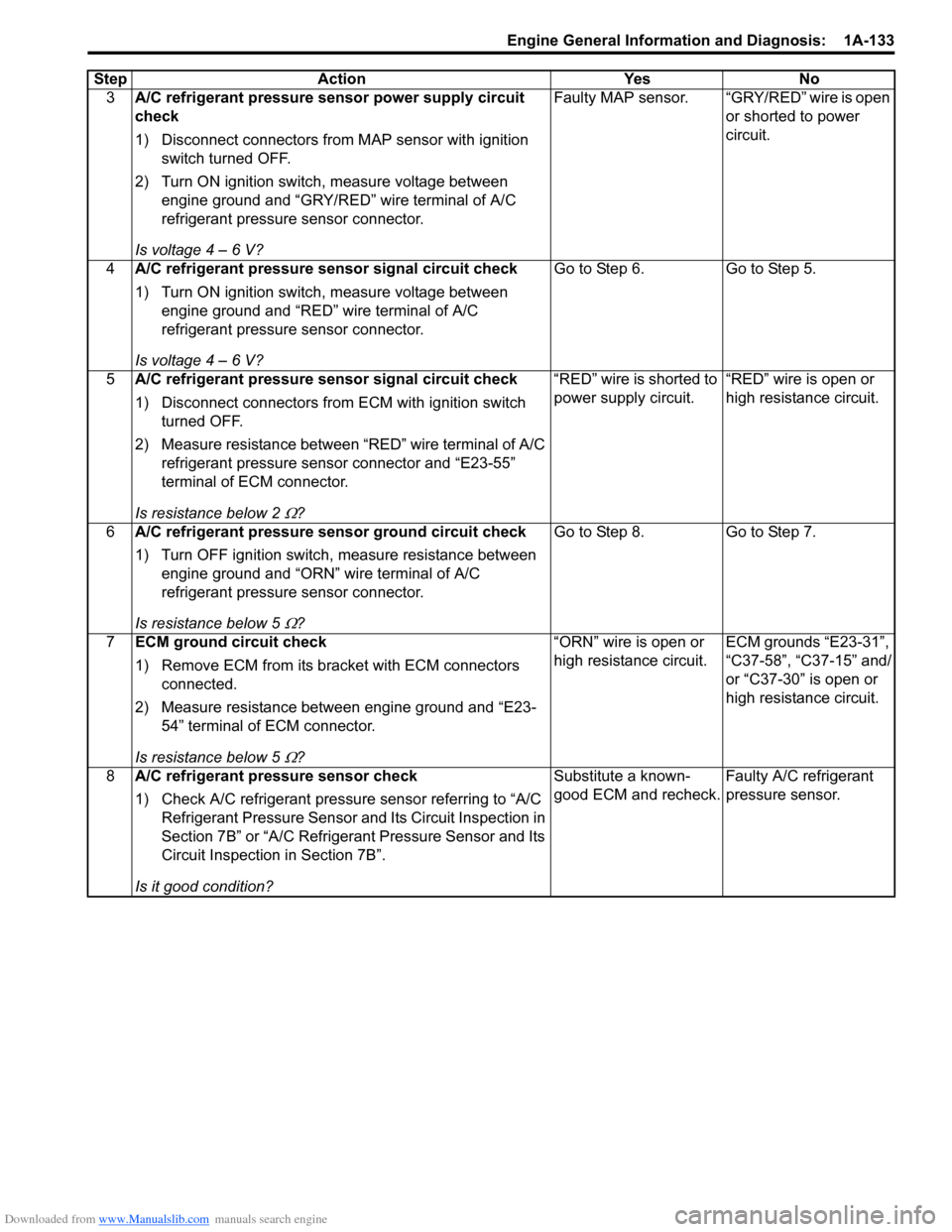
Downloaded from www.Manualslib.com manuals search engine Engine General Information and Diagnosis: 1A-133
3A/C refrigerant pressure sensor power supply circuit
check
1) Disconnect connectors from MAP sensor with ignition
switch turned OFF.
2) Turn ON ignition switch, measure voltage between engine ground and “GRY/RED” wire terminal of A/C
refrigerant pressure sensor connector.
Is voltage 4 – 6 V? Faulty MAP sensor. “GRY/RED” wire is open
or shorted to power
circuit.
4 A/C refrigerant pressure sensor signal circuit check
1) Turn ON ignition switch, measure voltage between
engine ground and “RED” wire terminal of A/C
refrigerant pressure sensor connector.
Is voltage 4 – 6 V? Go to Step 6.
Go to Step 5.
5 A/C refrigerant pressure sensor signal circuit check
1) Disconnect connectors from ECM with ignition switch
turned OFF.
2) Measure resistance between “RED” wire terminal of A/C refrigerant pressure sensor connector and “E23-55”
terminal of ECM connector.
Is resistance below 2
Ω? “RED” wire is shorted to
power supply circuit.
“RED” wire is open or
high resistance circuit.
6 A/C refrigerant pressure sensor ground circuit check
1) Turn OFF ignition switch, measure resistance between
engine ground and “ORN” wire terminal of A/C
refrigerant pressure sensor connector.
Is resistance below 5
Ω? Go to Step 8.
Go to Step 7.
7 ECM ground circuit check
1) Remove ECM from its br acket with ECM connectors
connected.
2) Measure resistance between engine ground and “E23- 54” terminal of ECM connector.
Is resistance below 5
Ω? “ORN” wire is open or
high resistance circuit.
ECM grounds “E23-31”,
“C37-58”, “C37-15” and/
or “C37-30” is open or
high resistance circuit.
8 A/C refrigerant pressure sensor check
1) Check A/C refrigerant pressure sensor referring to “A/C
Refrigerant Pressure Sensor and Its Circuit Inspection in
Section 7B” or “A/C Refrigerant Pressure Sensor and Its
Circuit Inspection in Section 7B”.
Is it good condition? Substitute a known-
good ECM and recheck.
Faulty A/C refrigerant
pressure sensor.
Step Action Yes No
Page 416 of 1496
Downloaded from www.Manualslib.com manuals search engine 1J-6 Charging System:
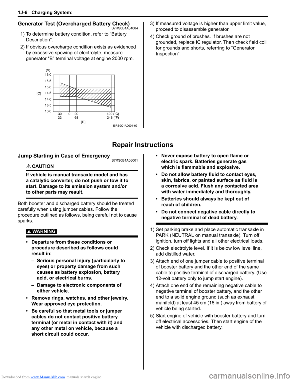
Generator Test (Overcharged Battery Check)S7RS0B1A04004
1) To determine battery condition, refer to “Battery Description”.
2) If obvious overcharge condition exists as evidenced by excessive spewing of electrolyte, measure
generator “B” terminal voltage at engine 2000 rpm. 3) If measured voltage is higher than upper limit value,
proceed to disassemble generator.
4) Check ground of brushes. If brushes are not grounded, replace IC regulator. Then check field coil
for grounds and shorts, referring to “Generator
Inspection”.
Repair Instructions
Jump Starting in Case of EmergencyS7RS0B1A06001
CAUTION!
If vehicle is manual transaxle model and has
a catalytic converter, do not push or tow it to
start. Damage to its emission system and/or
to other parts may result.
Both booster and discharged battery should be treated
carefully when using ju mper cables. Follow the
procedure outlined as follows, being careful not to cause
sparks.
WARNING!
• Departure from these conditions or procedure described as follows could
result in:
– Serious personal injury (particularly to eyes) or property damage from such
causes as battery explosion, battery
acid, or electrical burns.
– Damage to electronic components of either vehicle.
• Remove rings, watches, and other jewelry. Wear approved eye protection.
• Be careful so that metal tools or jumper cables do not contact positive battery
terminal (or metal in contact with it) and
any other metal on vehicle, because a
short circuit could occur. • Never expose battery to open flame or
electric spark. Batteries generate gas
which is flammable and explosive.
• Do not allow battery fluid to contact eyes, skin, fabrics, or painted surface as fluid is
a corrosive acid. Flush any contacted area
with water immediately and thoroughly.
• Batteries should always be kept out of reach of children.
• Do not connect negative cable directly to negative terminal of dead battery.
1) Set parking brake and place automatic transaxle in PARK (NEUTRAL on manual transaxle). Turn off
ignition, turn off lights and all other electrical loads.
2) Check electrolyte level. If it is below low level line, add distilled water.
3) Attach end of one jumper cable to positive terminal of booster battery and the other end of the same
cable to positive terminal of discharged battery. (Use
12-volt battery only to jump start engine).
4) Attach one end of the remaining negative cable to negative terminal of booster battery, and the other
end to a solid engine ground (such as exhaust
manifold) at least 45 cm (18 in.) away from battery of
vehicle being started.
5) Start engine of vehicle with booster battery and turn off electrical accessories. Then start engine of the
vehicle with discharged battery.
16.0
15.5
15.0
14.5
14.0
13.5
13.0 -30 0 20
[C]
[D]
68
22120 (˚C)
248 (˚F)
(V)
I6RS0C1A0001-02
Page 1072 of 1496
Downloaded from www.Manualslib.com manuals search engine 8B-34 Air Bag System:
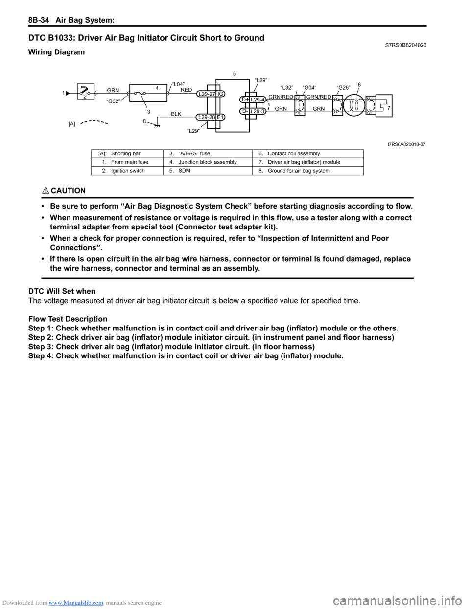
DTC B1033: Driver Air Bag Initiator Circuit Short to GroundS7RS0B8204020
Wiring Diagram
CAUTION!
• Be sure to perform “Air Bag Diagnostic System Check” before starting diagnosis according to flow.
• When measurement of resistance or voltage is required in this flow, use a tester along with a correct terminal adapter from special tool (Connector test adapter kit).
• When a check for proper connection is required, refer to “Inspection of Intermittent and Poor Connections”.
• If there is open circuit in the air bag wire harnes s, connector or terminal is found damaged, replace
the wire harness, connector and terminal as an assembly.
DTC Will Set when
The voltage measured at driver air bag initiator ci rcuit is below a specified value for specified time.
Flow Test Description
Step 1: Check whether malfunction is in contact coil and driver air bag (inflator) module or the others.
Step 2: Check driver air bag (inflator) module initiator circuit. (in instrument panel and floor harness)
Step 3: Check driver air bag (inflator) module initiator circuit. (in floor harness)
Step 4: Check whether malfunction is in contact coil or driver air bag (inflator) module.
1 2
3
GRN
RED
8
BLK
L29-27
L29-28 IG
E1
4
“L29”
“L04”
“G32”
“L29”
L29-4
D+
L29-3
D-GRN
GRN/RED
GRN
GRN/RED 6
57
“G26”
“L32” “G04”
[A]
I7RS0A820010-07
[A]: Shorting bar 3. “A/BAG” fuse 6. Contact coil assembly
1. From main fuse 4. Junction block assembly 7. Driver air bag (inflator) module
2. Ignition switch 5. SDM 8. Ground for air bag system
Page 1088 of 1496
Downloaded from www.Manualslib.com manuals search engine 8B-50 Air Bag System:
NOTE
Upon completion of inspection and repair work, perform the following items.
• Reconnect all air bag system components and ensure all components are properly mounted.
• Clear DTCs referring to “DTC Clearance”, if any.
• Repeat “Air Bag Diagnostic System Check” to confirm that the trouble has been corrected.
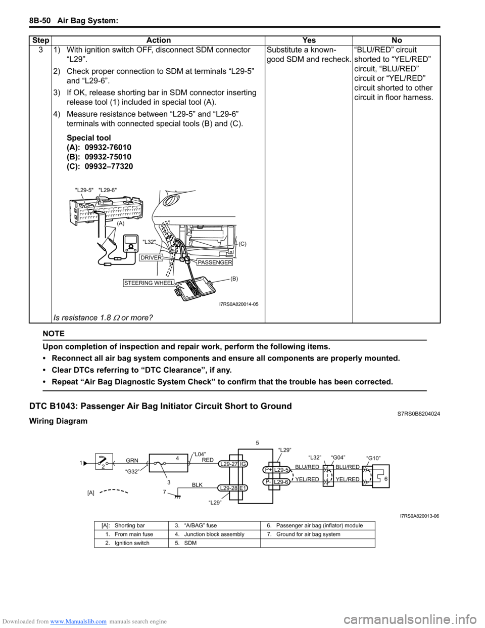
DTC B1043: Passenger Air Bag Initiator Circuit Short to GroundS7RS0B8204024
Wiring Diagram3 1) With ignition switch OFF, disconnect SDM connector
“L29”.
2) Check proper connection to SDM at terminals “L29-5” and “L29-6”.
3) If OK, release shorting bar in SDM connector inserting
release tool (1) included in special tool (A).
4) Measure resistance between “L29-5” and “L29-6” terminals with connected special tools (B) and (C).
Special tool
(A): 09932-76010
(B): 09932-75010
(C): 09932–77320
Is resistance 1.8
Ω or more? Substitute a known-
good SDM and recheck.
“BLU/RED” circuit
shorted to “YEL/RED”
circuit, “BLU/RED”
circuit or “YEL/RED”
circuit shorted to other
circuit in floor harness.
Step Action Yes No
(A)
"L29-6"
"L29-5"
(B) (C)
"L32"STEERING WHEEL
DRIVERPASSENGER
I7RS0A820014-05
1
2
3
GRN
RED
7
BLK
L29-27
L29-28 IG
E1
4
“L29”
“L04”
“G32”
“L29”
L29-5
P+
L29-6
P-YEL/RED
BLU/RED
YEL/RED
BLU/RED
56
“L32” “G04”
“G10”
[A]
I7RS0A820013-06
[A]: Shorting bar
3. “A/BAG” fuse 6. Passenger air bag (inflator) module
1. From main fuse 4. Junction block assembly 7. Ground for air bag system
2. Ignition switch 5. SDM