2008 SUZUKI SWIFT Grounds
[x] Cancel search: GroundsPage 1098 of 1496
Downloaded from www.Manualslib.com manuals search engine 8B-60 Air Bag System:
NOTE
Upon completion of inspection and repair work, perform the following items.
• Reconnect all air bag system components and ensure all components are properly mounted.
• Clear DTCs referring to “DTC Clearance”, if any.
• Repeat “Air Bag Diagnostic System Check” to confirm that the trouble has been corrected.
DTC B1053 / B1057: Driver / Passenger Pretensioner Initiator Circuit Short to GroundS7RS0B8204028
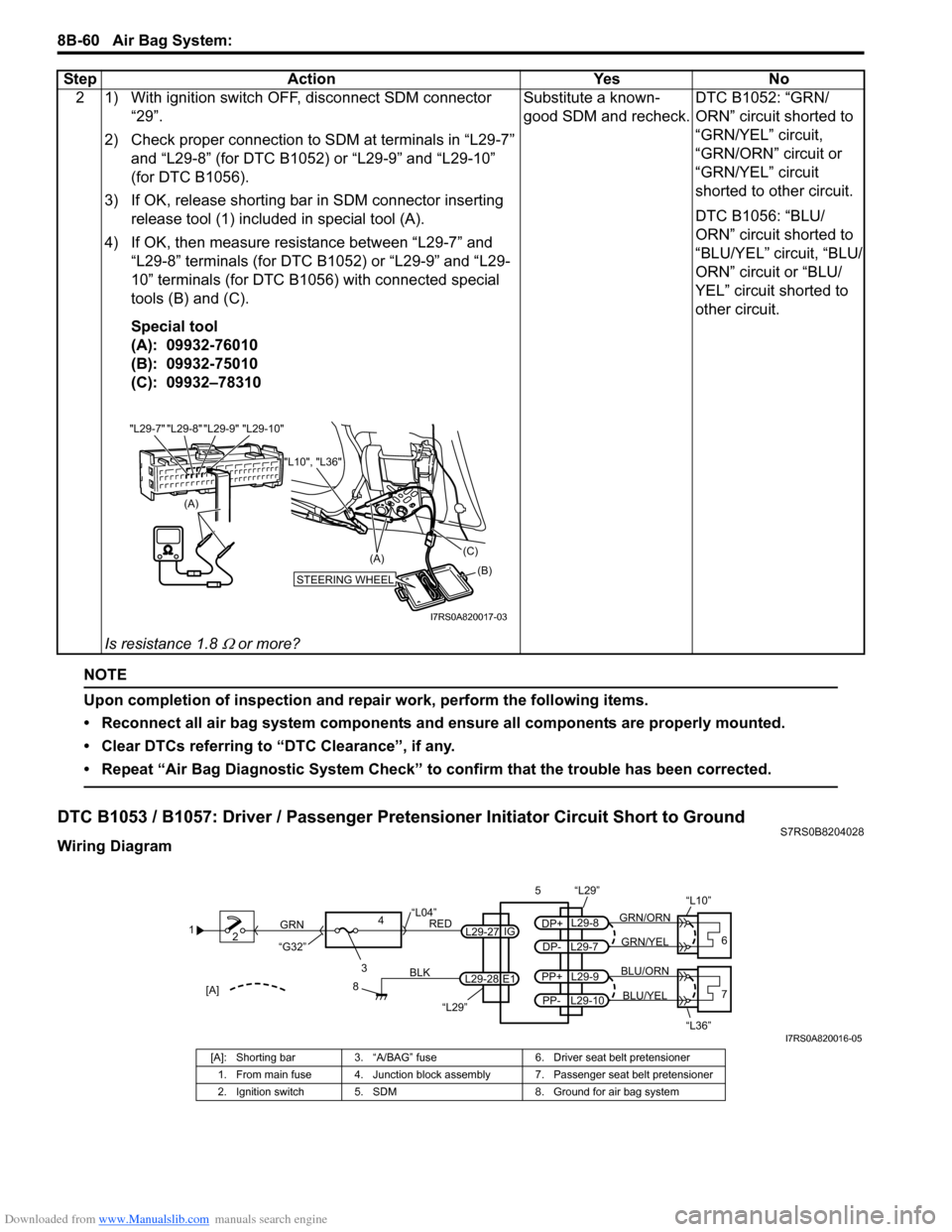
Wiring Diagram2 1) With ignition switch OFF, disconnect SDM connector
“29”.
2) Check proper connection to SDM at terminals in “L29-7” and “L29-8” (for DTC B1052) or “L29-9” and “L29-10”
(for DTC B1056).
3) If OK, release shorting bar in SDM connector inserting
release tool (1) included in special tool (A).
4) If OK, then measure resistance between “L29-7” and “L29-8” terminals (for DTC B1052) or “L29-9” and “L29-
10” terminals (for DTC B1056) with connected special
tools (B) and (C).
Special tool
(A): 09932-76010
(B): 09932-75010
(C): 09932–78310
Is resistance 1.8
Ω or more? Substitute a known-
good SDM and recheck.
DTC B1052: “GRN/
ORN” circuit shorted to
“GRN/YEL” circuit,
“GRN/ORN” circuit or
“GRN/YEL” circuit
shorted to other circuit.
DTC B1056: “BLU/
ORN” circuit shorted to
“BLU/YEL” circuit, “BLU/
ORN” circuit or “BLU/
YEL” circuit shorted to
other circuit.
Step Action Yes No
(A)
"L29-8" "L29-9" "L29-10"
"L29-7"
STEERING WHEEL(B)
(C)
(A)
"L10", "L36"
I7RS0A820017-03
1
2
3
GRN
RED
8
BLK
L29-27
L29-28 IG
E1
4
“L29”
“L04”
“G32”
“L29”
L29-8
DP+
L29-7
DP-GRN/YEL
GRN/ORN
56
“L10”
L29-9
PP+
L29-10
PP-BLU/YEL
BLU/ORN7
“L36”[A]
I7RS0A820016-05
[A]: Shorting bar 3. “A/BAG” fuse 6. Driver seat belt pretensioner
1. From main fuse 4. Junction block assembly 7. Passenger seat belt pretensioner
2. Ignition switch 5. SDM 8. Ground for air bag system
Page 1108 of 1496
Downloaded from www.Manualslib.com manuals search engine 8B-70 Air Bag System:
NOTE
Upon completion of inspection and repair work, perform the following items.
• Reconnect all air bag system components, ensure all components are properly mounted.
• Clear DTCs referring to “DTC Clearance”, if any.
• Repeat “Air Bag Diagnostic System Check” to confirm that the trouble has been corrected.
DTC B1063 / B1067: Driver / Passenger Side-Air Bag Initiator Circuit Short to GroundS7RS0B8204032
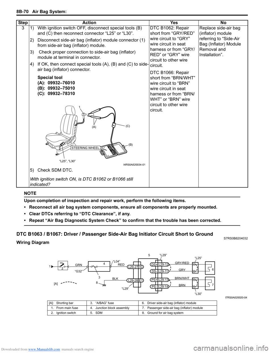
Wiring Diagram3 1) With ignition switch OFF, disconnect special tools (B)
and (C) then reconnect connector “L25” or “L30”.
2) Disconnect side-air bag (inflator) module connector (1) from side-air bag (inflator) module.
3) Check proper connection to side-air bag (inflator) module at terminal in connector.
4) If OK, then connect special tools (A), (B) and (C) to side- air bag (inflator) connector.
Special tool
(A): 09932–76010
(B): 09932–75010
(C): 09932–78310
5) Check SDM DTC.
With ignition switch ON, is DTC B1062 or B1066 still
indicated? DTC B1062: Repair
short from “GRY/RED”
wire circuit to “GRY”
wire circuit in seat
harness or from “GRY/
RED” or “GRY” wire
circuit to other wire
circuit.
DTC B1066: Repair
short from “BRN/WHT”
wire circuit to “BRN”
wire circuit in seat
harness or from “BRN/
WHT” or “BRN” wire
circuit to other wire
circuit.
Replace side-air bag
(inflator) module
referring to “Side-Air
Bag (Inflator) Module
Removal and
Installation”.
Step Action Yes No
1
“L25”, “L30”
STEERING WHEEL(B)
(C)
(A)
I4RS0A820034-01
1
2
3
GRN
RED
8
BLK
L29-27
L29-28 IG
E1
4
“L29”
“L04”
“G32”
“L29”
L29-12
DS+
L29-11
DS-GRY
GRY/RED
56
“L25”
L29-13
PS+
L29-14
PS-BRN
BRN/WHT7
“L30”[A]
I7RS0A820020-04
[A]: Shorting bar 3. “A/BAG” fuse 6. Driver side-air bag (inflator) module
1. From main fuse 4. Junction block assembly 7. Passenger side-air bag (inflator) module
2. Ignition switch 5. SDM 8. Ground for air bag system
Page 1114 of 1496
Downloaded from www.Manualslib.com manuals search engine 8B-76 Air Bag System:
NOTE
Upon completion of inspection and repair work, perform the following items.
• Reconnect all air bag system components, ensure all components are properly mounted.
• Clear DTCs referring to “DTC Clearance”, if any.
• Repeat “Air Bag Diagnostic System Check” to confirm that the trouble has been corrected.
DTC B1071: Forward-Sensor Performance ProblemS7RS0B8204034
DTC Will Set when
SDM receives internal fault signal or wrong ID (Part No.) signal from forward-sensor.
DTC Troubleshooting1) Turn ignition switch OFF.
2) Replace forward-sensor referring to “Forward-Sensor Removal and Installation”.
3) Repeat “Air Bag Diagnostic System Check”.
DTC B1072: Forward-Sensor Communication ErrorS7RS0B8204035
DTC Will Set when
Forward-sensor abnormal signal is detected by SDM.
DTC Troubleshooting
1) Turn ignition switch OFF.
2) Replace forward-sensor referring to “Forward-Sensor Removal and Installation”.
3) Repeat “Air Bag Diagnostic System Check”.
NOTE
Upon completion of inspection and repair work, perform the following items.
• Reconnect all air bag system components and ensure all components are properly mounted.
• Clear DTCs referring to “DTC Clearance”, if any.
• Repeat “Air Bag Diagnostic System Check” to confirm that the trouble has been corrected.
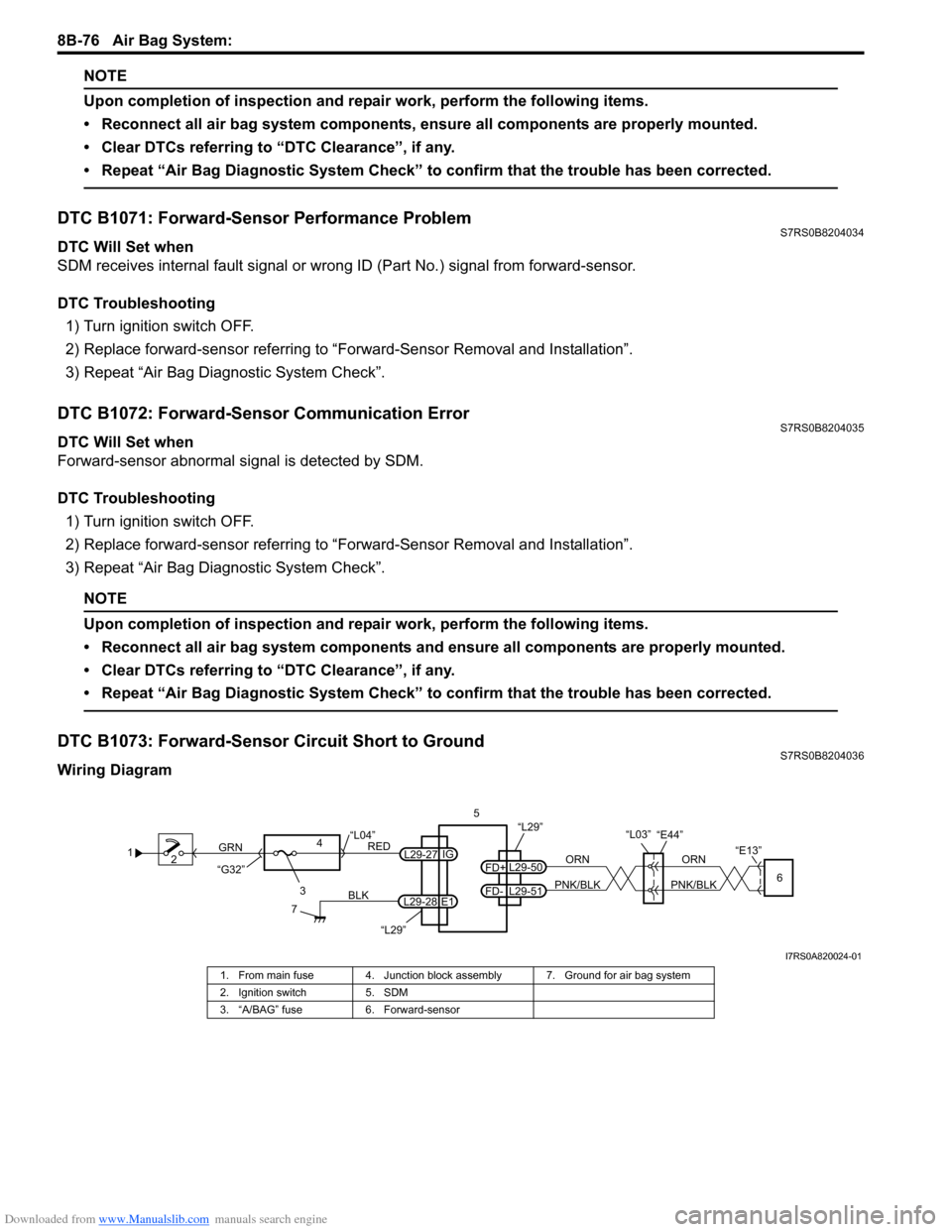
DTC B1073: Forward-Sensor Circuit Short to GroundS7RS0B8204036
Wiring Diagram
1 2
3
GRN
RED
7
BLK
L29-27
L29-28 IG
E1
4
“L29”
“L04”
“G32”
“L29”5
ORN
PNK/BLK
ORN
PNK/BLKL29-50
FD+
L29-51
FD-6
“E13”
“L03”“E44”
I7RS0A820024-01
1. From main fuse 4. Junction block assembly 7. Ground for air bag system
2. Ignition switch 5. SDM
3. “A/BAG” fuse 6. Forward-sensor
Page 1118 of 1496
Downloaded from www.Manualslib.com manuals search engine 8B-80 Air Bag System:
DTC B1081 / B1091: Driver / Passenger Side-Sensor Performance ProblemS7RS0B8204038
DTC Will Set when
SDM receives internal fault signal from side-sensor.
DTC Troubleshooting1) Turn ignition switch OFF.
2) Replace driver or passenger side-sensor referr ing to “Side-Sensor Removal and Installation”.
3) Repeat “Air Bag Diagnostic System Check”.
DTC B1082 / B1092: Driver / Passenger Side-Sensor Communication ErrorS7RS0B8204039
DTC Will Set when
Side-sensor abnormal signal is detected by SDM.
DTC Troubleshooting
1) Turn ignition switch OFF.
2) Replace driver or passenger side-sensor referr ing to “Side-Sensor Removal and Installation”.
3) Repeat “Air Bag Diagnostic System Check”.
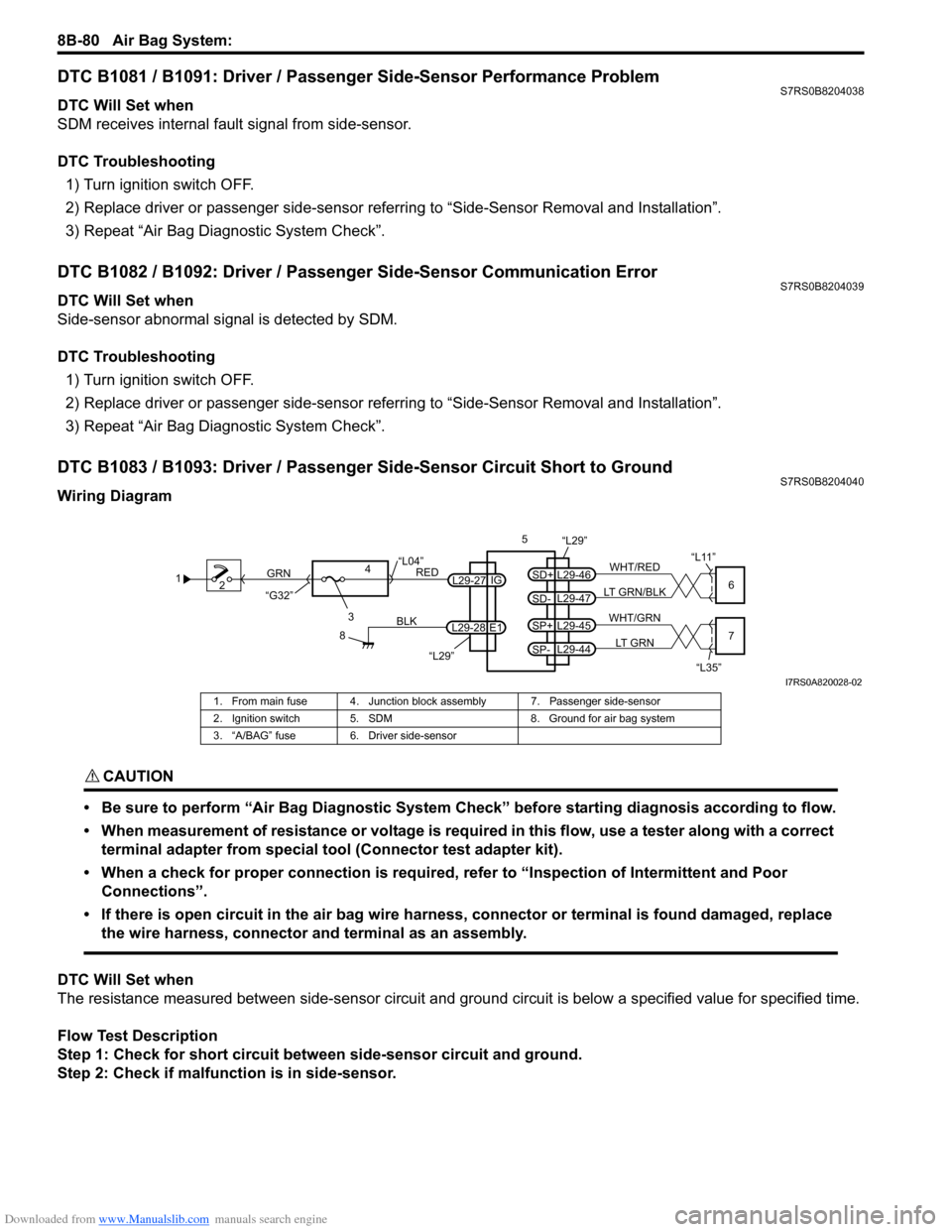
DTC B1083 / B1093: Driver / Passenger Side-Sensor Circuit Short to GroundS7RS0B8204040
Wiring Diagram
CAUTION!
• Be sure to perform “Air Bag Diagnostic System Check” before starting diagnosis according to flow.
• When measurement of resistance or voltage is required in this flow, use a tester along with a correct terminal adapter from special tool (Connector test adapter kit).
• When a check for proper connection is required, refer to “Inspection of Intermittent and Poor Connections”.
• If there is open circuit in the air bag wire harnes s, connector or terminal is found damaged, replace
the wire harness, connector and terminal as an assembly.
DTC Will Set when
The resistance measured between side-sen sor circuit and ground circuit is below a specified value for specified time.
Flow Test Description
Step 1: Check for short circuit between side-sensor circuit and ground.
Step 2: Check if malfunction is in side-sensor.
1 2
3
GRN
RED
8
BLK
L29-27
L29-28 IG
E1
4
“L29”
“L04”
“G32”
“L29”5
WHT/RED
LT GRN/BLKL29-46
SD+
L29-47
SD-6
“L11”
WHT/GRN
LT GRNL29-45
SP+
L29-44
SP-7
“L35”
I7RS0A820028-02
1. From main fuse 4. Junction blo ck assembly 7. Passenger side-sensor
2. Ignition switch 5. SDM 8. Ground for air bag system
3. “A/BAG” fuse 6. Driver side-sensor
Page 1126 of 1496
Downloaded from www.Manualslib.com manuals search engine 8B-88 Air Bag System:
NOTE
Upon completion of inspection and repair work, perform the following items.
• Reconnect all air bag system components, ensure all components are properly mounted.
• Clear DTCs referring to “DTC Clearance”, if any.
• Repeat “Air Bag Diagnostic System Check” to confirm that the trouble has been corrected.
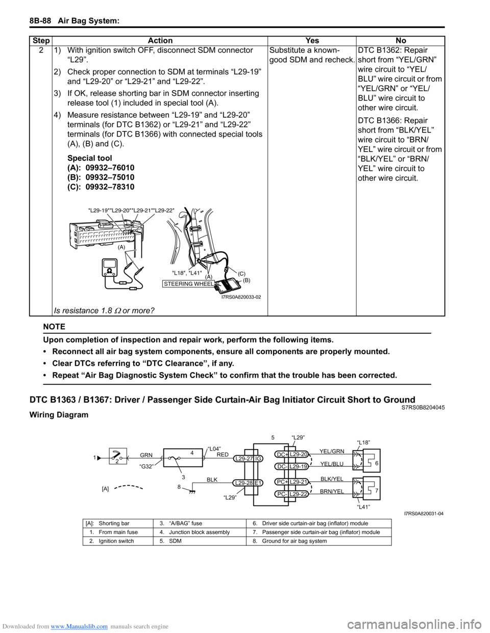
DTC B1363 / B1367: Driver / Passenger Side Curtain-Air Bag Initiator Circuit Short to GroundS7RS0B8204045
Wiring Diagram2 1) With ignition switch OFF, disconnect SDM connector
“L29”.
2) Check proper connection to SDM at terminals “L29-19” and “L29-20” or “L29-21” and “L29-22”.
3) If OK, release shorting bar in SDM connector inserting
release tool (1) included in special tool (A).
4) Measure resistance between “L29-19” and “L29-20” terminals (for DTC B1362) or “L29-21” and “L29-22”
terminals (for DTC B1366) with connected special tools
(A), (B) and (C).
Special tool
(A): 09932–76010
(B): 09932–75010
(C): 09932–78310
Is resistance 1.8
Ω or more? Substitute a known-
good SDM and recheck.
DTC B1362: Repair
short from “YEL/GRN”
wire circuit to “YEL/
BLU” wire circuit or from
“YEL/GRN” or “YEL/
BLU” wire circuit to
other wire circuit.
DTC B1366: Repair
short from “BLK/YEL”
wire circuit to “BRN/
YEL” wire circuit or from
“BLK/YEL” or “BRN/
YEL” wire circuit to
other wire circuit.
Step Action Yes No
(A)
"L29-20""L29-21""L29-22"
"L29-19"
STEERING WHEEL(B)
(C)
(A)
"L18", "L41"
I7RS0A820033-02
1
2
3
GRN
RED
8
BLK
L29-27
L29-28 IG
E1
4
“L29”
“L04”
“G32”
“L29”
L29-20
DC+
L29-19
DC-YEL/BLU
YEL/GRN
56
“L18”
L29-21
PC+
L29-22
PC-BRN/YEL BLK/YEL7
“L41”[A]
I7RS0A820031-04
[A]: Shorting bar 3. “A/BAG” fuse 6. Driver side curtain-air bag (inflator) module
1. From main fuse 4. Junction block assembly 7. Passenger side curtain-air bag (inflator) module
2. Ignition switch 5. SDM 8. Ground for air bag system
Page 1417 of 1496
Downloaded from www.Manualslib.com manuals search engine Body Electrical Control System: 10B-14
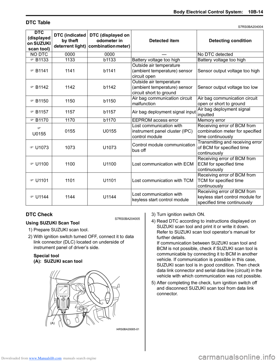
DTC TableS7RS0BA204004
DTC CheckS7RS0BA204005
Using SUZUKI Scan Tool1) Prepare SUZUKI scan tool.
2) With ignition switch turned OFF, connect it to data link connector (DLC) located on underside of
instrument panel of driver’s side.
Special tool
(A): SUZUKI scan tool 3) Turn ignition switch ON.
4) Read DTC according to
instructions displayed on
SUZUKI scan tool and print it or write it down.
Refer to SUZUKI scan tool operator’s manual for
further details.
If communication between SUZUKI scan tool and
BCM is not possible, check if SUZUKI scan tool is
communicable by connecting it to BCM in another
vehicle. If communication is possible in this case,
SUZUKI scan tool is in good condition. Then check
data link connector and serial data line (circuit) in the
vehicle with which communica tion was not possible.
5) After completing the check, turn ignition switch off and disconnect SUZUKI scan tool from data link
connector.
DTC
(displayed
on SUZUKI scan tool) DTC (indicated
by theft
deterrent light) DTC (displayed on
odometer in
combination meter) Detected item Detecting condition
NO DTC 0000 0000 — No DTC detected
�) B1133 1133 b1133 Battery voltage too high Battery voltage too high
�) B1141 1141 b1141 Outside air temperature
(ambient temperature) sensor
circuit openSensor output voltage too high
�) B1142 1142 b1142 Outside air temperature
(ambient temperature) sensor
circuit short to groundSensor output voltage too low
�) B1150 1150 b1150 Air bag communication circuit
malfunctionAir bag communication circuit
open or short to ground
�) B1157 1157 b1157 Air bag deployment signal input Air bag deployment signal
inputted
�) B1170 1170 b1170 EEPROM access error Memory error
�)
U0155 0155 U0155 Lost communication with
instrument panel cluster (IPC)
control moduleReceiving error of BCM from
combination mete
r for specified
time continuously
�) U1073 1073 U1073 Control module communication
bus offTransmitting and receiving error
of BCM for specified time
continuously
�) U1100 1100 U1100 Lost communication with ECM Receiving error of BCM from
ECM for specified time
continuously
�) U1101 1101 U1101 Lost communication with TCM Receiving error of BCM from
TCM for specified time
continuously
�) U1144 1144 U1144 Lost communication with
keyless start control moduleReceiving error of BCM from
keyless start control module for
specified time continuously
(A)
I4RS0BA20005-01