2008 SUZUKI SWIFT Oscilloscope
[x] Cancel search: OscilloscopePage 170 of 1496
Downloaded from www.Manualslib.com manuals search engine 1A-120 Engine General Information and Diagnosis:
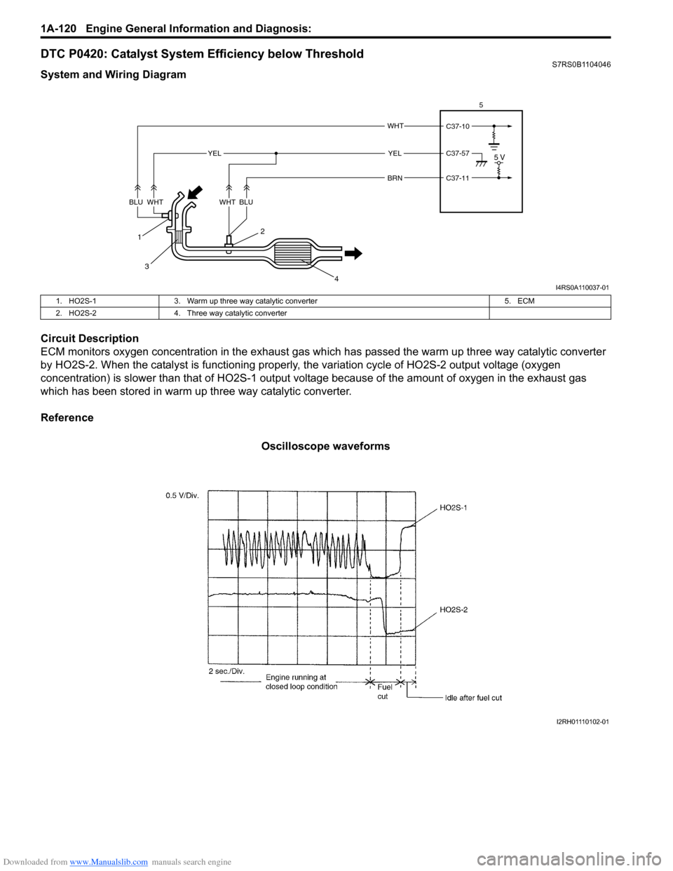
DTC P0420: Catalyst System Efficiency below ThresholdS7RS0B1104046
System and Wiring Diagram
Circuit Description
ECM monitors oxygen concentration in the exhaust gas which has passed the warm up three way catalytic converter
by HO2S-2. When the catalyst is functioning properly, the variation cycle of HO2S-2 output voltage (oxygen
concentration) is slower than that of HO2S-1 output voltage because of the amount of oxygen in the exhaust gas
which has been stored in warm up three way catalytic converter.
Reference
Oscilloscope waveforms
C37-11
C37-10
C37-57
WHT
BRN
1
3 2
4
5 VYELYEL
BLUWHTBLUWHT 5
I4RS0A110037-01
1. HO2S-1
3. Warm up three way catalytic converter 5. ECM
2. HO2S-2 4. Three way catalytic converter
I2RH01110102-01
Page 225 of 1496
Downloaded from www.Manualslib.com manuals search engine Engine General Information and Diagnosis: 1A-175
Inspection of ECM and Its CircuitsS7RS0B1104079
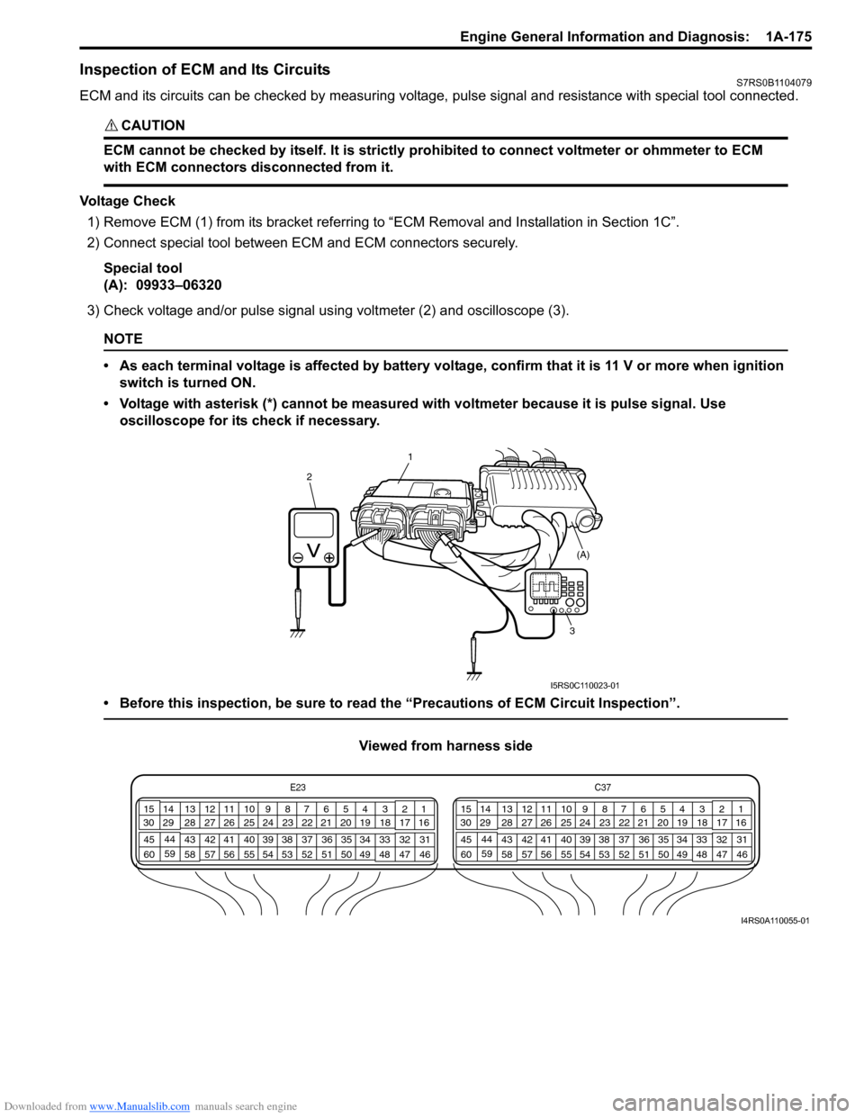
ECM and its circuits can be checked by measuring voltage, pulse signal and resistance with special tool connected.
CAUTION!
ECM cannot be checked by itself. It is strictly prohibited to connect voltmeter or ohmmeter to ECM
with ECM connectors disconnected from it.
Voltage Check
1) Remove ECM (1) from its bracke t referring to “ECM Removal and Installation in Section 1C”.
2) Connect special tool between EC M and ECM connectors securely.
Special tool
(A): 09933–06320
3) Check voltage and/or pulse signal us ing voltmeter (2) and oscilloscope (3).
NOTE
• As each terminal voltage is affected by battery voltag e, confirm that it is 11 V or more when ignition
switch is turned ON.
• Voltage with asterisk (*) cannot be measured with voltmeter because it is pulse signal. Use oscilloscope for its check if necessary.
• Before this inspection, be sure to read the “Precautions of ECM Circuit Inspection”.
Viewed from harness side
1
2
3 (A)
I5RS0C110023-01
E23
C37
34
1819
567
1011
17
20
47 46
495051
2122
52 16
25 9
24
14
29
55
57 54 53
59
60 58 2
262728
15
30
56 4832 31
34353637
40
42 39 38
44
45 43 41 331
1213
238
34
1819
567
1011
17
20
47 46
495051
2122
52 16
25 9
24
14
29
55
57 54 53
59
60 58 2
262728
15
30
56 4832 31
34353637
40
42 39 38
44
45 43 41 331
1213
238
I4RS0A110055-01
Page 234 of 1496
Downloaded from www.Manualslib.com manuals search engine 1A-184 Engine General Information and Diagnosis:
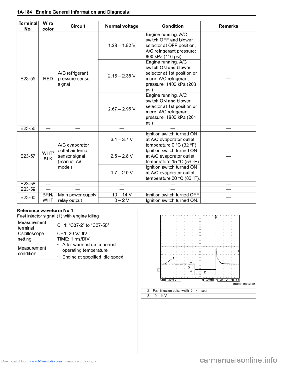
Reference waveform No.1
Fuel injector signal (1) with engine idling
E23-55 RED
A/C refrigerant
pressure sensor
signal 1.38 – 1.52 V
Engine running, A/C
switch OFF and blower
selector at OFF position,
A/C refrigerant pressure:
800 kPa (116 psi)
—
2.15 – 2.38 V Engine running, A/C
switch ON and blower
selector at 1st position or
more, A/C refrigerant
pressure: 1400 kPa (203
psi)
2.67 – 2.95 V Engine running, A/C
switch ON and blower
selector at 1st position or
more, A/C refrigerant
pressure: 1800 kPa (261
psi)
E23-56 — — — — —
E23-57 WHT/
BLK A/C evaporator
outlet air temp.
sensor signal
(manual A/C
model) 3.4 – 3.7 V
Ignition switch turned ON
at A/C evaporator outlet
temperature 0
°C (32 °F).
—
2.5 – 2.8 V Ignition switch turned ON
at A/C evaporator outlet
temperature 15
°C (59 °F).
1.7 – 2.0 V Ignition switch turned ON
at A/C evaporator outlet
temperature 30
°C (86 °F).
E23-58 — — — — —
E23-59 — — — — —
E23-60 BRN/
WHT Main power supply
relay output 10 – 14 V Ignition switch turned OFF.
—
0 – 2 V Ignition switch turned ON.
Terminal
No. Wire
color Circuit Normal voltage Condition Remarks
Measurement
terminal CH1: “C37-2” to “C37-58”
Oscilloscope
setting CH1: 20 V/DIV
TIME: 1 ms/DIV
Measurement
condition • After warmed up to normal
operating temperature
• Engine at specified idle speed
2. Fuel injection pulse width: 2 – 4 msec.
3. 10 – 14 V
I4RS0B110050-01
Page 235 of 1496
Downloaded from www.Manualslib.com manuals search engine Engine General Information and Diagnosis: 1A-185
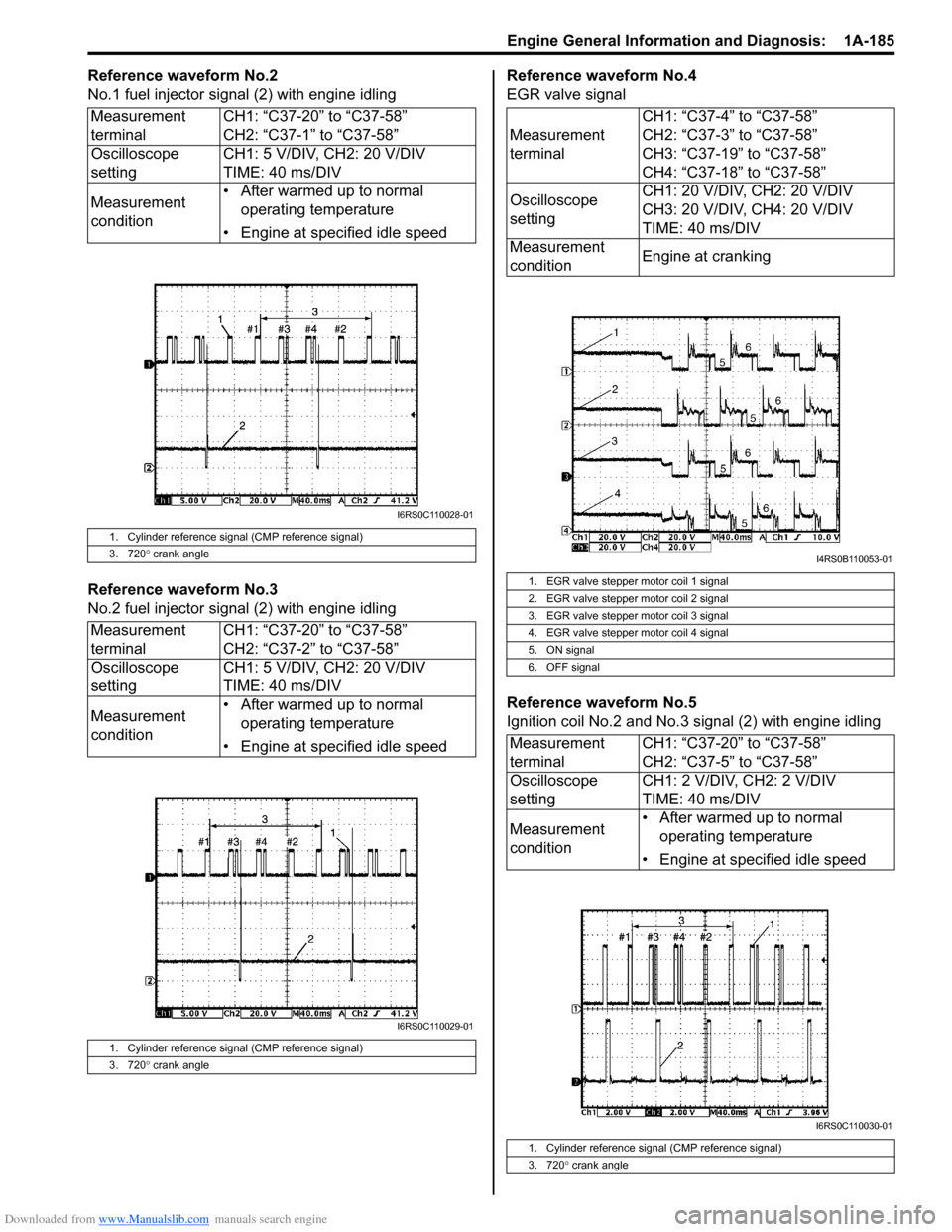
Reference waveform No.2
No.1 fuel injector signal (2) with engine idling
Reference waveform No.3
No.2 fuel injector sig nal (2) with engine idling Reference waveform No.4
EGR valve signal
Reference waveform No.5
Ignition coil No.2 and No.3 signal (2) with engine idling
Measurement
terminal
CH1: “C37-20” to “C37-58”
CH2: “C37-1” to “C37-58”
Oscilloscope
setting CH1: 5 V/DIV, CH2: 20 V/DIV
TIME: 40 ms/DIV
Measurement
condition • After warmed up to normal
operating temperature
• Engine at specified idle speed
1. Cylinder reference signal (CMP reference signal)
3. 720 ° crank angle
Measurement
terminal CH1: “C37-20” to “C37-58”
CH2: “C37-2” to “C37-58”
Oscilloscope
setting CH1: 5 V/DIV, CH2: 20 V/DIV
TIME: 40 ms/DIV
Measurement
condition • After warmed up to normal
operating temperature
• Engine at specified idle speed
1. Cylinder reference signal (CMP reference signal)
3. 720 ° crank angle
I6RS0C110028-01
I6RS0C110029-01
Measurement
terminal CH1: “C37-4” to “C37-58”
CH2: “C37-3” to “C37-58”
CH3: “C37-19” to “C37-58”
CH4: “C37-18” to “C37-58”
Oscilloscope
setting CH1: 20 V/DIV, CH2: 20 V/DIV
CH3: 20 V/DIV, CH4: 20 V/DIV
TIME: 40 ms/DIV
Measurement
condition Engine at cranking
1. EGR valve stepper motor coil 1 signal
2. EGR valve stepper motor coil 2 signal
3. EGR valve stepper motor coil 3 signal
4. EGR valve stepper motor coil 4 signal
5. ON signal
6. OFF signal
Measurement
terminalCH1: “C37-20” to “C37-58”
CH2: “C37-5” to “C37-58”
Oscilloscope
setting CH1: 2 V/DIV, CH2: 2 V/DIV
TIME: 40 ms/DIV
Measurement
condition • After warmed up to normal
operating temperature
• Engine at specified idle speed
1. Cylinder reference signal (CMP reference signal)
3. 720 ° crank angle
I4RS0B110053-01
I6RS0C110030-01
Page 236 of 1496
Downloaded from www.Manualslib.com manuals search engine 1A-186 Engine General Information and Diagnosis:
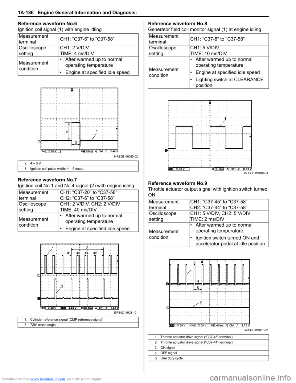
Reference waveform No.6
Ignition coil signal (1) with engine idling
Reference waveform No.7
Ignition coil No.1 and No.4 signal (2) with engine idlingReference waveform No.8
Generator field coil monitor signal (1) at engine idling
Reference waveform No.9
Throttle actuator output signal with ignition switch turned
ON
Measurement
terminal
CH1: “C37-6” to “C37-58”
Oscilloscope
setting CH1: 2 V/DIV
TIME: 4 ms/DIV
Measurement
condition • After warmed up to normal
operating temperature
• Engine at specified idle speed
2. 4 – 6 V
3. Ignition coil pulse width: 4 – 5 msec.
Measurement
terminal CH1: “C37-20” to “C37-58”
CH2: “C37-6” to “C37-58”
Oscilloscope
setting CH1: 2 V/DIV, CH2: 2 V/DIV
TIME: 40 ms/DIV
Measurement
condition • After warmed up to normal
operating temperature
• Engine at specified idle speed
1. Cylinder reference signal (CMP reference signal)
3. 720 ° crank angle
I4RS0B110055-02
I6RS0C110031-01
Measurement
terminal CH1: “C37-8” to “C37-58”
Oscilloscope
setting CH1: 5 V/DIV
TIME: 10 ms/DIV
Measurement
condition • After warmed up to normal
operating temperature
• Engine at specified idle speed
• Lighting switch at CLEARANCE position
Measurement
terminal CH1: “C37-45” to “C37-58”
CH2: “C37-44” to “C37-58”
Oscilloscope
setting CH1: 5 V/DIV, CH2: 5 V/DIV
TIME: 2 ms/DIV
Measurement
condition • After warmed up to normal
operating temperature
• Ignition switch turned ON and accelerator pedal at idle position
1. Throttle actuator drive signal (“C37-45” terminal)
2. Throttle actuator drive signal (“C37-44” terminal)
3. ON signal
4. OFF signal
5. One duty cycle
I5RS0C110016-01
I4RS0B110081-02
Page 237 of 1496
Downloaded from www.Manualslib.com manuals search engine Engine General Information and Diagnosis: 1A-187
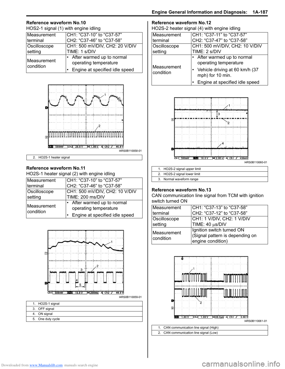
Reference waveform No.10
HOS2-1 signal (1) with engine idling
Reference waveform No.11
HO2S-1 heater signal (2) with engine idlingReference waveform No.12
HO2S-2 heater signal (4) with engine idling
Reference waveform No.13
CAN communication line signal from TCM with ignition
switch turned ON
Measurement
terminal
CH1: “C37-10” to “C37-57”
CH2: “C37-46” to “C37-58”
Oscilloscope
setting CH1: 500 mV/DIV, CH2: 20 V/DIV
TIME: 1 s/DIV
Measurement
condition • After warmed up to normal
operating temperature
• Engine at specified idle speed
2. HO2S-1 heater signal
Measurement
terminal CH1: “C37-10” to “C37-57”
CH2: “C37-46” to “C37-58”
Oscilloscope
setting CH1: 500 mV/DIV, CH2: 10 V/DIV
TIME: 200 ms/DIV
Measurement
condition • After warmed up to normal
operating temperature
• Engine at specified idle speed
1. HO2S-1 signal
3. OFF signal
4. ON signal
5. One duty cycle
I4RS0B110058-01
I4RS0B110059-01
Measurement
terminal CH1: “C37-11” to “C37-57”
CH2: “C37-47” to “C37-58”
Oscilloscope
setting CH1: 500 mV/DIV, CH2: 10 V/DIV
TIME: 2 s/DIV
Measurement
condition • After warmed up to normal
operating temperature
• Vehicle driving at 60 km/h (37 mph) for 10 min.
• Engine at specified idle speed
1. HO2S-2 signal upper limit
2. HO2S-2 signal lower limit
3. Normal waveform range
Measurement
terminal CH1: “C37-13” to “C37-58”
CH2: “C37-12” to “C37-58”
Oscilloscope
setting CH1: 1 V/DIV, CH2: 1 V/DIV
TIME: 40
µs/DIV
Measurement
condition Ignition switch turned ON
(Signal pattern is depending on
engine condition)
1. CAN communication line signal (High)
2. CAN communication line signal (Low)
I4RS0B110060-01
I4RS0B110061-01
Page 238 of 1496
Downloaded from www.Manualslib.com manuals search engine 1A-188 Engine General Information and Diagnosis:
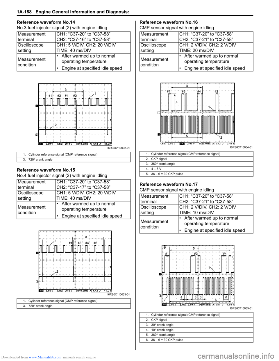
Reference waveform No.14
No.3 fuel injector signal (2) with engine idling
Reference waveform No.15
No.4 fuel injector sig nal (2) with engine idling Reference waveform No.16
CMP sensor signal with engine idling
Reference waveform No.17
CMP sensor signal with engine idling
Measurement
terminal
CH1: “C37-20” to “C37-58”
CH2: “C37-16” to “C37-58”
Oscilloscope
setting CH1: 5 V/DIV, CH2: 20 V/DIV
TIME: 40 ms/DIV
Measurement
condition • After warmed up to normal
operating temperature
• Engine at specified idle speed
1. Cylinder reference signal (CMP reference signal)
3. 720 ° crank angle
Measurement
terminal CH1: “C37-20” to “C37-58”
CH2: “C37-17” to “C37-58”
Oscilloscope
setting CH1: 5 V/DIV, CH2: 20 V/DIV
TIME: 40 ms/DIV
Measurement
condition • After warmed up to normal
operating temperature
• Engine at specified idle speed
1. Cylinder reference signal (CMP reference signal)
3. 720 ° crank angle
I6RS0C110032-01
I6RS0C110033-01
Measurement
terminal CH1: “C37-20” to “C37-58”
CH2: “C37-21” to “C37-58”
Oscilloscope
setting CH1: 2 V/DIV, CH2: 2 V/DIV
TIME: 20 ms/DIV
Measurement
condition • After warmed up to normal
operating temperature
• Engine at specified idle speed
1. Cylinder reference signal (CMP reference signal)
2. CKP signal
3. 360 ° crank angle
4. 4 – 5 V
5. 36 – 6 = 30 CKP pulse
Measurement
terminal CH1: “C37-20” to “C37-58”
CH2: “C37-21” to “C37-58”
Oscilloscope
setting CH1: 2 V/DIV, CH2: 2 V/DIV
TIME: 10 ms/DIV
Measurement
condition • After warmed up to normal
operating temperature
• Engine at specified idle speed
1. Cylinder reference signal (CMP reference signal)
2. CKP signal
3. 30 ° crank angle
4. 10 ° crank angle
5. 360 ° crank angle
6. 36 – 6 = 30 CKP pulse
I6RS0C110034-01
I6RS0C110035-01
Page 239 of 1496
Downloaded from www.Manualslib.com manuals search engine Engine General Information and Diagnosis: 1A-189
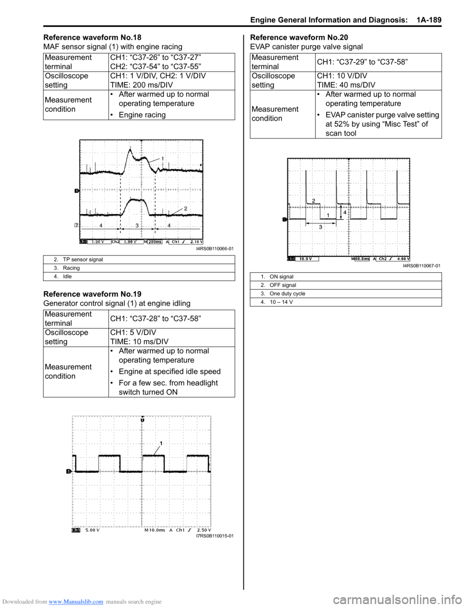
Reference waveform No.18
MAF sensor signal (1) with engine racing
Reference waveform No.19
Generator control signal (1) at engine idlingReference waveform No.20
EVAP canister purge valve signal
Measurement
terminal CH1: “C37-26” to “C37-27”
CH2: “C37-54” to “C37-55”
Oscilloscope
setting CH1: 1 V/DIV, CH2: 1 V/DIV
TIME: 200 ms/DIV
Measurement
condition • After warmed up to normal
operating temperature
• Engine racing
2. TP sensor signal
3. Racing
4. Idle
Measurement
terminal CH1: “C37-28” to “C37-58”
Oscilloscope
setting CH1: 5 V/DIV
TIME: 10 ms/DIV
Measurement
condition • After warmed up to normal
operating temperature
• Engine at specified idle speed
• For a few sec. from headlight switch turned ON
I4RS0B110066-01
I7RS0B110015-01
Measurement
terminal CH1: “C37-29” to “C37-58”
Oscilloscope
setting CH1: 10 V/DIV
TIME: 40 ms/DIV
Measurement
condition • After warmed up to normal
operating temperature
• EVAP canister purge valve setting at 52% by using “Misc Test” of
scan tool
1. ON signal
2. OFF signal
3. One duty cycle
4. 10 – 14 V
I4RS0B110067-01