2008 SUZUKI SWIFT Oscilloscope
[x] Cancel search: OscilloscopePage 1434 of 1496
Downloaded from www.Manualslib.com manuals search engine 10B-31 Body Electrical Control System:
Inspection of BCM and its CircuitsS7RS0BA204018
BCM and its circuits can be checked at BCM wiring couplers by measuring voltage and resistance.
CAUTION!
BCM cannot be checked by itself. It is strictly prohibited to connect voltmeter or ohmmeter to BCM
with couplers disconnected from it.
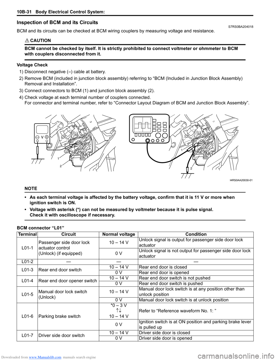
Voltage Check1) Disconnect negative (–) cable at battery.
2) Remove BCM (included in junction block assembly) refe rring to “BCM (Included in Junction Block Assembly)
Removal and Installation”.
3) Connect connectors to BCM (1) and junction block assembly (2).
4) Check voltage at each terminal number of couplers connected. For connector and terminal number, refer to “Connector Layout Diagram of BCM and Junction Block Assembly”.
NOTE
• As each terminal voltage is affected by the battery voltage, confirm that it is 11 V or more when
ignition switch is ON.
• Voltage with asterisk (*) can not be measured by voltmeter because it is pulse signal. Check it with oscilloscope if necessary.
BCM connector “L01”
1
2
1
2
I4RS0AA20030-01
Terminal CircuitNormal voltage Condition
L01-1 Passenger side door lock
actuator control
(Unlock) (if equipped) 10 – 14 V
Unlock signal is output fo
r passenger side door lock
actuator
0 V Unlock signal is not output for passenger side door lock
actuator
L01-2 — — —
L01-3 Rear end door switch 10 – 14 V Rear end door is closed
0 V Rear end door is opened
L01-4 Rear end door opener switch 10 – 14 V Rear end door switch is not pushed
0 V Rear end door switch is pushed
L01-5 Manual door lock switch
(Unlock) 10 – 14 V
Manual door lock switch is at any position other than
unlock position
0 V Manual door lock switch is at unlock position
L01-6 Parking brake switch *0 – 3 V
↑↓
10 – 14 V Refer to “Reference waveform No. 1: ”
0 V Ignition switch is at ON po
sition and parking brake lever
is pulled up
L01-7 Driver side door switch 10 – 14 V Driver side door is closed
0 V Driver side door is opened
Page 1438 of 1496
Downloaded from www.Manualslib.com manuals search engine 10B-35 Body Electrical Control System:
Junction block connector “L06”
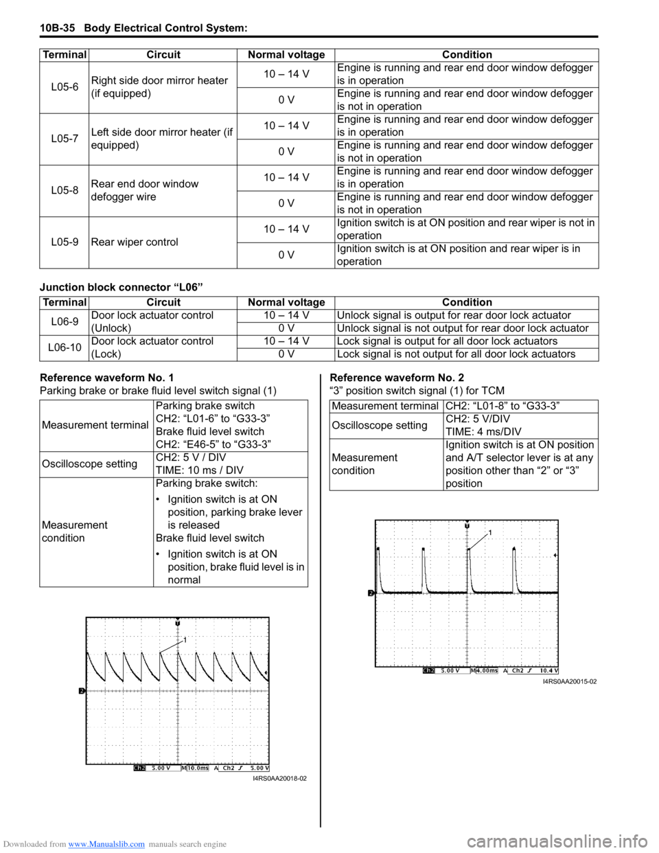
Reference waveform No. 1
Parking brake or brake fluid level switch signal (1)Reference waveform No. 2
“3” position switch signal (1) for TCM
L05-6
Right side door mirror heater
(if equipped) 10 – 14 V
Engine is running and rear end door window defogger
is in operation
0 V Engine is running and rear end door window defogger
is not in operation
L05-7 Left side door mirror heater (if
equipped) 10 – 14 V
Engine is running and rear end door window defogger
is in operation
0 V Engine is running and rear end door window defogger
is not in operation
L05-8 Rear end door window
defogger wire 10 – 14 V
Engine is running and rear end door window defogger
is in operation
0 V Engine is running and rear end door window defogger
is not in operation
L05-9 Rear wiper control 10 – 14 V
Ignition switch is at ON posi
tion and rear wiper is not in
operation
0 V Ignition switch is at ON pos
ition and rear wiper is in
operation
Terminal Circuit Normal voltage Condition
Terminal
CircuitNormal voltage Condition
L06-9 Door lock actuator control
(Unlock) 10 – 14 V Unlock signal is outpu
t for rear door lock actuator
0 V Unlock signal is not output for rear door lock actuator
L06-10 Door lock actuator control
(Lock) 10 – 14 V Lock signal is output for all door lock actuators
0 V Lock signal is not output for all door lock actuators
Measurement terminal Parking brake switch
CH2: “L01-6” to “G33-3”
Brake fluid level switch
CH2: “E46-5” to “G33-3”
Oscilloscope setting CH2: 5 V / DIV
TIME: 10 ms / DIV
Measurement
condition Parking brake switch:
• Ignition switch is at ON
position, parking brake lever
is released
Brake fluid level switch
• Ignition switch is at ON position, brake fluid level is in
normal
I4RS0AA20018-02
Measurement terminal CH2: “L01-8” to “G33-3”
Oscilloscope setting CH2: 5 V/DIV
TIME: 4 ms/DIV
Measurement
condition Ignition switch is at ON position
and A/T selector lever is at any
position other than “2” or “3”
position
I4RS0AA20015-02
Page 1439 of 1496
Downloaded from www.Manualslib.com manuals search engine Body Electrical Control System: 10B-36
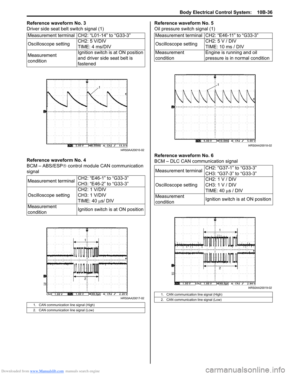
Reference waveform No. 3
Driver side seat belt switch signal (1)
Reference waveform No. 4
BCM – ABS/ESP® control module CAN communication
signal Reference waveform No. 5
Oil pressure switch signal (1)
Reference waveform No. 6
BCM – DLC CAN communication signal
Measurement terminal CH2: “L01-14” to “G33-3”
Oscilloscope setting
CH2: 5 V/DIV
TIME: 4 ms/DIV
Measurement
condition Ignition switch is at ON position
and driver side seat belt is
fastened
Measurement terminal CH2: “E46-1” to “G33-3”
CH3: “E46-2” to “G33-3”
Oscilloscope setting CH2: 1 V/DIV
CH3: 1 V/DIV
TIME: 40
µs/ DIV
Measurement
condition Ignition switch is at ON position
1. CAN communication line signal (High)
2. CAN communication line signal (Low)
I4RS0AA20016-02
I4RS0AA20017-02
Measurement terminal CH2: “E46-11” to “G33-3”
Oscilloscope settingCH2: 5 V / DIV
TIME: 10 ms / DIV
Measurement
condition Engine is running and oil
pressure is in normal condition
Measurement terminal CH2: “G37-1” to “G33-3”
CH3: “G37-3” to “G33-3”
Oscilloscope setting CH2: 1 V / DIV
CH3: 1 V / DIV
TIME: 40
µs / DIV
Measurement
condition Ignition switch is at ON position
1. CAN communication line signal (High)
2. CAN communication line signal (Low)
I4RS0AA20018-02
I4RS0AA20019-02
Page 1440 of 1496
Downloaded from www.Manualslib.com manuals search engine 10B-37 Body Electrical Control System:
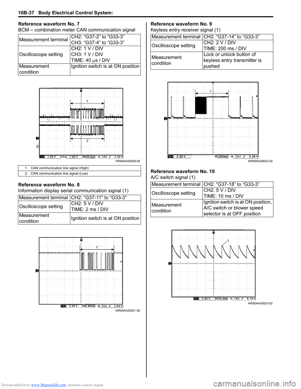
Reference waveform No. 7
BCM – combination meter CAN communication signal
Reference waveform No. 8
Information display serial communication signal (1)Reference waveform No. 9
Keyless entry receiver signal (1)
Reference waveform No. 10
A/C switch signal (1)
Measurement terminal
CH2: “G37-2” to “G33-3”
CH3: “G37-4” to “G33-3”
Oscilloscope setting CH2: 1 V / DIV
CH3: 1 V / DIV
TIME: 40
µs / DIV
Measurement
condition Ignition switch is at ON position
1. CAN communication line signal (High)
2. CAN communication line signal (Low)
Measurement terminal CH2: “G37-11” to “G33-3”
Oscilloscope setting
CH2: 5 V / DIV
TIME: 2 ms / DIV
Measurement
condition Ignition switch is at ON position
I4RS0AA20020-02
I4RS0AA20021-02
Measurement terminal CH2: “G37-14” to “G33-3”
Oscilloscope settingCH2: 2 V / DIV
TIME: 200 ms / DIV
Measurement
condition Lock or unlock button of
keyless entry transmitter is
pushed
Measurement terminal CH2: “G37-18” to “G33-3”
Oscilloscope setting CH2: 5 V / DIV
TIME: 10 ms / DIV
Measurement
condition Ignition switch is at ON position,
A/C switch or blower speed
selector is at OFF position
I4RS0AA20022-02
I4RS0AA20023-02
Page 1441 of 1496
Downloaded from www.Manualslib.com manuals search engine Body Electrical Control System: 10B-38
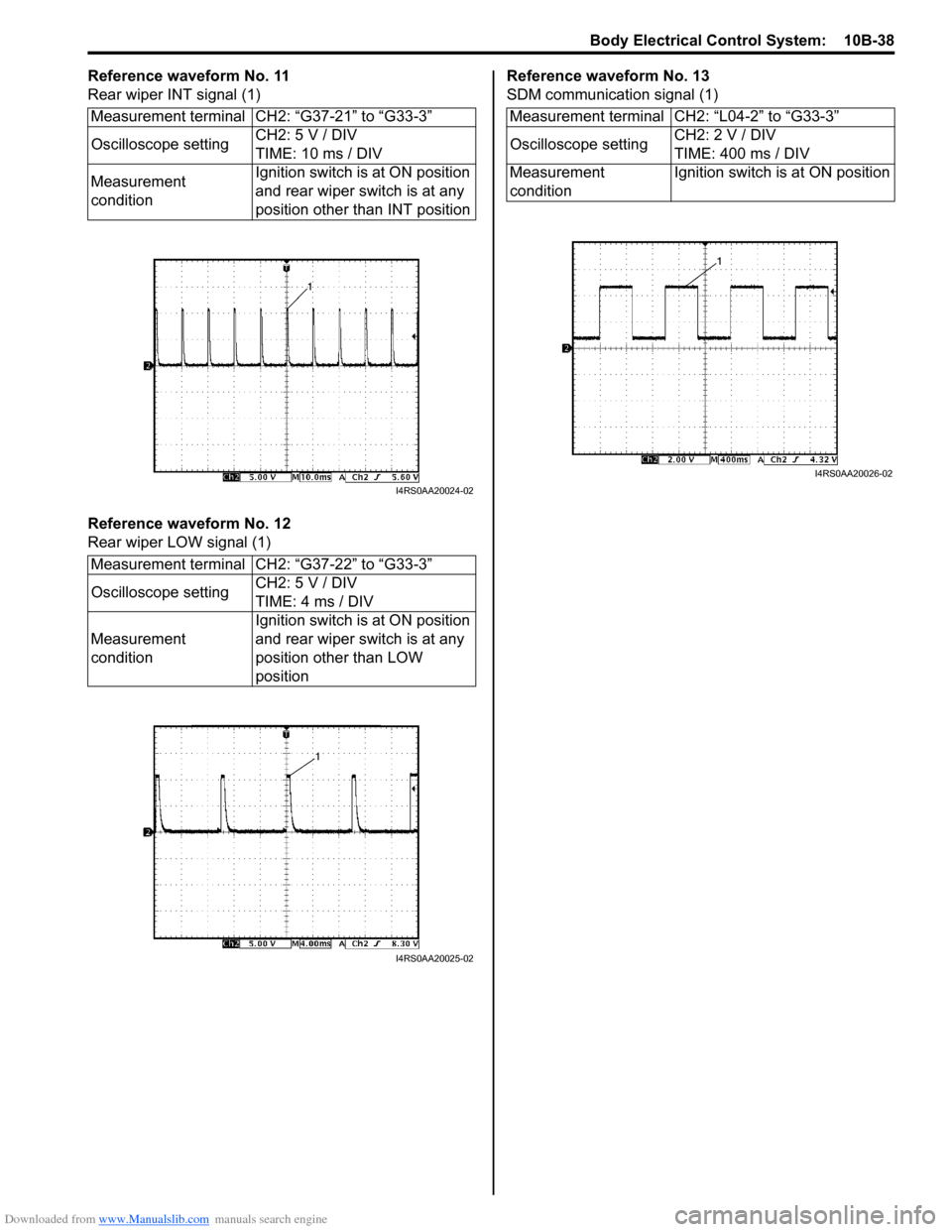
Reference waveform No. 11
Rear wiper INT signal (1)
Reference waveform No. 12
Rear wiper LOW signal (1)Reference waveform No. 13
SDM communication signal (1)
Measurement terminal CH2: “G37-21” to “G33-3”
Oscilloscope setting CH2: 5 V / DIV
TIME: 10 ms / DIV
Measurement
condition Ignition switch is at ON position
and rear wiper switch is at any
position other than INT position
Measurement terminal CH2: “G37-22” to “G33-3”
Oscilloscope setting CH2: 5 V / DIV
TIME: 4 ms / DIV
Measurement
condition Ignition switch is at ON position
and rear wiper switch is at any
position other than LOW
position
I4RS0AA20024-02
I4RS0AA20025-02
Measurement terminal CH2: “L04-2” to “G33-3”
Oscilloscope setting
CH2: 2 V / DIV
TIME: 400 ms / DIV
Measurement
condition Ignition switch is at ON position
I4RS0AA20026-02
Page 1460 of 1496
Downloaded from www.Manualslib.com manuals search engine 10C-17 Immobilizer Control System:
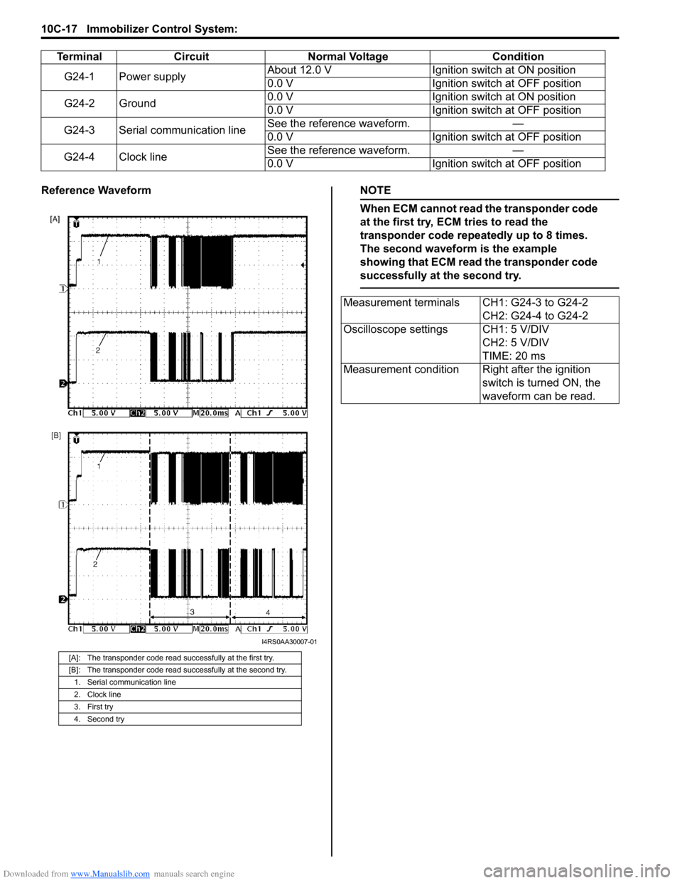
Reference WaveformNOTE
When ECM cannot read the transponder code
at the first try, ECM tries to read the
transponder code repeatedly up to 8 times.
The second waveform is the example
showing that ECM read the transponder code
successfully at the second try.
TerminalCircuit Normal Voltage Condition
G24-1 Power supply About 12.0 V
Ignition switch at ON position
0.0 V Ignition switch at OFF position
G24-2 Ground 0.0 V
Ignition switch at ON position
0.0 V Ignition switch at OFF position
G24-3 Serial communication line See the reference waveform.
—
0.0 V Ignition switch at OFF position
G24-4 Clock line See the reference waveform.
—
0.0 V Ignition switch at OFF position
[A]: The transponder code read successfully at the first try.
[B]: The transponder code read successfully at the second try.
1. Serial communication line
2. Clock line
3. First try
4. Second try
I4RS0AA30007-01
Measurement terminals CH1: G24-3 to G24-2 CH2: G24-4 to G24-2
Oscilloscope settings CH1: 5 V/DIV CH2: 5 V/DIV
TIME: 20 ms
Measurement condition Right after the ignition switch is turned ON, the
waveform can be read.
Page 1478 of 1496
Downloaded from www.Manualslib.com manuals search engine 10E-16 Keyless Start System:
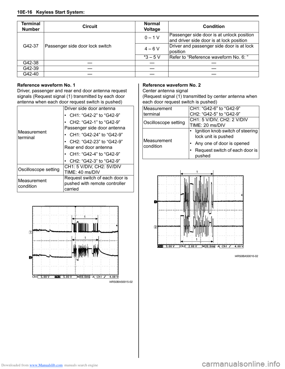
Reference waveform No. 1
Driver, passenger and rear end door antenna request
signals (Request signal (1) transmitted by each door
antenna when each door request switch is pushed)Reference waveform No. 2
Center antenna signal
(Request signal (1) transmitted by center antenna when
each door request switch is pushed)
G42-37 Passenger side door lock switch
0 – 1 V
Passenger side door is at unlock position
and driver side door is at lock position
4 – 6 V Driver and passenger side door is at lock
position
*3 – 5 V Refer to “Reference waveform No. 6: ”
G42-38 — — —
G42-39 — — —
G42-40 — — —
Terminal
Number Circuit Normal
Vo l ta g e Condition
Measurement
terminalDriver side door antenna
• CH1: “G42-2” to “G42-9”
• CH2: “G42-1” to “G42-9”
Passenger side door antenna
• CH1: “G42-24” to “G42-9”
• CH2: “G42-23” to “G42-9”
Rear end door antenna
• CH1: “G42-4” to “G42-9”
• CH2: “G42-3” to “G42-9”
Oscilloscope setting CH1: 5 V/DIV, CH2: 5V/DIV
TIME: 40 ms/DIV
Measurement
condition Request switch of each door is
pushed with remote controller
carried
I4RS0BA50015-02
Measurement
terminal
CH1: “G42-6” to “G42-9”
CH2: “G42-5” to “G42-9”
Oscilloscope setting CH1: 5 V/DIV, CH2: 2 V/DIV
TIME: 20 ms/DIV
Measurement
condition • Ignition knob switch of steering
lock unit is pushed
• Any one of door is opened
• Request switch of each door is pushed
I4RS0BA50016-02
Page 1479 of 1496
Downloaded from www.Manualslib.com manuals search engine Keyless Start System: 10E-17
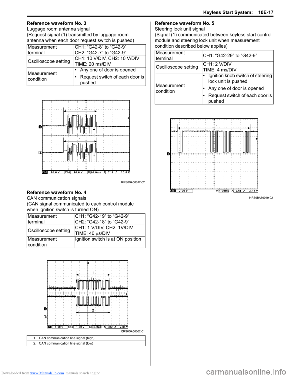
Reference waveform No. 3
Luggage room antenna signal
(Request signal (1) transmitted by luggage room
antenna when each door request switch is pushed)
Reference waveform No. 4
CAN communication signals
(CAN signal communicated to each control module
when ignition switch is turned ON)Reference waveform No. 5
Steering lock unit signal
(Signal (1) communicated between keyless start control
module and steering lock unit when measurement
condition described below applies)
Measurement
terminal CH1: “G42-8” to “G42-9”
CH2: “G42-7” to “G42-9”
Oscilloscope setting CH1: 10 V/DIV, CH2: 10 V/DIV
TIME: 20 ms/DIV
Measurement
condition • Any one of door is opened
• Request switch of each door is
pushed
Measurement
terminal CH1: “G42-19” to “G42-9”
CH2: “G42-18” to “G42-9”
Oscilloscope setting CH1: 1 V/DIV, CH2: 1V/DIV
TIME: 40
µs/DIV
Measurement
condition Ignition switch is at ON position
1. CAN communication line signal (high)
2. CAN communication line signal (low)
I4RS0BA50017-02
I5RS0DA50002-01
Measurement
terminal
CH1: “G42-29” to “G42-9”
Oscilloscope setting CH1: 2 V/DIV
TIME: 4 ms/DIV
Measurement
condition • Ignition knob switch of steering
lock unit is pushed
• Any one of door is opened
• Request switch of each door is pushed
I4RS0BA50019-02