Page 478 of 1496
Downloaded from www.Manualslib.com manuals search engine 3-1 Precautions:
Driveline / Axle
Precautions
Precautions
Precautions for Driveline / AxleS7RS0B3000001
Fastener Caution
Refer to “Fastener Caution in Section 00”.
Page 479 of 1496

Downloaded from www.Manualslib.com manuals search engine Drive Shaft / Axle: 3A-1
Driveline / Axle
Drive Shaft / Axle
General Description
Front Drive Shaft ConstructionS7RS0B3101001
A constant velocity ball joint is used on the wheel side of both right and left side drive shaft assemblies. For A/T
vehicle, a tripod type constant velocity joint is used on the differential side and center shaft side. For M/T vehicle, a
double offset type constant velocity joint (DOJ) is used on the differential side and center shaft side. The drive shaft
can slide through the tripod joint or the double offset joint (DOJ) in the extension/contraction direction.
Component Location
Front Drive Shaft Assembly Components LocationS7RS0B3103001
I6RS0C310002-03
1. To transaxle 8. Ball stud washer : 45 N⋅m (4.5 kgf-m, 32.5 lb-ft)
2. Drive shaft assembly 9. Tie-rod end nut : 60 N⋅m (6.0 kgf-m, 43.5 lb-ft)
3. Tie-rod end 10. Ball stud bolt : 200 N⋅m (20.0 kgf-m, 145.0 lb-ft)
4. Center bearing support 11. Drive shaft nut
: After tightening nut, caulk nut securely. : 85 N
⋅m (8.5 kgf-m, 61.5 lb-ft)
5. Center shaft 12. Wheel nut : Do not reuse.
6. Center bearing support bolts 13. Drive shaft washer
7. Ball stud nut : 55 N⋅m (5.5 kgf-m, 40.0 lb-ft)
Page 480 of 1496
Downloaded from www.Manualslib.com manuals search engine 3A-2 Drive Shaft / Axle:
Diagnostic Information and Procedures
Front Drive Shaft Symptom DiagnosisS7RS0B3104001
ConditionPossible cause Correction / Reference Item
Abnormal noise Worn or breakage of the drive shaft joint Replace.
Worn or breakage of the center bearing Replace.
Page 481 of 1496
Downloaded from www.Manualslib.com manuals search engine Drive Shaft / Axle: 3A-3
Repair Instructions
Front Drive Shaft ComponentsS7RS0B3106001
I6RS0C310003-02
Page 485 of 1496

Downloaded from www.Manualslib.com manuals search engine Drive Shaft / Axle: 3A-7
DOJ
CAUTION!
Disassembly of wheel side joint is not
allowed. If any noise or damage exists in it,
replace it as assembly.
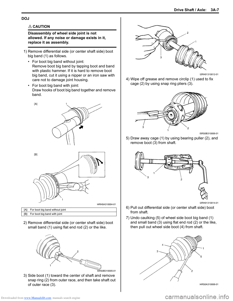
1) Remove differential side (or center shaft side) boot big band (1) as follows.
• For boot big band without joint:Remove boot big band by tapping boot and band
with plastic hammer. If it is hard to remove boot
big band, cut it using a nipper or an iron saw with
care not to damage joint housing.
• For boot big band with joint: Draw hooks of boot big band together and remove
band.
2) Remove differential side (or center shaft side) boot small band (1) using flat end rod (2) or the like.
3) Side boot (1) toward the center of shaft and remove snap ring (2) from outer race, and then take shaft out
of outer race (3). 4) Wipe off grease and remove circlip (1) used to fix
cage (2) by using snap ring pliers (3).
5) Draw away cage (1) by using bearing puller (2), and remove boot (3) from shaft.
6) Pull out differential side (or center shaft side) boot from shaft.
7) Undo caulking (5) of wheel side boot big band (1) and small band (3) using flat end rod (2) or the like,
then pull out wheel side boot (4) from shaft.
[A]: For boot big band without joint
[B]: For boot big band with joint
I4RH0A310004-01
2
1
I5RS0B310005-01
I2RH01310012-01
I5RS0B310006-01
I2RH01310014-01
I4RS0A310006-01
Page 490 of 1496

Downloaded from www.Manualslib.com manuals search engine 3A-12 Drive Shaft / Axle:
10) Set new differential side (or center shaft side) small band and new differential side (or center shaft side)
boot on shaft temporarily.
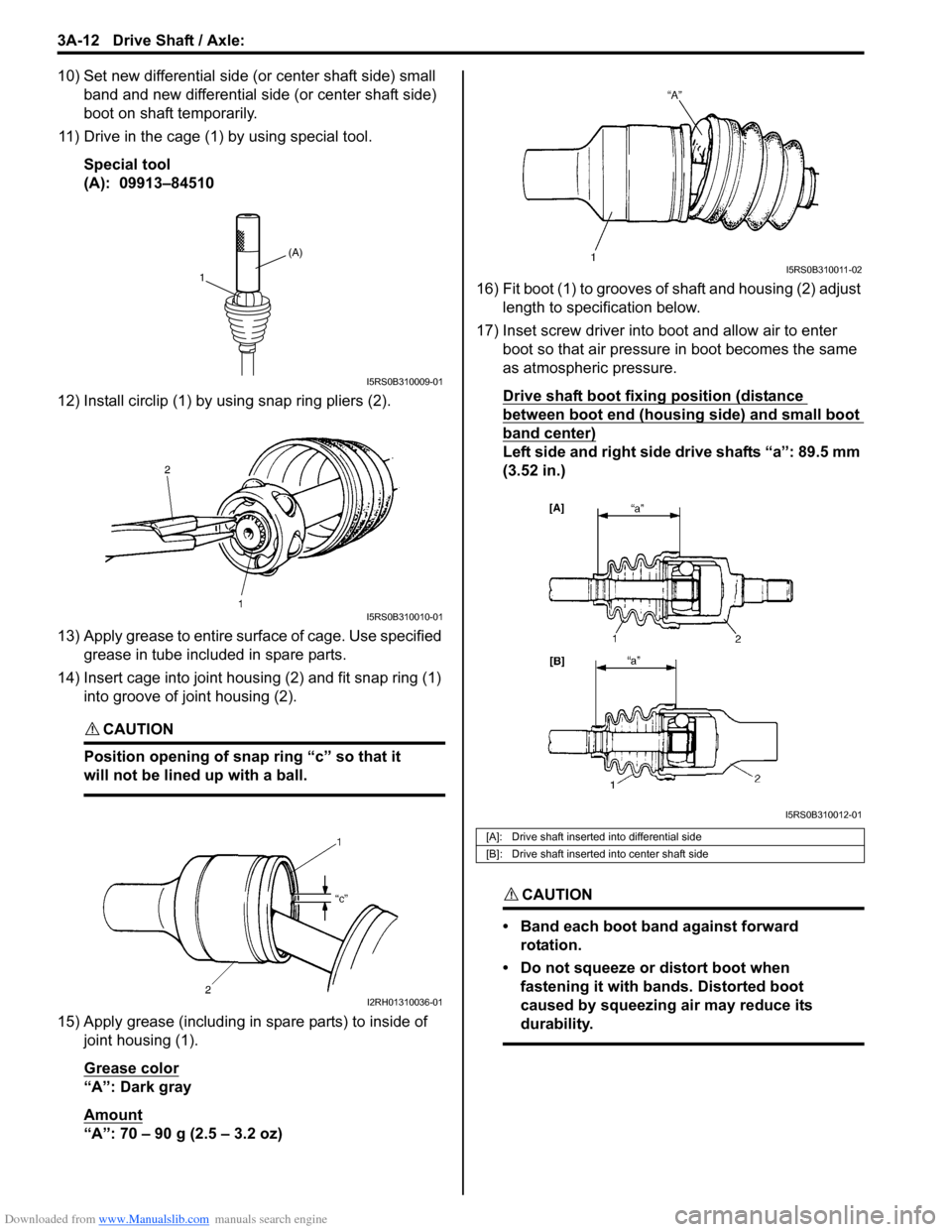
11) Drive in the cage (1) by using special tool.
Special tool
(A): 09913–84510
12) Install circlip (1) by using snap ring pliers (2).
13) Apply grease to entire su rface of cage. Use specified
grease in tube included in spare parts.
14) Insert cage into joint housing (2) and fit snap ring (1) into groove of joint housing (2).
CAUTION!
Position opening of snap ring “c” so that it
will not be lined up with a ball.
15) Apply grease (including in spare parts) to inside of joint housing (1).
Grease color
“A”: Dark gray
Amount
“A”: 70 – 90 g (2.5 – 3.2 oz) 16) Fit boot (1) to grooves of shaft and housing (2) adjust
length to specification below.
17) Inset screw driver into boot and allow air to enter boot so that air pressure in boot becomes the same
as atmospheric pressure.
Drive shaft boot fixing position (distance
between boot end (housing side) and small boot
band center)
Left side and right side drive shafts “a”: 89.5 mm
(3.52 in.)
CAUTION!
• Band each boot band against forward rotation.
• Do not squeeze or distort boot when fastening it with bands. Distorted boot
caused by squeezing air may reduce its
durability.
(A)
1
I5RS0B310009-01
I5RS0B310010-01
I2RH01310036-01
[A]: Drive shaft inserted into differential side
[B]: Drive shaft inserted into center shaft side
I5RS0B310011-02
I5RS0B310012-01
Page 491 of 1496
Downloaded from www.Manualslib.com manuals search engine Drive Shaft / Axle: 3A-13
18) Place differential side boot (or center shaft side) new
big band (3) and new small band (4) onto boot
putting band outer end (1) against forward rotation
(2) as shown in figure.
19) Fasten differential side (or center shaft side) boot band.
• For differential side (or center shaft side) boot big band
Fasten band (1) by drawing hooks (2) with special
tool and engage hooks (3) in slot and window (4).
Special tool
(A): 09943–57021
• For differential side (or center shaft side) boot small band
Fasten band (5) using special tool as shown in
figure.
Distance “a”
: 2.6 ± 1.4 mm (0.102 ± 0.055 in.)
Special tool
(B): 09943–57010
I5JB0A311006-01
(A)
1 4
2 3
(B)
5 “a”
I5RS0B310013-01
Page 492 of 1496

Downloaded from www.Manualslib.com manuals search engine 3A-14 Drive Shaft / Axle:
Center Shaft and Center Bearing Support
Disassembly and Reassembly
S7RS0B3106005
Disassembly1) Remove snap ring and O-ring (M/T model) from center shaft.
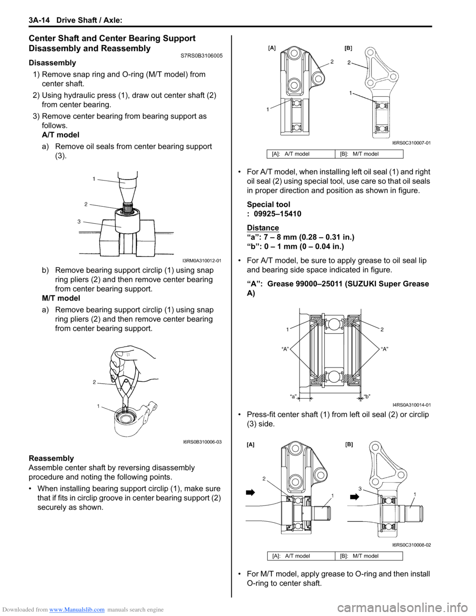
2) Using hydraulic press (1), draw out center shaft (2) from center bearing.
3) Remove center bearing from bearing support as follows.
A/T model
a) Remove oil seals from center bearing support (3).
b) Remove bearing support circlip (1) using snap ring pliers (2) and then remove center bearing
from center bearing support.
M/T model
a) Remove bearing support circlip (1) using snap ring pliers (2) and then remove center bearing
from center bearing support.
Reassembly
Assemble center shaft by reversing disassembly
procedure and noting the following points.
• When installing bearing support circlip (1), make sure
that if fits in circlip groove in center bearing support (2)
securely as shown. • For A/T model, when installing
left oil seal (1) and right
oil seal (2) using special tool, use care so that oil seals
in proper direction and position as shown in figure.
Special tool
: 09925–15410
Distance
“a”: 7 – 8 mm (0.28 – 0.31 in.)
“b”: 0 – 1 mm (0 – 0.04 in.)
• For A/T model, be sure to apply grease to oil seal lip and bearing side space indicated in figure.
“A”: Grease 99000–25011 (SUZUKI Super Grease
A)
• Press-fit center shaft (1) from left oil seal (2) or circlip
(3) side.
• For M/T model, apply grease to O-ring and then install O-ring to center shaft.
I3RM0A310012-01
I6RS0B310006-03
[A]: A/T model [B]: M/T model
[A]: A/T model [B]: M/T model
I6RS0C310007-01
12
“A” “A”
“a” “b”
I4RS0A310014-01
I6RS0C310008-02