2008 SUZUKI SWIFT Power lock
[x] Cancel search: Power lockPage 1407 of 1496
Downloaded from www.Manualslib.com manuals search engine Body Electrical Control System: 10B-4
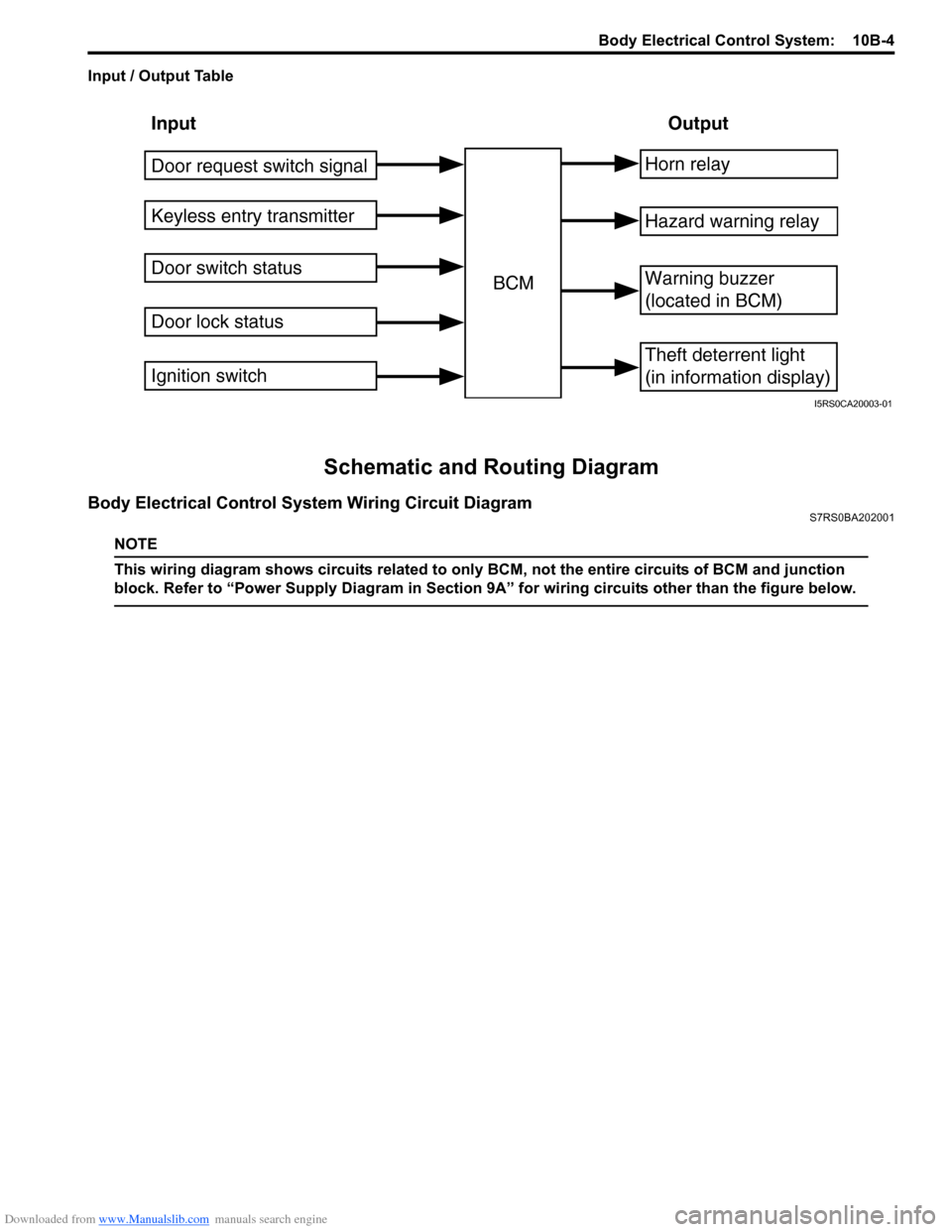
Input / Output Table
Schematic and Routing Diagram
Body Electrical Control System Wiring Circuit DiagramS7RS0BA202001
NOTE
This wiring diagram shows circuits related to only BCM, not the entire circuits of BCM and junction
block. Refer to “Power Supply Diagram in Section 9A” for wiring circuits other than the figure below.
Input Output
Keyless entry transmitter
Door switch status
Door lock status BCMHorn relay
Theft deterrent light
(in information display)
Warning buzzer
(located in BCM)
Hazard warning relay
Door request switch signal
Ignition switch
I5RS0CA20003-01
Page 1412 of 1496
Downloaded from www.Manualslib.com manuals search engine 10B-9 Body Electrical Control System:
Diagnostic Information and Procedures
BCM Self-Diagnosis FunctionS7RS0BA204001
• BCM monitors conditions of the system components and its circuit with ignition switch turned to ON position. When
an abnormality in the system oc curs, the area where that abnormality lies is stored in the memory of EEPROM in
BCM.
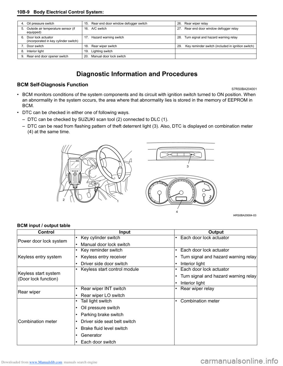
• DTC can be checked in either one of following ways. – DTC can be checked by SUZUKI scan tool (2) connected to DLC (1).
– DTC can be read from flashing pattern of theft deterrent light (3). Also, DTC is displayed on combination meter
(4) at the same time.
BCM input / output table
4. Oil pressure switch 15. Rear end door window defogger switch 26. Rear wiper relay
5. Outside air temperature sensor (if equipped) 16. A/C switch
27. Rear end door window defogger relay
6. Door lock actuator (incorporated in key cylinder switch) 17. Hazard warning switch
28. Turn signal and hazard warning relay
7. Door switch 18. Rear wiper switch 29. Key reminder switch (included in ignition switch)
8. Interior light 19. Lighting switch
9. Rear end door opener switch 20. Manual door lock switch
3
1
2
4I4RS0BA20004-03
Control
Input Output
Power door lock system • Key cylinder switch
• Manual door lock switch • Each door lock actuator
Keyless entry system • Key reminder switch
• Keyless entry receiver
• Driver side door switch • Each door lock actuator
• Turn signal and hazard warning relay
• Interior light
Keyless start system
(Door lock function) • Keyless start control module
• Each door lock actuator
• Turn signal and hazard warning relay
• Interior light
Rear wiper • Rear wiper INT switch
• Rear wiper LO switch • Rear wiper relay
Combination meter • Tail light switch
• Oil pressure switch
• Parking brake switch
• Driver side seat belt switch
• Brake fluid level switch
• Generator
• Each door switch • Combination meter
Page 1414 of 1496
Downloaded from www.Manualslib.com manuals search engine 10B-11 Body Electrical Control System:
Customer Complaint Analysis
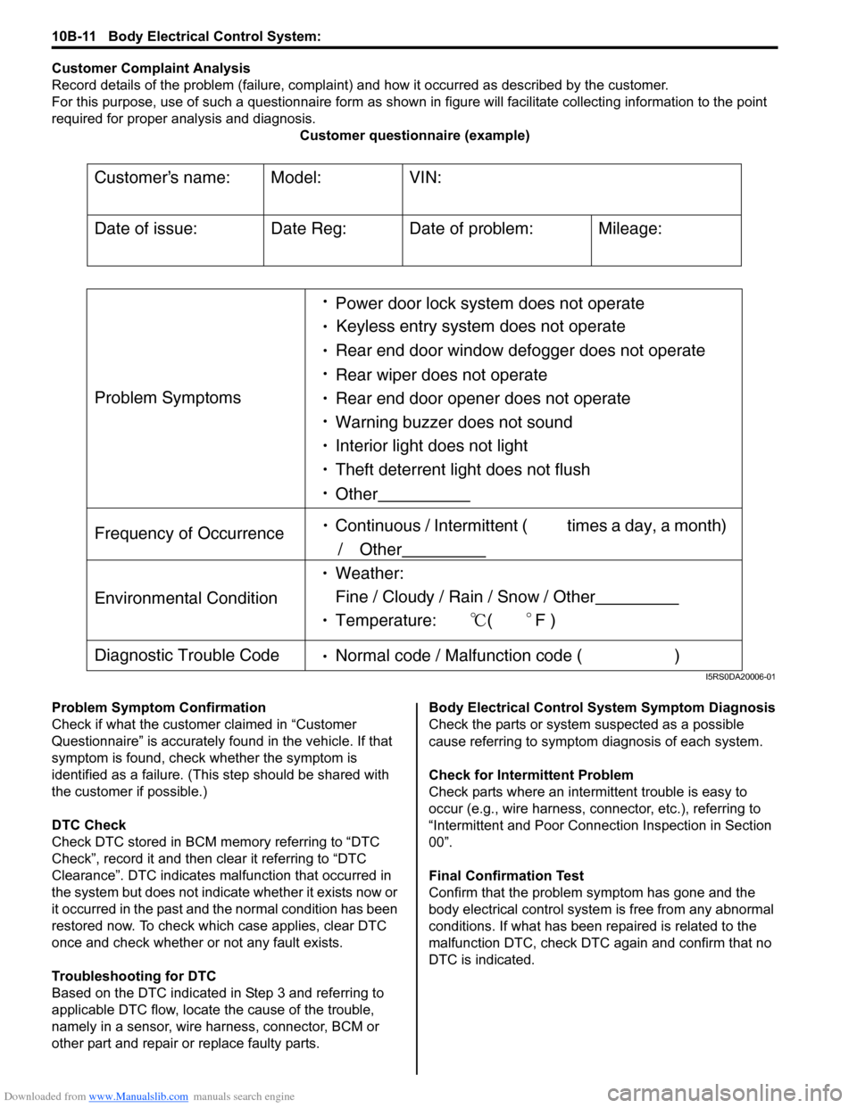
Record details of the problem (failure, complaint) and how it occurred as described by the customer.
For this purpose, use of such a questionnaire form as shown in figure will facilitate collectin g information to the point
required for proper analysis and diagnosis. Customer questionnaire (example)
Problem Symptom Confirmation
Check if what the custom er claimed in “Customer
Questionnaire” is accurately f ound in the vehicle. If that
symptom is found, check whether the symptom is
identified as a failure. (This step should be shared with
the customer if possible.)
DTC Check
Check DTC stored in BCM me mory referring to “DTC
Check”, record it and then clear it referring to “DTC
Clearance”. DTC indicates malfunction that occurred in
the system but does not indicate whether it exists now or
it occurred in the past and the normal condition has been
restored now. To check which case applies, clear DTC
once and check whether or not any fault exists.
Troubleshooting for DTC
Based on the DTC indicated in Step 3 and referring to
applicable DTC flow, locate the cause of the trouble,
namely in a sensor, wire harness, connector, BCM or
other part and repair or replace faulty parts. Body Electrical Control System Symptom Diagnosis
Check the parts or system
suspected as a possible
cause referring to symptom diagnosis of each system.
Check for Intermi ttent Problem
Check parts where an intermit tent trouble is easy to
occur (e.g., wire harness, connector, etc.), referring to
“Intermittent and Poor Connec tion Inspection in Section
00”.
Final Confirmation Test
Confirm that the problem symptom has gone and the
body electrical control system is free from any abnormal
conditions. If what has been repaired is related to the
malfunction DTC, check DTC again and confirm that no
DTC is indicated.
Customers name:
Model:
VIN:
Date of issue:
Date Reg:
Date of problem:
Mileage:
Problem Symptoms
Power door lock system does not operate
Keyless entry system does not operate
Rear end door window defogger does not operate
Rear wiper does not operate
Rear end door opener does not operate
Other
Frequency of Occurrence
Continuous / Intermittent ( times a day, a month)
/ Other
Environmental Condition
Weather:
Fine / Cloudy / Rain / Snow / Other
Temperature: (F )
Diagnostic Trouble Code Normal code / Malfunction code ( )
Warning buzzer does not sound
Interior light does not light
Theft deterrent light does not flush
I5RS0DA20006-01
Page 1419 of 1496
Downloaded from www.Manualslib.com manuals search engine Body Electrical Control System: 10B-16
BCM Power Circuit and Ground Circuit CheckS7RS0BA204007
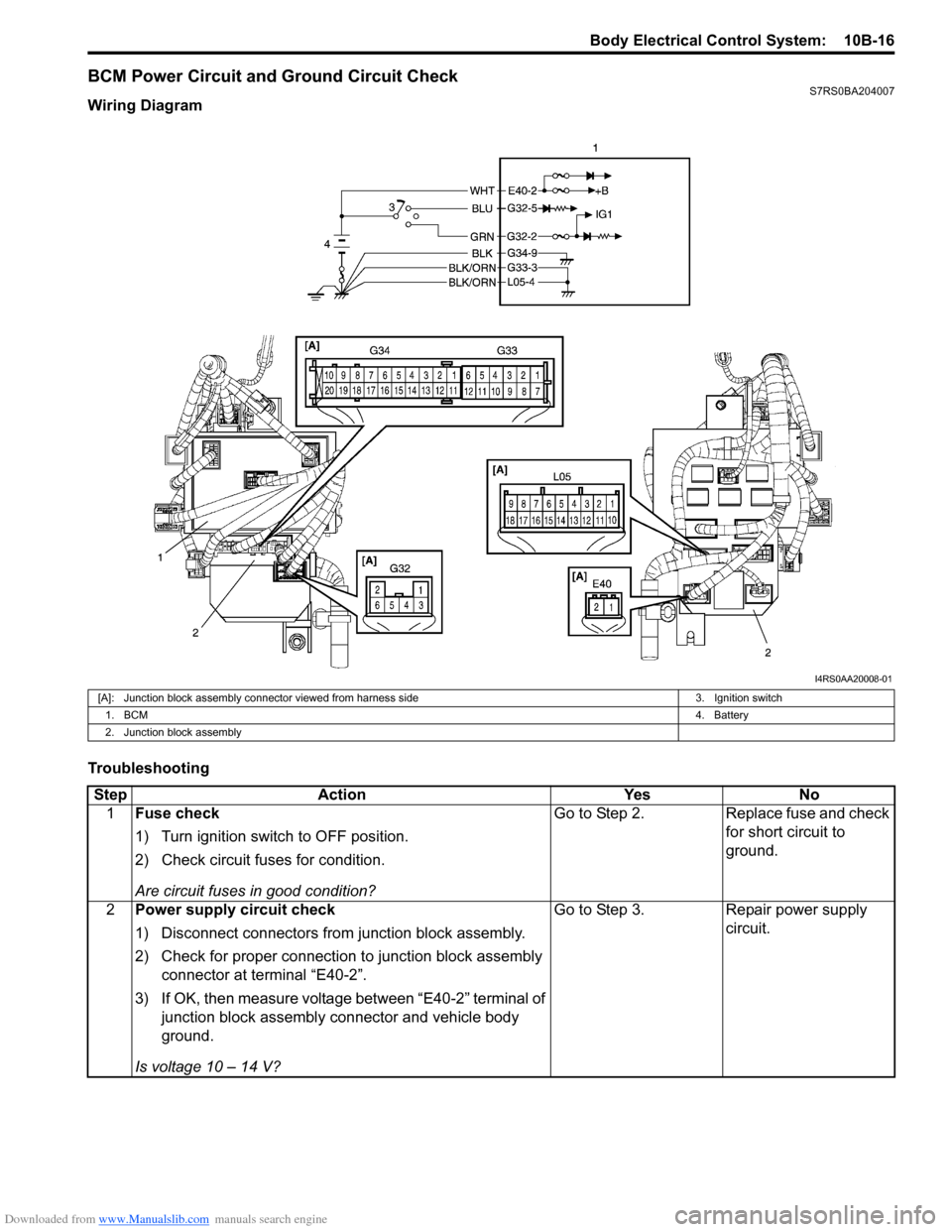
Wiring Diagram
Troubleshooting
I4RS0AA20008-01
[A]: Junction block assembly connector viewed from harness side3. Ignition switch
1. BCM 4. Battery
2. Junction block assembly
Step Action YesNo
1 Fuse check
1) Turn ignition switch to OFF position.
2) Check circuit fuses for condition.
Are circuit fuses in good condition? Go to Step 2.
Replace fuse and check
for short circuit to
ground.
2 Power supply circuit check
1) Disconnect connectors from junction block assembly.
2) Check for proper connection to junction block assembly
connector at terminal “E40-2”.
3) If OK, then measure voltage between “E40-2” terminal of junction block assembly connector and vehicle body
ground.
Is voltage 10 – 14 V? Go to Step 3.
Repair power supply
circuit.
Page 1420 of 1496
Downloaded from www.Manualslib.com manuals search engine 10B-17 Body Electrical Control System:
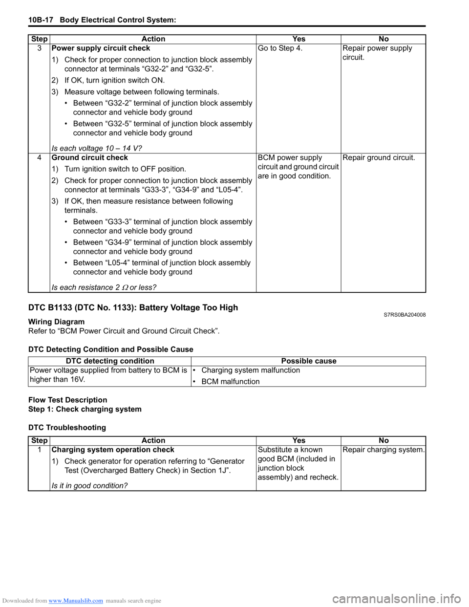
DTC B1133 (DTC No. 1133): Battery Voltage Too HighS7RS0BA204008
Wiring Diagram
Refer to “BCM Power Circuit and Ground Circuit Check”.
DTC Detecting Conditi on and Possible Cause
Flow Test Description
Step 1: Check charging system
DTC Troubleshooting 3
Power supply circuit check
1) Check for proper connection to junction block assembly
connector at terminals “G32-2” and “G32-5”.
2) If OK, turn ignition switch ON.
3) Measure voltage between following terminals. • Between “G32-2” terminal of junction block assembly connector and vehicle body ground
• Between “G32-5” terminal of junction block assembly connector and vehicle body ground
Is each voltage 10 – 14 V? Go to Step 4. Repair power supply
circuit.
4 Ground circuit check
1) Turn ignition switch to OFF position.
2) Check for proper connection to junction block assembly
connector at terminals “G33-3”, “G34-9” and “L05-4”.
3) If OK, then measure resistance between following terminals.
• Between “G33-3” terminal of junction block assembly connector and vehicle body ground
• Between “G34-9” terminal of junction block assembly connector and vehicle body ground
• Between “L05-4” terminal of junction block assembly connector and vehicle body ground
Is each resistance 2
Ω or less? BCM power supply
circuit and ground circuit
are in good condition.
Repair ground circuit.
Step Action Yes No
DTC detecting condition
Possible cause
Power voltage supplied from battery to BCM is
higher than 16V. • Charging system malfunction
• BCM malfunction
Step
Action YesNo
1 Charging system operation check
1) Check generator for operation referring to “Generator
Test (Overcharged Battery Check) in Section 1J”.
Is it in good condition? Substitute a known
good BCM (included in
junction block
assembly) and recheck.
Repair charging system.
Page 1423 of 1496
Downloaded from www.Manualslib.com manuals search engine Body Electrical Control System: 10B-20
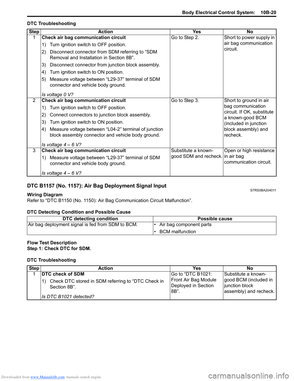
DTC Troubleshooting
DTC B1157 (No. 1157): Air Bag Deployment Signal InputS7RS0BA204011
Wiring Diagram
Refer to “DTC B1150 (No. 1150): Air Bag Communication Circuit Malfunction”.
DTC Detecting Conditi on and Possible Cause
Flow Test Description
Step 1: Check DTC for SDM.
DTC Troubleshooting Step Action Yes No
1 Check air bag communication circuit
1) Turn ignition switch to OFF position.
2) Disconnect connector from SDM referring to “SDM
Removal and Installation in Section 8B”.
3) Disconnect connector from junction block assembly.
4) Turn ignition switch to ON position.
5) Measure voltage between “L29-37” terminal of SDM connector and vehicle body ground.
Is voltage 0 V? Go to Step 2. Short to power supply in
air bag communication
circuit.
2 Check air bag communication circuit
1) Turn ignition switch to OFF position.
2) Connect connectors to junction block assembly.
3) Turn ignition switch to ON position.
4) Measure voltage between “L04-2” terminal of junction
block assembly connector and vehicle body ground.
Is voltage 4 – 6 V? Go to Step 3.
Short to ground in air
bag communication
circuit. If OK, substitute
a known-good BCM
(included in junction
block assembly) and
recheck.
3 Check air bag communication circuit
1) Measure voltage between “L29-37” terminal of SDM
connector and vehicle body ground.
Is voltage 4 – 6 V? Substitute a known-
good SDM and recheck.
Open or high resistance
in air bag
communication circuit.
DTC detecting condition
Possible cause
Air bag deployment signal is fed from SDM to BCM. • Air bag component parts
• BCM malfunction
StepAction YesNo
1 DTC check of SDM
1) Check DTC stored in SDM re ferring to “DTC Check in
Section 8B”.
Is DTC B1021 detected? Go to “DTC B1021:
Front Air Bag Module
Deployed in Section
8B”.
Substitute a known-
good BCM (included in
junction block
assembly) and recheck.
Page 1428 of 1496
Downloaded from www.Manualslib.com manuals search engine 10B-25 Body Electrical Control System:
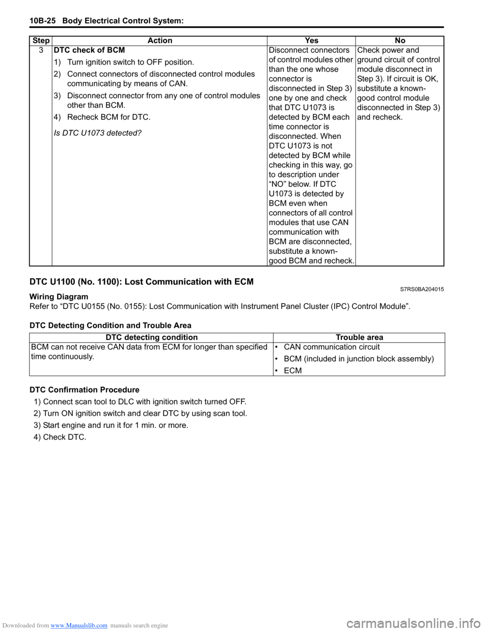
DTC U1100 (No. 1100): Lost Communication with ECMS7RS0BA204015
Wiring Diagram
Refer to “DTC U0155 (No. 0155): Lost Communication with Instrument Panel Cluster (IPC) Control Module”.
DTC Detecting Condition and Trouble Area
DTC Confirmation Procedure 1) Connect scan tool to DLC with ignition switch turned OFF.
2) Turn ON ignition switch and clear DTC by using scan tool.
3) Start engine and run it for 1 min. or more.
4) Check DTC. 3
DTC check of BCM
1) Turn ignition switch to OFF position.
2) Connect connectors of disconnected control modules
communicating by means of CAN.
3) Disconnect connector from any one of control modules other than BCM.
4) Recheck BCM for DTC.
Is DTC U1073 detected? Disconnect connectors
of control modules other
than the one whose
connector is
disconnected in Step 3)
one by one and check
that DTC U1073 is
detected by BCM each
time connector is
disconnected. When
DTC U1073 is not
detected by BCM while
checking in this way, go
to description under
“NO” below. If DTC
U1073 is detected by
BCM even when
connectors of all control
modules that use CAN
communication with
BCM are disconnected,
substitute a known-
good BCM and recheck.Check power and
ground circuit of control
module disconnect in
Step 3). If circuit is OK,
substitute a known-
good control module
disconnected in Step 3)
and recheck.
Step Action Yes No
DTC detecting condition
Trouble area
BCM can not receive CAN data from ECM for longer than specified
time continuously. • CAN communication circuit
• BCM (included in junction block assembly)
•ECM
Page 1430 of 1496
Downloaded from www.Manualslib.com manuals search engine 10B-27 Body Electrical Control System:
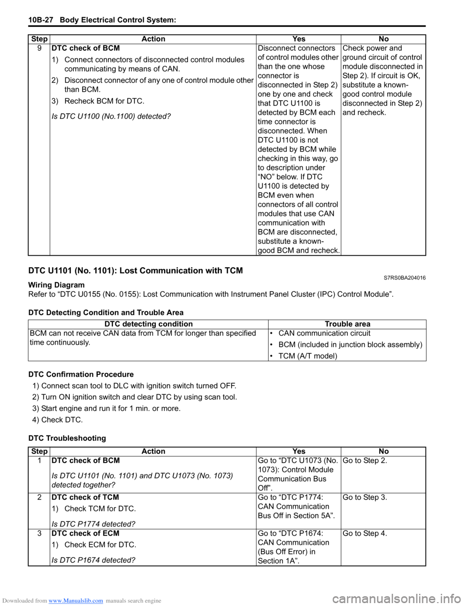
DTC U1101 (No. 1101): Lost Communication with TCMS7RS0BA204016
Wiring Diagram
Refer to “DTC U0155 (No. 0155): Lost Communication with Instrument Panel Cluster (IPC) Control Module”.
DTC Detecting Condition and Trouble Area
DTC Confirmation Procedure 1) Connect scan tool to DLC with ignition switch turned OFF.
2) Turn ON ignition switch and clear DTC by using scan tool.
3) Start engine and run it for 1 min. or more.
4) Check DTC.
DTC Troubleshooting 9
DTC check of BCM
1) Connect connectors of disconnected control modules
communicating by means of CAN.
2) Disconnect connector of any one of control module other than BCM.
3) Recheck BCM for DTC.
Is DTC U1100 (No.1100) detected? Disconnect connectors
of control modules other
than the one whose
connector is
disconnected in Step 2)
one by one and check
that DTC U1100 is
detected by BCM each
time connector is
disconnected. When
DTC U1100 is not
detected by BCM while
checking in this way, go
to description under
“NO” below. If DTC
U1100 is detected by
BCM even when
connectors of all control
modules that use CAN
communication with
BCM are disconnected,
substitute a known-
good BCM and recheck.Check power and
ground circuit of control
module disconnected in
Step 2). If circuit is OK,
substitute a known-
good control module
disconnected in Step 2)
and recheck.
Step Action Yes No
DTC detecting condition
Trouble area
BCM can not receive CAN data from TCM for longer than specified
time continuously. • CAN communication circuit
• BCM (included in junction block assembly)
• TCM (A/T model)
Step
Action YesNo
1 DTC check of BCM
Is DTC U1101 (No. 1101) and DTC U1073 (No. 1073)
detected together? Go to “DTC U1073 (No.
1073): Control Module
Communication Bus
Off”.Go to Step 2.
2 DTC check of TCM
1) Check TCM for DTC.
Is DTC P1774 detected? Go to “DTC P1774:
CAN Communication
Bus Off in Section 5A”.
Go to Step 3.
3 DTC check of ECM
1) Check ECM for DTC.
Is DTC P1674 detected? Go to “DTC P1674:
CAN Communication
(Bus Off Error) in
Section 1A”.Go to Step 4.