2008 SUZUKI SWIFT Electrical wiring
[x] Cancel search: Electrical wiringPage 4 of 1496

Downloaded from www.Manualslib.com manuals search engine 00
0
1
2
3
4
5
6
7
8
9
10
11
Vo l u m e 1
Precautions............................................................... 00-iPrecautions ............................................................ 00-1
General Information ................ ................................... 0-i
General Information ............................................... 0A-1
Maintenance and Lubricatio n ................................. 0B-1
Engine ......................................................................... 1-i Precautions .............................................................. 1-1
Engine General Information and Diagnosis ........... 1A-1
Aux. Emission Control Devices .............................. 1B-1
Engine Electrical Devices....................................... 1C-1
Engine Mechanical ................................................. 1D-1
Engine Lubrication System .................................... 1E-1
Engine Cooling System .......................................... 1F-1
Fuel System ...........................................................1G-1
Ignition System....................................................... 1H-1
Starting System ....................................................... 1I-1
Charging System.....................................................1J-1
Exhaust System ..................................................... 1K-1
Suspension ................................................................. 2-i Precautions .............................................................. 2-1
Suspension General Diagnosis .............................. 2A-1
Front Suspension ................................................... 2B-1
Rear Suspension................ .................................... 2C-1
Wheels and Tires ................................................... 2D-1
Driveline / Axle ........................................................... 3-i Precautions .............................................................. 3-1
Drive Shaft / Axle ................................................... 3A-1
Brakes ......................................................................... 4-i Precautions .............................................................. 4-1
Brake Control System and Diagnosis .................... 4A-1
Front Brakes........................................................... 4B-1
Rear Brakes ........................................................... 4C-1
Parking Brake......................................................... 4D-1
ABS ........................................................................ 4E-1
Electronic Stability Program ................................... 4F-1
Vo l u m e 2
Precautions ............................................................... 00-iPrecautions ............................................................ 00-1
Transmission / Transaxle .... ...................................... 5-i
Precautions .............................................................. 5-1
Automatic Transmission/Transaxle ........................ 5A-1
Manual Transmission/Transaxle ............................ 5B-1
Clutch .....................................................................5C-1
Steering ....................................................................... 6-i Precautions .............................................................. 6-1
Steering General Diagnosis ................................... 6A-1
Steering Wheel and Column .................................. 6B-1
Power Assisted Steering System ...........................6C-1
HVAC ........................................................................... 7-i Precautions .............................................................. 7-1
Heater and Ventilation............................................ 7A-1
Air Conditioning System ......................................... 7B-1
Restraint ...................................................................... 8-i Precautions .............................................................. 8-1
Seat Belts ............................................................... 8A-1
Air Bag System ...................................................... 8B-1
Body, Cab and Accessories .... .................................. 9-i
Precautions .............................................................. 9-1
Wiring Systems ...................................................... 9A-1
Lighting Systems .................................................... 9B-1
Instrumentation / Driver Info. / Horn .......................9C-1
Wipers / Washers ...................................................9D-1
Glass / Windows / Mirrors ...................................... 9E-1
Security and Locks ................................................. 9F-1
Seats ..................................................................... 9G-1
Interior Trim ............................................................9H-1
Hood / Fenders / Doors .......................................... 9J-1
Body Structure ....................................................... 9K-1
Paint / Coatings ...................................................... 9L-1
Exterior Trim .......................................................... 9M-1
Control Systems ....................................................... 10-i Precautions ............................................................ 10-1
Body Electrical Control Sy stem ............................ 10B-1
Immobilizer Control System .................................10C-1
Keyless Start System ........................................... 10E-1
TABLE OF CONTENTS
Page 13 of 1496

Downloaded from www.Manualslib.com manuals search engine Precautions: 00-8
Precautions for Electrical Circuit ServiceS7RS0B0000008
• When replacing a fuse, make sure to use a fuse of the specified capacity. Use of a fuse with a larger capacity
will cause a damage to the electrical parts and a fire.
• When disconnecting and connecting coupler, make sure to turn ignition switch OFF, or electronic parts
may get damaged.
• When disconnecting connectors, never pull the wiring harness. Unlock the connecto r lock first and then pull
them apart by holding connectors themselves. • When connecting connectors, also hold connectors
and put them together until th ey lock securely (a click
is heard).
• When installing the wiring harness, fix it with clamps so that no slack is left.
• When installing vehicle parts, be careful so that the wiring harness is not interfered with or caught by any
other part.
• To avoid damage to the harnes s, protect its part which
may contact against a part forming a sharp angle by
winding tape or the like around it.
I2RH01010038-01
I2RH01010039-01
I2RH01010040-01
I2RH01010041-01
I2RH01010042-01
I2RH01010043-01
I2RH01010044-01
Page 18 of 1496

Downloaded from www.Manualslib.com manuals search engine 00-13 Precautions:
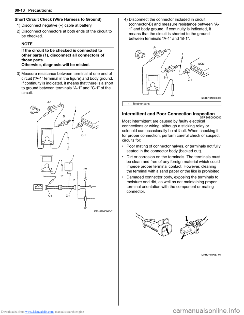
Short Circuit Check (Wire Harness to Ground)1) Disconnect negative (–) cable at battery.
2) Disconnect connectors at bot h ends of the circuit to
be checked.
NOTE
If the circuit to be checked is connected to
other parts (1), disconnect all connectors of
those parts.
Otherwise, diagnosis will be misled.
3) Measure resistance between terminal at one end of circuit (“A-1” terminal in the figure) and body ground.
If continuity is indicated, it means that there is a short
to ground between terminals “A-1” and “C-1” of the
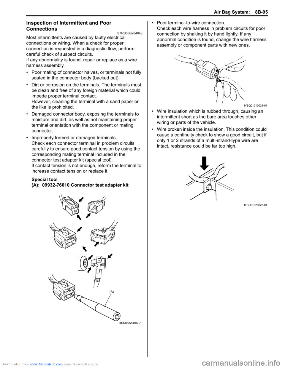
circuit. 4) Disconnect the connector included in circuit
(connector-B) and measure resistance between “A-
1” and body ground. If continuity is indicated, it
means that the circuit is shorted to the ground
between terminals “A-1” and “B-1”.
Intermittent and Poor Connection InspectionS7RS0B0006002
Most intermittent are caused by faulty electrical
connections or wiring, although a sticking relay or
solenoid can occasionally be at fault. When checking it
for proper connection, perfor m careful check of suspect
circuits for:
• Poor mating of connector halves, or terminals not fully seated in the connector body (backed out).
• Dirt or corrosion on the terminals. The terminals must be clean and free of any foreign material which could
impede proper terminal contact. However, cleaning
the terminal with a sand paper or the like is prohibited.
• Damaged connector body, exposing the terminals to moisture and dirt, as well as not maintaining proper
terminal orientation with the component or mating
connector.
I5RH01000006-01
1. To other parts
I2RH01010056-01
I2RH01010057-01
Page 414 of 1496

Downloaded from www.Manualslib.com manuals search engine 1J-4 Charging System:
Diagnostic Information and Procedures
Battery InspectionS7RS0B1A04001
Common Causes of Failure
A battery is not designed to last indefinitely; however, with proper care, it will provide many years of service. If the
battery performs satisfactorily during te st but fails to operate properly for no apparent reason, the following are some
factors that may point to the cause of trouble:
• Accessories left on overnight or for an extended period without the generator operating.
• Slow average driving speeds for short periods.
• Electrical load exceeding generator output partic ularly with addition of aftermarket equipment.
• Defects in charging system such as high resistance, s lipping drive belt, loose generator output terminal, faulty
generator or voltage regulator, Refer to “Generator Symptom Diagnosis”.
• Battery abuse, including failure to keep battery cable terminals clean and tight or loose battery hold down.
• Mechanical problems in electrical sys tem such as shorted or pinched wires.
Visual Inspection
Check for obvious damage, such as cracked or broken case or cover, that could permit loss of electrolyte. If obvious
damage is noted, replace battery. Determine cause of damage and correct as needed.
Generator Symptom DiagnosisS7RS0B1A04002
CAUTION!
• Do not mistake polarities of “IG” terminal and “L” terminal.
• Do not create short circuit between “IG” and “L” terminals. Always connect these terminals through a lamp.
• Do not connect any load between “L” and “E” terminals.
• When connecting charger or booster battery to vehicle battery, refer to “Jump Starting in Case of Emergency”.
Trouble in charging system will show up as one or more of the following conditions:
1) Faulty indicator lamp operation.
2) An undercharged battery as evidenced by slow cranking or indicator dark.
3) An overcharged battery as evidenced by ex cessive spewing of electrolyte from vents.
Condition Possible cause Correction / Reference Item
Noisy generator Loose drive belt Adjust or replace drive belt.
Loose drive belt pulley Tighten by specified torque.
Loose mounting bolts Tighten by specified torque.
Worn or dirty bearings Replace.
Defective diode or stator Replace.
Charge light does not
light with ignition ON and
engine off Fuse blown
Replace fuse and check for shorted circuit.
Indicator lamp (LED) faulty Replace combination meter.
Wiring connection loose Tighten loose connection.
IC regulator or field coil faulty Replace.
Poor contact between brush and slip
ring Repair or replace.
Charge light does not go
out with engine running
(battery requires frequent
recharging) Drive belt loose or worn
Adjust or replace drive belt.
IC regulator or generator faulty Replace.
Wiring faulty Repair wiring.
Page 1133 of 1496

Downloaded from www.Manualslib.com manuals search engine Air Bag System: 8B-95
Inspection of Intermittent and Poor
Connections
S7RS0B8204048
Most intermittents are caused by faulty electrical
connections or wiring. When a check for proper
connection is requested in a diagnostic flow, perform
careful check of suspect circuits.
If any abnormality is found, repair or replace as a wire
harness assembly.
• Poor mating of connector halves, or terminals not fully seated in the connector body (backed out).
• Dirt or corrosion on the terminals. The terminals must be clean and free of any foreign material which could
impede proper terminal contact.
However, cleaning the terminal with a sand paper or
the like is prohibited.
• Damaged connector body, exposing the terminals to moisture and dirt, as well as not maintaining proper
terminal orientation with the component or mating
connector.
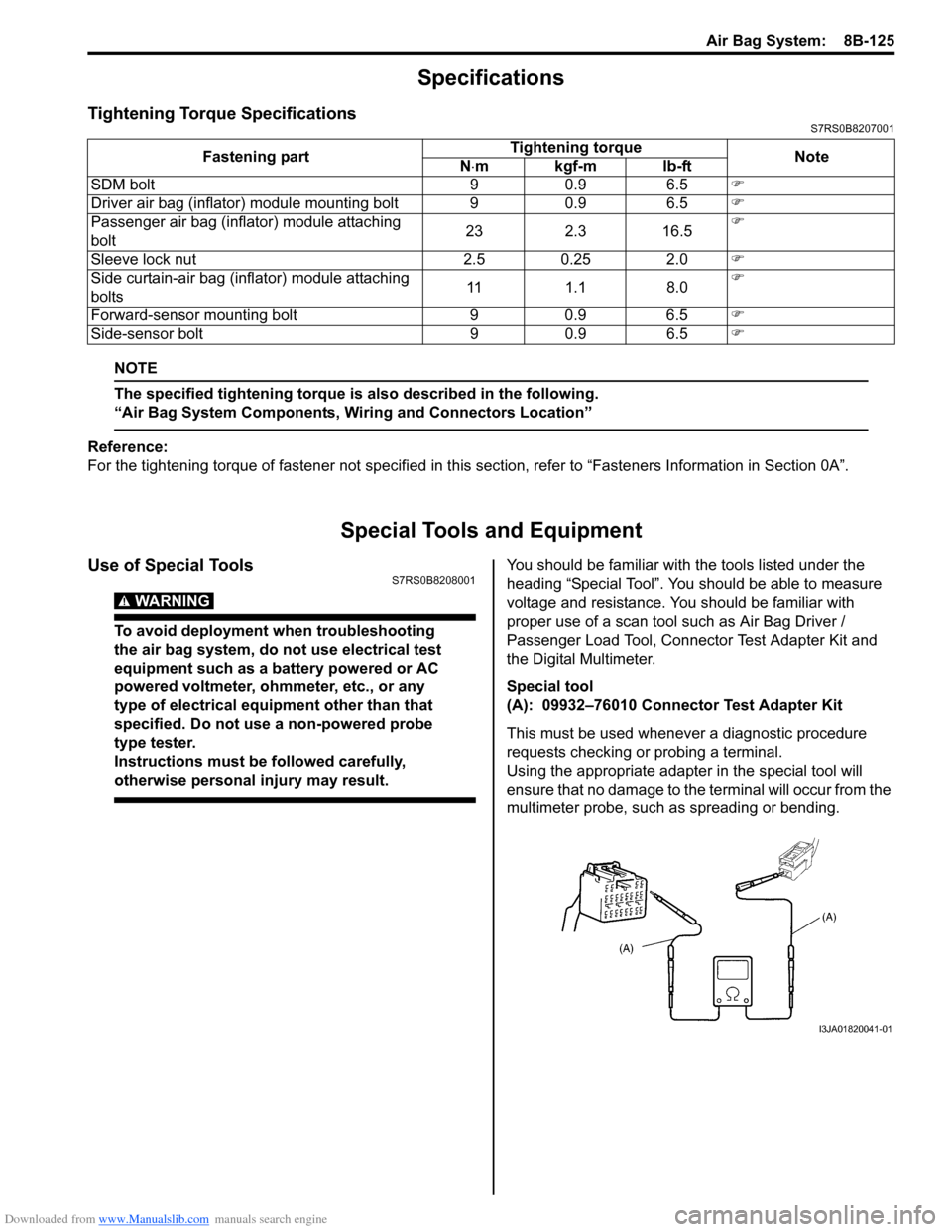
• Improperly formed or damaged terminals. Check each connector terminal in problem circuits
carefully to ensure good contact tension by using the
corresponding mating terminal included in the
connector test adapter kit (special tool).
If contact tension is not e nough, reform the terminal to
increase contact tension or replace it.
Special tool
(A): 09932-76010 Connector test adapter kit • Poor terminal-to-wire connection.
Check each wire harness in problem circuits for poor
connection by shaking it by hand lightly. If any
abnormal condition is found, change the wire harness
assembly or component parts with new ones.
• Wire insulation which is rubbed through, causing an intermittent short as the bare area touches other
wiring or parts of the vehicle.
• Wire broken inside the insulation. This condition could cause a continuity check to show a good circuit, but if
only 1 or 2 strands of a multi-strand-type wire are
intact, resistance could be far too high.
(A)
I4RS0A820045-01
IYSQ01010028-01
IYSQ01820025-01
Page 1163 of 1496

Downloaded from www.Manualslib.com manuals search engine Air Bag System: 8B-125
Specifications
Tightening Torque SpecificationsS7RS0B8207001
NOTE
The specified tightening torque is also described in the following.
“Air Bag System Components, Wiring and Connectors Location”
Reference:
For the tightening torque of fastener not specified in this section, refer to “Fasteners Information in Section 0A”.
Special Tools and Equipment
Use of Special ToolsS7RS0B8208001
WARNING!
To avoid deployment when troubleshooting
the air bag system, do not use electrical test
equipment such as a battery powered or AC
powered voltmeter, ohmmeter, etc., or any
type of electrical equipment other than that
specified. Do not use a non-powered probe
type tester.
Instructions must be followed carefully,
otherwise personal injury may result.
You should be familiar with the tools listed under the
heading “Special Tool”. You should be able to measure
voltage and resistance. You should be familiar with
proper use of a scan tool such as Air Bag Driver /
Passenger Load Tool, Connector Test Adapter Kit and
the Digital Multimeter.
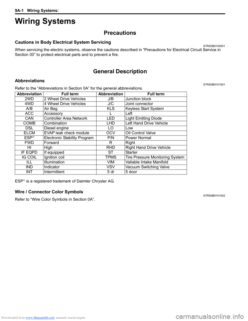
Special tool
(A): 09932–76010 Connector Test Adapter Kit
This must be used whenever a diagnostic procedure
requests checking or probing a terminal.
Using the appropriate adapter in the special tool will
ensure that no damage to the terminal will occur from the
multimeter probe, such as spreading or bending.
Fastening part
Tightening torque
Note
N ⋅mkgf-mlb-ft
SDM bolt 9 0.9 6.5 �)
Driver air bag (inflator) module mounting bolt 9 0.9 6.5 �)
Passenger air bag (inflator) module attaching
bolt 23 2.3 16.5�)
Sleeve lock nut 2.5 0.25 2.0 �)
Side curtain-air bag (inflator) module attaching
bolts 11 1.1 8.0�)
Forward-sensor mounting bolt 9 0.9 6.5 �)
Side-sensor bolt 9 0.9 6.5 �)
I3JA01820041-01
Page 1167 of 1496

Downloaded from www.Manualslib.com manuals search engine Table of Contents 9- i
9
Section 9
CONTENTS
Body, Cab and Accessories
Precautions ................................................. 9-1
Precautions............................................................. 9-1
Precautions on Body, Cab and Accessories ......... 9-1
Precautions for Body Service ................................ 9-1
Fastener Caution for Body Service ....................... 9-1
Wiring Systems............... ......................... 9A-1
Precautions........................................................... 9A-1
Cautions in Body Electrical System Servicing..... 9A-1
General Description ............................................. 9A-1 Abbreviations ...................................................... 9A-1
Wire / Connector Color Sy mbols ......................... 9A-1
Symbols and Marks ............................................ 9A-2
How to Read Connector Layout Diagram ........... 9A-4
How to Read Connector Codes and Terminal Nos.................................................................... 9A-5
How to Read Ground Point ................................. 9A-7
How to Read Power Supply Diagram.................. 9A-8
How to Read System Circuit Diagram................. 9A-8
Connector Layout Diagram . .............................. 9A-10
Connector Layout Diagram ............................... 9A-10
Engine Compartment .......... .............................. 9A-10
Instrument Panel ............................................... 9A-16
Door, Roof......................................................... 9A-20
Floor .................................................................. 9A-23
Rear .................................................................. 9A-29
Ground Point ...................................................... 9A-30 Ground (earth) Point ......................................... 9A-30
Power Supply Diagram ........ .............................. 9A-31
Power Supply Diagram ....... .............................. 9A-31
Fuses and the Protected Parts ......................... 9A-33
Fuses in Main Fuse Box (RHD) ........................ 9A-33
Fuses in Main Fuse Box (LHD) ......................... 9A-33
Individual Circuit Fuse Box No. 1 ...................... 9A-34
Individual Circuit Fuse Box No. 2 (In J/B) ......... 9A-35
Junction Block (J/B) Connector / Fuse Layout .. 9A-37
Junction Block Inner Circuit (Overview) ............ 9A-38
Junction Block Inner Circuit (Detail) .................. 9A-40
System Circuit Diagram... .................................. 9A-45
System Circuit Diagram .. .................................. 9A-45
A-1 Cranking System Circ uit Diagram .............. 9A-46
A-2 Charging System Circu it Diagram .............. 9A-47
A-3 Ignition System Circu it Diagram ................. 9A-48
A-4 Cooling System Circuit Diagram................. 9A-49 A-5 Engine and A/C Control System Circuit
Diagram........................................................... 9A-50
A-6 A/T Control System Circuit Diagram........... 9A-55
A-7 Immobilizer System Circuit Diagram .......... 9A-57
A-8 Body Control System Circuit Diagram ........ 9A-58
B-1 Windshield Wiper and Washer Circuit Diagram........................................................... 9A-62
B-2 Rear Wiper and Washer Circuit Diagram ... 9A-63
B-3 Rear Defogger Circuit Diagram .................. 9A-64
B-4 Power Window Circuit Diagram .................. 9A-65
B-5 Power Door Lock Circu it Diagram .............. 9A-67
B-6 Power Mirror Circuit Diagram ..................... 9A-69
B-7 Horn Circuit Diagram .................................. 9A-70
B-8 Seat Heater Circuit Diagram....................... 9A-71
B-9 Keyless Start System Circuit Diagram........ 9A-72
C-1 Combination Mete r Circuit Diagram
(Meter)............................................................. 9A-73
C-2 Combination Mete r Circuit Diagram
(Indicator) ........................................................ 9A-74
C-3 Combination Mete r Circuit Diagram
(Warning Light)................................................ 9A-75
D-1 Headlight System Circuit Diagram ............. 9A-77
D-2 Position, Tail and Licence Plate Light System Circuit Diagram .................................. 9A-79
D-3 Front Fog Light System Circuit Diagram .... 9A-80
D-4 Illumination Light System Circuit Diagram .. 9A-81
D-5 Interior Light System Circuit Diagram......... 9A-82
D-6 Turn Signal and Hazard Warning Light System Circuit Diagram .................................. 9A-83
D-7 Brake Light System Circuit Diagram .......... 9A-85
D-8 Back-Up Light System Circuit Diagram ...... 9A-86
D-9 Headlight Beam Leveling System Circuit Diagram........................................................... 9A-87
D-10 Rear Fog Light Circuit Diagram ................ 9A-88
E-1 Heater System Circuit Diagram .................. 9A-89
E-2 Auto A/C System Circuit Diagram .............. 9A-91
F-1 Air-Bag System Circuit Diagram ................. 9A-93
F-2 Anti-Lock Brake System Circuit Diagram.... 9A-95
F-3 Electronic Stab ility Program System
Circuit Diagram .................. ............................. 9A-97
F-4 Power Steering System Circuit Diagram .... 9A-99
G-1 Audio System Circuit Diagram ................. 9A-101
G-2 Multi Information Display / Accessory Socket System Circuit Diagram .................... 9A-102
List of Connector .............................................9A-103
Page 1172 of 1496

Downloaded from www.Manualslib.com manuals search engine 9A-1 Wiring Systems:
Body, Cab and Accessories
Wiring Systems
Precautions
Cautions in Body Electrical System ServicingS7RS0B9100001
When servicing the electric systems, observe the cautions described in “Precautions for Electrical Circuit Service in
Section 00” to protect electrical parts and to prevent a fire.
General Description
AbbreviationsS7RS0B9101001
Refer to the “Abbreviations in Sect ion 0A” for the general abbreviations.
ESP
® is a registered trademark of Daimler Chrysler AG.
Wire / Connector Color SymbolsS7RS0B9101002
Refer to “Wire Color Sy mbols in Section 0A”.
Abbreviation Full term Abbreviation Full term
2WD 2 Wheel Drive Vehicles J/B Junction block
4WD 4 Wheel Drive Vehicles J/C Joint connectorA/B Air Bag KLS Keyless Start System
ACC Accessory L Left
CAN Controller Area Network LED Light Emitting Diode
COMB Combination LHD Left Hand Drive Vehicle DSL Diesel engine LO Low
ELCM EVAP leak check module OCV Oil Control Valve ESP
®Electronic Stability Program P/N Power Normal
FWD Forward R Right HI High RHD Right Hand Drive Vehicle
IF EQPD If equipped ST Starter IG COIL Ignition coil TPMS Tire Pressure Monitoring System ILL Illumination VIM Valiable Intake Manifold
IND Indicator VSV Vacuum Switching Valve INT Intermittent 5 dr 5 door