2008 SUBARU TRIBECA trailer
[x] Cancel search: trailerPage 133 of 409
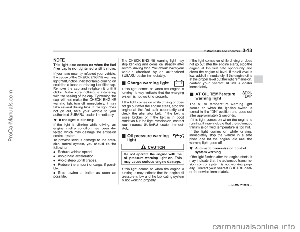
NOTEThis light also comes on when the fuel
filler cap is not tightened until it clicks.
If you have recently refueled your vehicle,
the cause of the CHECK ENGINE warning
light/malfunction indicator lamp coming on
could be a loose or missing fuel filler cap.
Remove the cap and retighten it until it
clicks. Make sure nothing is interfering
with the sealing of the cap. Tightening the
cap will not make the CHECK ENGINE
warning light turn off immediately. It may
take several driving trips. If the light does
not go out, take your vehicle to your
authorized SUBARU dealer immediately.
!If the light is blinking:
If the light is blinking while driving, an
engine misfire condition has been de-
tected which may damage the emission
control system.
To prevent serious damage to the emis-
sion control system, you should do the
following.
. Reduce vehicle speed.
. Avoid hard acceleration.
. Avoid steep uphill grades.
. Reduce the amount of cargo, if possi-
ble.
. Stop towing a trailer as soon as
possible. The CHECK ENGINE warning light may
stop blinking and come on steadily after
several driving trips. You should have your
vehicle checked by an authorized
SUBARU dealer immediately.
&
Charge warning light
If this light comes on when the engine is
running, it may indicate that the charging
system is not working properly.
If the light comes on while driving or does
not go out after the engine starts, stop the
engine at the first safe opportunity and
check the alternator belt. If the belt is
loose, broken or if the belt is in good
condition but the light remains on, contact
your nearest SUBARU dealer immedi-
ately.&
Oil pressure warning
light
CAUTION
Do not operate the engine with the
oil pressure warning light on. This
may cause serious engine damage.
If this light comes on when the engine is
running, it may indicate that the engine oil
pressure is low and the lubricating system
is not working properly. If the light comes on while driving or does
not go out after the engine starts, stop the
engine at the first safe opportunity and
check the engine oil level. If the oil level is
low, add oil immediately. If the engine oil is
at the proper level but the light remains on,
contact your nearest SUBARU dealer
immediately.
&
AT OIL TEMPerature
warning light
The AT oil temperature warning light
comes on when the ignition switch is
turned to the
“ON”position and goes out
after approximately 2 seconds.
If this light comes on when the engine is
running, it may indicate that the automatic
transmission fluid temperature is too hot.
If the light comes on while driving,
immediately stop the vehicle in a safe
place and let the engine idle until the
warning light goes off.
! Automatic transmission control
system warning
If the light flashes after the engine starts, it
may indicate that the automatic transmis-
sion control system is not working prop-
erly. Contact your nearest SUBARU deal-
er for service immediately.
Instruments and controls
3-13
– CONTINUED –
ProCarManuals.com
Page 150 of 409
3-30
Instruments and controls
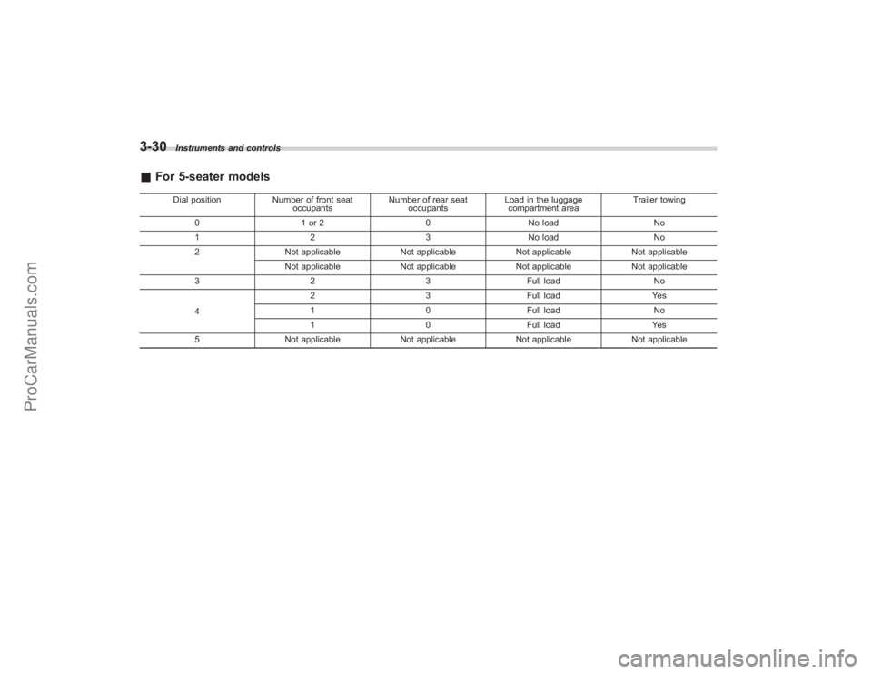
&For 5-seater models
Dial position Number of front seat
occupants Number of rear seat
occupants Load in the luggage
compartment area Trailer towing
0 1 or 2 0No load No
1 23No load No
2 Not applicable Not applicableNot applicable Not applicable
Not applicable Not applicableNot applicable Not applicable
3 23Full load No
4 2
3Full load Yes
1 0Full load No
1 0Full load Yes
5 Not applicable Not applicableNot applicable Not applicable
ProCarManuals.com
Page 151 of 409
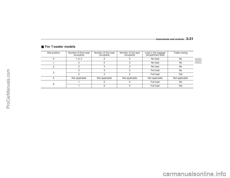
&For 7-seater models
Dial position Number of front seat
occupantsNumber of 2nd seat
occupants Number of 3rd seat
occupants Load in the luggage
compartment area Trailer towing
0 1 or 2 0 0 No load No
1 2 0 2 No load No
2 2 3 2 No load No
3 2 3 2 Full load No
2 3 2 Full load Yes
4 Not applicable Not applicable Not applicable Not applicable Not applicable
5 1 0 0 Full load No
1 0 0 Full load Yes Instruments and controls
3-31
ProCarManuals.com
Page 258 of 409

7-24
Starting and operating
cornering and/or an evasive maneuver,
the Vehicle Dynamics Control system
adjusts the engine’s output and the
wheels’ respective braking forces to help
maintain traction and directional control.
. Traction Control Function
The traction control function is designed to
prevent spinning of the driving wheels on
slippery road surfaces, thereby helping to
maintain traction and directional control.
Activation of this function is shown by
steady illumination of the Vehicle Dy-
namics Control operation indicator light.
. Skid Suppression Function
The skid suppression function is designed
to help maintain directional stability by
suppressing the wheels ’tendency to slide
sideways during steering operations. Acti-
vation of this function is shown by flashing
of the Vehicle Dynamics Control operation
indicator light.NOTE. Slight twitching of the brake pedal
may be felt when the Vehicle Dynamics
Control system operates; a small de-
gree of vehicle or steering wheel shak-
ing may also be noticed in this situa-
tion. These are normal characteristics
of Vehicle Dynamics Control operation
and are no cause for alarm.
. When driving off immediately after starting the engine, a short operation
noise may be noticed coming from the
engine compartment. This noise is
generated as a result of a check being
performed on the Vehicle Dynamics
Control system and is normal.
.
Depending on the timing of activa-
tion of the brakes, the brake pedal may
seem to jolt when you drive off after
starting the engine. This is a conse-
quence of the Vehicle Dynamics Con-
trol operational check and is normal.
. In the circumstances listed in the
following, the vehicle may be more
unstable than it feels to the driver.
The Vehicle Dynamics Control System
may therefore operate. Such operation
does not indicate a system fault.
.on gravel-covered or rutted roads
. on unfinished roads
. when the vehicle is towing a
trailer
. when the vehicle is fitted with
snow tires or winter tires
. Activation of the Vehicle Dynamics
Control system will cause operation of
the steering wheel to feel slightly
different compared to that for normal
conditions.
. Even if the vehicle is equipped with
a Vehicle Dynamics Control system, it
is important that winter tires be used when driving on snow-covered or icy
roads. (All four wheels should be fitted
with tires of the same size and brand).
Furthermore, if snow chains are to be
used, they should be fitted on the front
wheels. When a vehicle is fitted with
snow chains, however, the effective-
ness of the Vehicle Dynamics Control
system is reduced and this should be
taken into account when driving the
vehicle in such a condition.
.
It is always important to reduce
speed when approaching a corner,
even if the vehicle is equipped with
Vehicle Dynamics Control.
. All four wheels should be fitted with
tires of the same size, type, and brand;
furthermore, the amount of wear
should be the same for all four tires. If
these precautions are not observed
and non-matching tires are used, it is
quite possible that the Vehicle Dy-
namics Control system will be unable
to operate correctly as intended.
. Always turn off the engine before
replacing a tire as failure to do so may
render the Vehicle Dynamics Control
system unable to operate correctly.
ProCarManuals.com
Page 269 of 409

New vehicle break-in driving–the first
1,000 miles (1,600 km) .................................. 8-2
Fuel economy hints ......................................... 8-2
Engine exhaust gas (Carbon monoxide) ........ 8-2
Catalytic converter ........................................... 8-3
Periodic inspections ........................................ 8-4
Driving in foreign countries ............................ 8-4
Driving tips for AWD vehicles ......................... 8-4
On-pavement and off road driving .................. 8-5
Winter driving ................................................... 8-7
Operation during cold weather .......................... 8-7
Driving on snowy and icy roads ....................... 8-9
Corrosion protection ...................................... 8-10
Snow tires ..................................................... 8-10
Tire chains ...................................................... 8-11
Rocking the vehicle ......................................... 8-11
Loading your vehicle ...................................... 8-11
Vehicle capacity weight ................................... 8-12
GVWR and GAWR (Gross Vehicle Weight Rating and Gross Axle Weight Rating) ..................... 8-12
Roof rails and crossbar (if equipped) ............... 8-13
Roof molding and crossbar (if equipped) ......... 8-16
Trailer hitch (if equipped).............................. 8-18
Connecting a trailer........................................ 8-18
When you do not tow a trailer .. ....................... 8-20
Trailer towing................................................. 8-20
Warranties and maintenance ........................... 8-20
Maximum load limits ....................................... 8-20
Trailer hitches ................................................. 8-23
Connecting a trailer ........................................ 8-24
Trailer towing tips ........................................... 8-26
Driving tips
8
ProCarManuals.com
Page 280 of 409
8-12
Driving tips
CAUTION
Do not carry spray cans, containers
with flammable or corrosive liquids
or any other dangerous items inside
the vehicle.NOTEFor better fuel economy, do not carry
unneeded cargo.&Vehicle capacity weight
The load capacity of your vehicle is
determined by weight, not by available
cargo space. The maximum load you can
carry in your vehicle is shown on the
vehicle placard attached to the driver ’s
side door pillar. It includes the total weight
of the driver and all passengers and their
belongings, any optional equipment such
as a trailer hitch, roof rack or bike carrier,
etc., and the tongue load of a trailer.
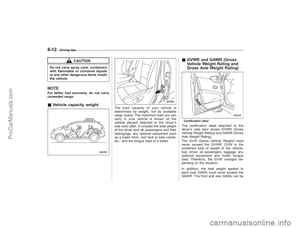
& GVWR and GAWR (Gross
Vehicle Weight Rating and
Gross Axle Weight Rating)Certification labelThe certification label attached to the
driver ’s side door shows GVWR (Gross
Vehicle Weight Rating) and GAWR (Gross
Axle Weight Rating).
The GVW (Gross Vehicle Weight) must
never exceed the GVWR. GVW is the
combined total of weight of the vehicle,
fuel, driver, all passengers, luggage, any
optional equipment and trailer tongue
load. Therefore, the GVW changes de-
pending on the situation.
In addition, the total weight applied to
each axle (GAW) must never exceed the
GAWR. The front and rear GAWs can be
ProCarManuals.com
Page 286 of 409
8-18
Driving tips
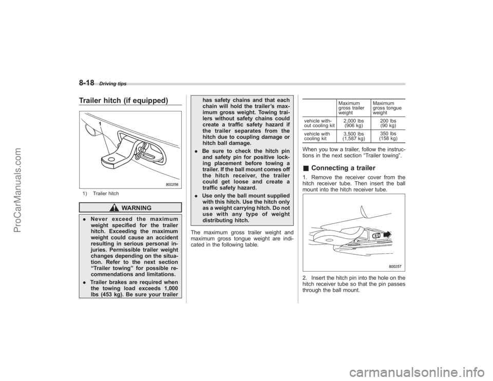
Trailer hitch (if equipped)1) Trailer hitch
WARNING
.Never exceed the maximum
weight specified for the trailer
hitch. Exceeding the maximum
weight could cause an accident
resulting in serious personal in-
juries. Permissible trailer weight
changes depending on the situa-
tion. Refer to the next section
“ Trailer towing” for possible re-
commendations and limitations.
. Trailer brakes are required when
the towing load exceeds 1,000
lbs (453 kg). Be sure your trailer has safety chains and that each
chain will hold the trailer
’s max-
imum gross weight. Towing trai-
lers without safety chains could
create a traffic safety hazard if
the trailer separates from the
hitch due to coupling damage or
hitch ball damage.
. Be sure to check the hitch pin
and safety pin for positive lock-
ing placement before towing a
trailer. If the ball mount comes off
the hitch receiver, the trailer
could get loose and create a
traffic safety hazard.
. Use only the ball mount supplied
with this hitch. Use the hitch only
as a weight carrying hitch. Do not
use with any type of weight
distributing hitch.
The maximum gross trailer weight and
maximum gross tongue weight are indi-
cated in the following table.
Maximum
gross trailer
weight Maximum
gross tongue
weight
vehicle with-
out cooling kit 2,000 lbs
(906 kg) 200 lbs
(90 kg)
vehicle with
cooling kit 3,500 lbs
(1,587 kg) 350 lbs
(158 kg)
When you tow a trailer, follow the instruc-
tions in the next section “Trailer towing”.& Connecting a trailer1. Remove the receiver cover from the
hitch receiver tube. Then insert the ball
mount into the hitch receiver tube.2. Insert the hitch pin into the hole on the
hitch receiver tube so that the pin passes
through the ball mount.
ProCarManuals.com
Page 287 of 409
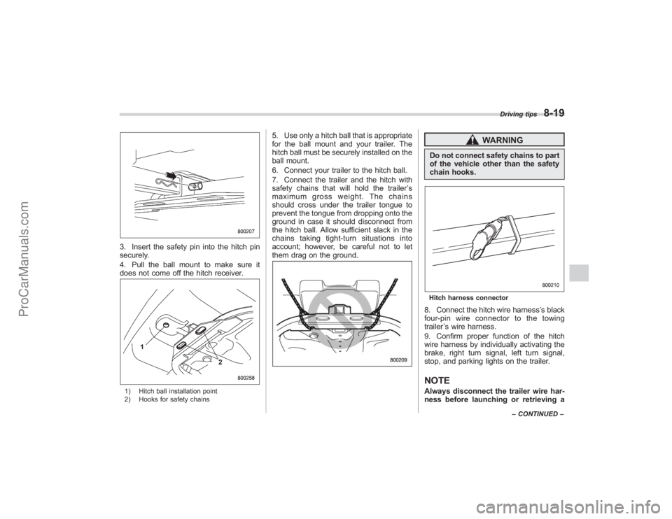
3. Insert the safety pin into the hitch pin
securely.
4. Pull the ball mount to make sure it
does not come off the hitch receiver.1) Hitch ball installation point
2) Hooks for safety chains
5. Use only a hitch ball that is appropriate
for the ball mount and your trailer. The
hitch ball must be securely installed on the
ball mount.
6. Connect your trailer to the hitch ball.
7. Connect the trailer and the hitch with
safety chains that will hold the trailer’s
maximum gross weight. The chains
should cross under the trailer tongue to
prevent the tongue from dropping onto the
ground in case it should disconnect from
the hitch ball. Allow sufficient slack in the
chains taking tight-turn situations into
account; however, be careful not to let
them drag on the ground.
WARNING
Do not connect safety chains to part
of the vehicle other than the safety
chain hooks.Hitch harness connector8. Connect the hitch wire harness ’s black
four-pin wire connector to the towing
trailer ’s wire harness.
9. Confirm proper function of the hitch
wire harness by individually activating the
brake, right turn signal, left turn signal,
stop, and parking lights on the trailer.NOTEAlways disconnect the trailer wire har-
ness before launching or retrieving a
Driving tips
8-19
– CONTINUED –
ProCarManuals.com