2008 SUBARU TRIBECA fuse
[x] Cancel search: fusePage 17 of 409

&Instrument panel
1) Door locks (page 2-4)
2) Illumination brightness control
(page 3-28)
3) Remote control mirror (page 3-40) Power folding mirror switch (if equipped)
(page 3-41)
4) Windshield wiper deicer (page 3-36)
5) Traction Control system OFF switch (page 7-26)
6) Headlight beam leveler (if equipped) (page 3-29)
7) Light control lever (page 3-26)
8) Combination meter (page 3-5)
9) Wiper control lever (page 3-33)
10) Cruise control (page 7-30)
11) Horn (page 3-42)
12) SRS airbag (page 1-44)
13) Tilt steering (page 3-41)
14) Hood lock release knob (page 11-4)
15) Fuse box (page 11-38)
16) Power windows (page 2-19)
15
– CONTINUED –
ProCarManuals.com
Page 98 of 409

2-4
Keys and doors
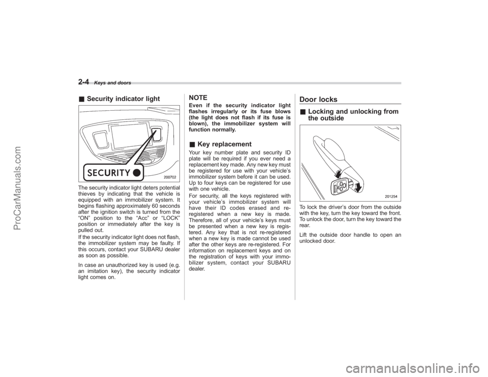
&Security indicator lightThe security indicator light deters potential
thieves by indicating that the vehicle is
equipped with an immobilizer system. It
begins flashing approximately 60 seconds
after the ignition switch is turned from the
“ON ”position to the “Acc”or “LOCK ”
position or immediately after the key is
pulled out.
If the security indicator light does not flash,
the immobilizer system may be faulty. If
this occurs, contact your SUBARU dealer
as soon as possible.
In case an unauthorized key is used (e.g.
an imitation key), the security indicator
light comes on.
NOTEEven if the security indicator light
flashes irregularly or its fuse blows
(the light does not flash if its fuse is
blown), the immobilizer system will
function normally.& Key replacementYour key number plate and security ID
plate will be required if you ever need a
replacement key made. Any new key must
be registered for use with your vehicle’ s
immobilizer system before it can be used.
Up to four keys can be registered for use
with one vehicle.
For security, all the keys registered with
your vehicle ’s immobilizer system will
have their ID codes erased and re-
registered when a new key is made.
Therefore, all of your vehicle’ s keys must
be presented when a new key is regis-
tered. Any key that is not re-registered
when a new key is made cannot be used
after the other keys are re-registered. For
information on replacement keys and on
the registration of keys with your immo-
bilizer system, contact your SUBARU
dealer.
Door locks& Locking and unlocking from
the outsideTo lock the driver ’s door from the outside
with the key, turn the key toward the front.
To unlock the door, turn the key toward the
rear.
Lift the outside door handle to open an
unlocked door.
ProCarManuals.com
Page 127 of 409

The odometer/trip meter will also go off if
you open and close the driver’sdoor
within 10 seconds of illumination of the
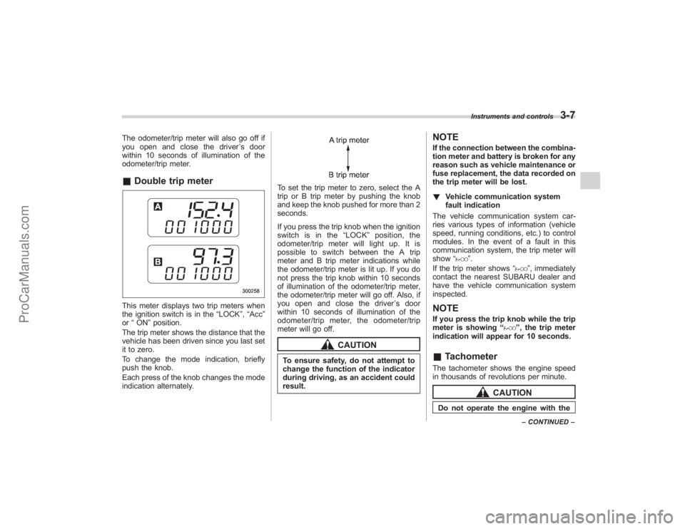
odometer/trip meter.& Double trip meterThis meter displays two trip meters when
the ignition switch is in the “LOCK”,“Acc ”
or “ON ”position.
The trip meter shows the distance that the
vehicle has been driven since you last set
it to zero.
To change the mode indication, briefly
push the knob.
Each press of the knob changes the mode
indication alternately.
To set the trip meter to zero, select the A
trip or B trip meter by pushing the knob
and keep the knob pushed for more than 2
seconds.
If you press the trip knob when the ignition
switch is in the “LOCK ”position, the
odometer/trip meter will light up. It is
possible to switch between the A trip
meter and B trip meter indications while
the odometer/trip meter is lit up. If you do
not press the trip knob within 10 seconds
of illumination of the odometer/trip meter,
the odometer/trip meter will go off. Also, if
you open and close the driver ’sdoor
within 10 seconds of illumination of the
odometer/trip meter, the odometer/trip
meter will go off.
CAUTION
To ensure safety, do not attempt to
change the function of the indicator
during driving, as an accident could
result.
NOTEIf the connection between the combina-
tion meter and battery is broken for any
reason such as vehicle maintenance or
fuse replacement, the data recorded on
the trip meter will be lost.
! Vehicle communication system
fault indication
The vehicle communication system car-
ries various types of information (vehicle
speed, running conditions, etc.) to control
modules. In the event of a fault in this
communication system, the trip meter will
show “
”.
If the trip meter shows “
”, immediately
contact the nearest SUBARU dealer and
have the vehicle communication system
inspected.
NOTEIf you press the trip knob while the trip
meter is showing “
”, the trip meter
indication will appear for 10 seconds.
& TachometerThe tachometer shows the engine speed
in thousands of revolutions per minute.
CAUTION
Do not operate the engine with the
Instruments and controls
3-7
–CONTINUED –
ProCarManuals.com
Page 229 of 409

Rear view camera (if
equipped)When the ignition switch is“ON”and the
selector lever is set to “R”, the rear view
camera automatically displays the rear
view image from the vehicle.
WARNING
. Since the rear view camera uses
a wide-angle lens, the image on
the monitor is different from the
actual view in terms of distance.
. Since the range of the image on
the monitor is limited, you should
always check the rear view with
your eyes and move backward at
a slow speed.
. Do not disassemble or modify the
camera, switch or wiring. If
smoke comes out or you smell
a strange odor, stop using the
rear view camera immediately.
Contact your Subaru dealer for
an inspection. Continued use
may result in accident, fire or
electric shock.
CAUTION
. If your vehicle is washed with a
high-pressure washer, do not
allow water to contact the camera
directly. Entry of water in the
camera lens may result in con-
densation, malfunction, fire or
electric shock.
. Since the camera is a precision
device, do not subject it to strong
impacts. Otherwise, malfunction,
fire or electric shock may occur.
. If mud or snow sticks to or is
frozen on the camera, you must
be very careful removing it.
Otherwise, damage done to the
camera may cause a fire or
electric shock. Pour lukewarm
water over the camera to remove
mud or ice.
. Do not put a flame close to the
camera or wiring. Otherwise, da-
mage or fire may occur.
. When replacing the fuse, be sure
to use a fuse with the specified
rating. Use of a fuse with a
different rating may result in a
malfunction.
. If the rear view camera is used for
a long time while the engine is not operated, the battery may
become completely discharged.
NOTE.
Do not wipe the camera with alcohol,
benzine or paint thinner. Otherwise,
discoloration may occur. To remove
contamination, wipe the camera with a
cloth moistened with a diluted neutral
detergent and then wipe it with a dry
cloth.
. When waxing the vehicle, be careful
not to apply the wax to the camera. If it
comes in contact with the camera,
moisten a clean cloth with a diluted
neutral detergent to remove the wax.
. The camera lens has hard coating to
help prevent scratches. However, when
washing the vehicle or cleaning the
camera lens, be careful not to scratch
the camera lens. Do not use a washing
brush directly on the camera lens. The
monitor screen may be adversely af-
fected.
. Strong light shined on the camera
lens may develop white light stripes
around the light source. This is not a
malfunction.
Interior equipment
6-21
– CONTINUED –
ProCarManuals.com
Page 241 of 409

Preparing to driveYou should perform the following checks
and adjustments every day before you
start driving.
1. Check that all windows, mirrors, and
lights are clean and unobstructed.
2. Check the appearance and condition
of the tires. Also check tires for proper
inflation.
3. Look under the vehicle for any sign of
leaks.
4. Check that the hood and rear gate are
fully closed.
5. Check the adjustment of the seat.
6. Check the adjustment of the inside
and outside mirrors.
7. Fasten your seatbelt. Check that your
passengers have fastened their seatbelts.
8. Check the operation of the warning
and indicator lights when the ignition
switch is turned to the“ON”position.
9. Check the gauges, indicator and warn-
ing lights after starting the engine.NOTEEngine oil, engine coolant, brake fluid,
washer fluid and other fluid levels
should be checked daily, weekly or at
fuel stops.
Starting the engine
CAUTION
. Do not operate the starter motor
continuously for more than 10
seconds. If the engine fails to
start after operating the starter
for 5 to 10 seconds, wait for 10
seconds or more before trying
again.
. If you restart the engine while the
vehicle is moving, shift the se-
lector lever into the “N ” position.
Do not attempt to place the
selector lever of a moving vehicle
into the “P ” position.
1. Apply the parking brake.
2. Turn off unnecessary lights and ac-
cessories.
3. Shift the selector lever to the “P”or “N”
position (preferably “P ” position). The
starter will only operate when the select
lever is at the “P”or “N”position.
4. Turn the ignition switch to the “ON”
position and check the operation of the
warning and indicator lights. Refer to the
“ Warning and indicator lights ”section
(chapter 3).
5. Turn the ignition switch to the “START”position
without depressing the accelera-
tor pedal. Release the key immediately
after the engine has started.
If the engine does not start, try the
following.
(1) Turn the ignition switch to the
“LOCK ”position and wait for at least
10 seconds. After checking that the
parking brake is firmly set, turn the
ignition switch to the “START”position
while depressing the accelerator pedal
slightly (approximately a quarter of the
full stroke). Release the accelerator
pedal as soon as the engine starts.
(2) If this fails to start the engine, turn
the ignition switch back to the “LOCK”
position and wait for at least 10
seconds. Then fully depress the accel-
erator pedal and turn the ignition
switch to the “START”position. If the
engine starts, quickly release the
accelerator pedal.
(3) If this fails to start the engine, turn
the ignition switch again to the “LOCK”
position. After waiting for 10 seconds
or longer, turn the ignition switch to the
“START ”position without depressing
the accelerator pedal.
(4)
If the engine still refuses to start,
contact your nearest SUBARU dealer
for assistance.
6. Confirm that all warning and indicator
Starting and operating
7-7
– CONTINUED –
ProCarManuals.com
Page 244 of 409

7-10
Starting and operating
transmitter within a few seconds immedi-
ately following remote engine start shut-
down.&Pre-heating or pre-cooling
the interior of the vehicleBefore exiting the vehicle, set the tem-
perature controls to the desired setting
and operation. After the system starts the
vehicle, the heater or air-conditioning will
activate and heat or cool the interior to
your setting.&Service modeIn service mode, the remote start function
is temporarily disabled to prevent the
system from unexpectedly starting the
engine while being serviced.
! To engage the service mode
Turn the ignition switch to the “ON ”
position, depress and hold the brake pedal
then, press and release the “
”button on
the remote control transmitter three times.
The system will pause for 1 second and
then flash the parking lights and honk the
horn three times indicating that the system
is in service mode. When attempting to
activate the remote start system while in
service mode, the parking lights will flash
and the horn will honk two times and will
not start. !
To disengage the service mode
Turn the ignition switch to the “ON ”
position, depress and hold the brake
pedal, then press and release the “
”
button on the remote control transmitter
three times. The system will pause for 1
second and flash the parking lights one
time indicating that the system has exited
service mode.
NOTEWhen taking your vehicle in for service,
it is recommended that you inform the
service personnel that your vehicle is
equipped with a remote control start
system.& Remote transmitter program-
ming and programmable fea-
ture optionNew transmitters can be programmed to
the engine starter system in the event that
remote transmitters are lost, stolen or
damaged. The remote engine start system
also has one programmable feature that
can be adjusted for user preference.
The remote engine starter system can be
programmed to either make an audible
horn chirp upon remote start activation or
not. Remote transmitter programming and
feature programming can be adjusted
using the following procedure. 1. Open the driver
’s door (the driver ’s
door must remain opened throughout the
entire process).
2. Insert the key into the vehicle’ s ignition
switch and turn to the “ON”position.
3. Locate the small black programming
button behind the fuse box cover, on the
driver ’s side left under the dashboard
panel.
4. Press and hold the black programming
button for 10 to 15 seconds. The horn will
honk and the parking lights will flash three
times to indicate that the system has
entered programming mode. At this point
you can perform either action (Step 5 or
Step 6).
5. To program a remote transmitter:
press and release the “
”button on each
transmitter. The horn will honk and the
parking lights will flash one time to indicate
a successful transmitter learn each time
the “
”button is pressed. You can
program up to eight transmitters.
6. To toggle the Horn Confirmation chirps
ON/OFF: press and release the brake to
toggle the feature. The horn will chirp and
the parking lights will flash one time to
indicate Confirmation Horn Chirps are
“OFF ”. The horn will honk and the parking
lights will flash 2 times to indicate Con-
firmation Horn Chirps are “ON”. Pressing
the brake pedal repeatedly will toggle the
ProCarManuals.com
Page 324 of 409

Maintenance and serviceReplacement of wiper blades...................... 11-33
Windshield wiper blade assembly .................. 11-33
Windshield wiper blade rubber ...................... 11-34
Rear window wiper blade assembly ............... 11-35
Rear window wiper blade rubber .................... 11-35
Battery........................................................... 11-37
Fuses ............................................................ 11-38
Main fuse ...................................................... 11-39
Installation of accessories ........................... 11-40
Replacing bulbs ........................................... 11-41
Headlights (Vehicles with HID headlights) ...... 11-42
Headlights (Vehicles without HID headlights) .................................................. 11-43
Parking light (right-hand side) ........................ 11-44 Front turn signal light (right-hand side)
......... 11-45
Front fog light ............................................... 11-45
Rear combination lights ................................ 11-46
Back-up light/Tail light .................................. 11-47
Rear gate light .............................................. 11-47
License plate light ........................................ 11-47
Dome light .................................................... 11-48
Map light ...................................................... 11-49
Vanity mirror light ......................................... 11-49
Door step light .............................................. 11-50
Cargo area light ............................................ 11-50
ProCarManuals.com
Page 328 of 409

11-6
Maintenance and service
Engine compartment overview
1) Air cleaner element (page 11-14)
2) Power steering fluid reservoir(page 11-19)
3) Differential gear oil level gauge (page 11-17)
4) Automatic transmission fluid level gauge (page 11-15)
5) Brake fluid reservoir (page 11-20)
6) Fuse box (page 11-38)
7) Battery (page 11-37)
8) Windshield washer tank (page 11-32)
9) Radiator cap (page 11-11)
10) Engine oil filler cap (page 11-7)
11) Engine coolant reservoir (page 11-11)
12) Engine oil level gauge (page 11-7)
ProCarManuals.com