Page 54 of 260

Cockpit
52Rev counter
The rev. counter displays the engine speed in revolutions per
minute.The start of the red zone ⇒page 51, fig. 30 indicates the maximum
engine speed operating at service temperature. However, it is advisable to
change up a into a higher gear, move the selector lever to D or lift your foot
off the accelerator before the needle reaches the red zone.
Caution
The rev counter needle must never enter the red zone on the scale. Risk of
engine damage.
For the sake of the environment
Changing up into higher gears early will help you to save fuel and minimise
engine noise.SpeedometerThe speedometer is equipped with a digital odometer and a trip counter, in
addition to a service intervals display.
During the running-in period, the instructions shown on ⇒page 153 should
be followed.
Digital display in the instrument panelFuel gauge
and reserve indicator
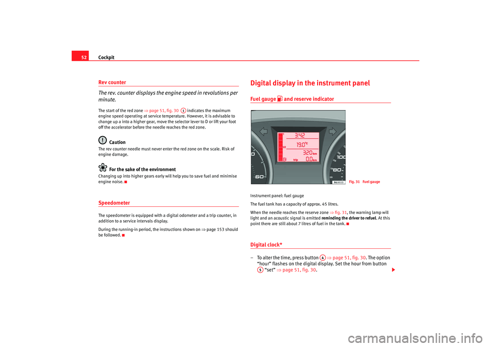
Instrument panel: fuel gauge
The fuel tank has a capacity of approx. 45 litres.
When the needle reaches the reserve zone ⇒fig. 31 , the warning lamp will
light and an acoustic signal is emitted reminding the driver to refuel. At this
point there are still about 7 litres of fuel in the tank.Digital clock* – To alter the time, press button ⇒page 51, fig. 30 . The option
“hour” flashes on the digital display. Set the hour from button “set” ⇒ page 51, fig. 30 .
A1
Fig. 31 Fuel gauge
A4
A5
Ibiza250_angles Seite 52 Dienstag, 5. August 2008 1:11 13
Page 58 of 260

Cockpit
56Mileage display or Service Interval DisplayDistance display
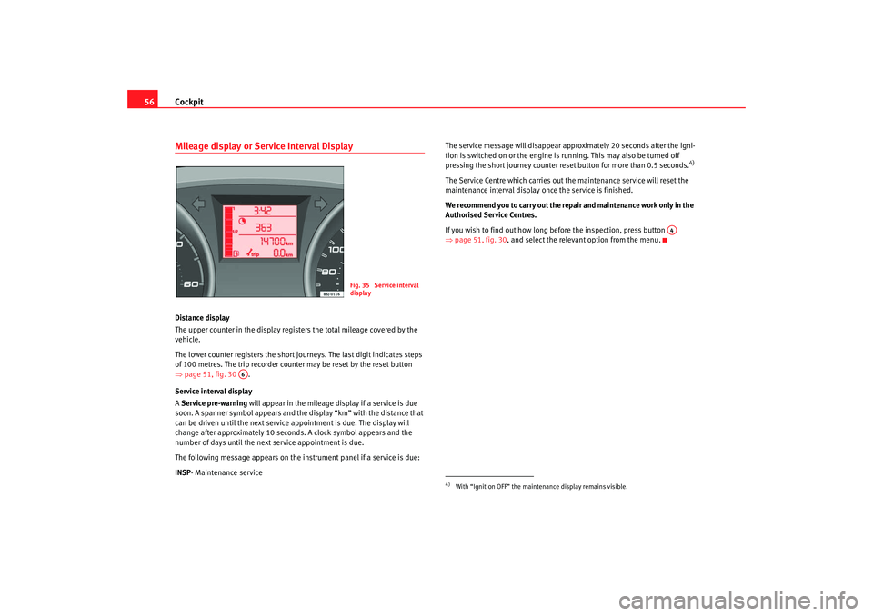
The upper counter in the display registers the total mileage covered by the
vehicle.
The lower counter registers the short journeys. The last digit indicates steps
of 100 metres. The trip recorder counter may be reset by the reset button
⇒ page 51, fig. 30 .
Service interval display
A Service pre-warning will appear in the mileage display if a service is due
soon. A spanner symbol appears and the display “km” with the distance that
can be driven until the next service appointment is due. The display will
change after approximately 10 seconds. A clock symbol appears and the
number of days until the next service appointment is due.
The following message appears on the instrument panel if a service is due:
INSP - Maintenance service The service message will disappear approximately 20 seconds after the igni-
tion is switched on or the engine is
running. This may also be turned off
pressing the short journey counter reset button for more than 0.5 seconds.
4)
The Service Centre which carries out the maintenance service will reset the
maintenance interval display once the service is finished.
We recommend you to carry out the re pair and maintenance work only in the
Authorised Service Centres.
If you wish to find out how long before the inspection, press button
⇒ page 51, fig. 30, and select the relevant option from the menu.
Fig. 35 Service interval
display
A6
4)With “Ignition OFF” the mainte nance display remains visible.
A4
Ibiza250_angles Seite 56 Dienstag, 5. August 2008 1:11 13
Page 121 of 260

Heating, Ventilation and Air conditioning 119
Safety First
Operating instructions
Practical tips
Te c h n i c a l D a t a
•
In air recirculation mode, no cold ai r from the outside enters the vehicle
interior. The windows can quickly fog over if the heating is switched off.
Therefore, never leave the air recircul ation mode switched on for a long
time (risk of accident).Note
•
Please consider the general notes ⇒page 127.
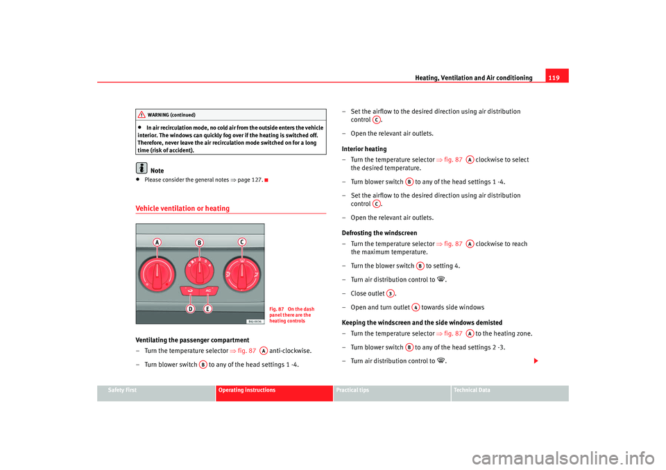
Vehicle ventilation or heatingVentilating the passenger compartment
– Turn the temperature selector ⇒ fig. 87 anti-clockwise.
– Turn blower switch to any of the head settings 1 -4. – Set the airflow to the desired direction using air distribution
control .
– Open the relevant air outlets.
Interior heating
– Turn the temperature selector ⇒ fig. 87 clockwise to select
the desired temperature.
– Turn blower switch to any of the head settings 1 -4.
– Set the airflow to the desired direction using air distribution control .
– Open the relevant air outlets.
Defrosting the windscreen
– Turn the temperature selector ⇒ fig. 87 clockwise to reach
the maximum temperature.
– Turn the blower switch to setting 4.
– Turn air distribution control to
.
–Close outlet .
– Open and turn outlet towards side windows
Keeping the windscreen and the side windows demisted
– Turn the temperature selector ⇒ fig. 87 to the heating zone.
– Turn blower switch to any of the head settings 2 -3.
– Turn air distribution control to
.
WARNING (continued)
Fig. 87 On the dash
panel there are the
heating controls
AA
AB
AC
AA
AB
AC
AA
AB
A3
A4
AA
AB
Ibiza250_angles Seite 119 Dienstag, 5. August 2008 1:11 13