2008 RENAULT SCENIC ignition
[x] Cancel search: ignitionPage 75 of 128

AUTOMATIC TRANSMISSION
Fault finding – Conformity check23A
23A - 75V4 MR-372-J84-23A050$462.mif
SIEMENS TA2000
Vdiag No.: 10-11-15
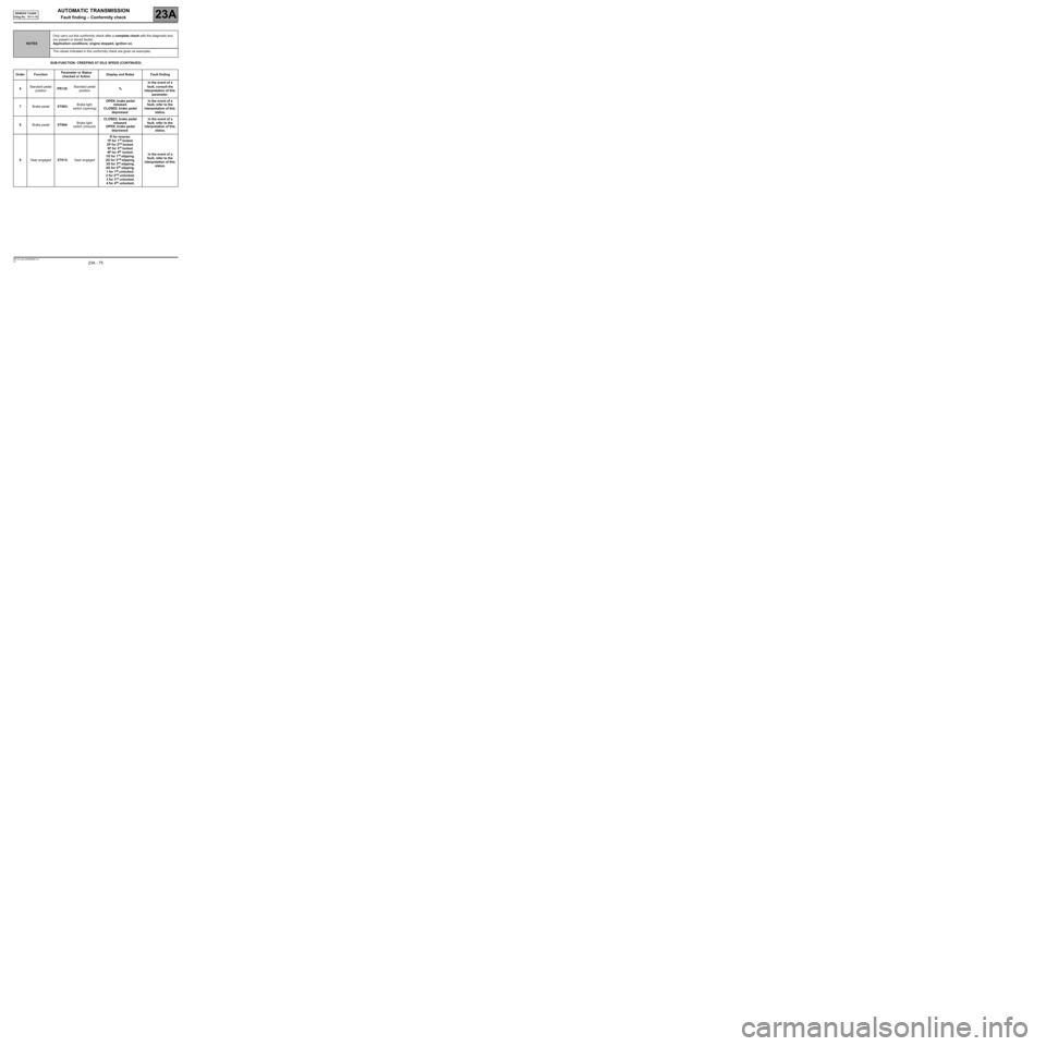
SUB-FUNCTION: CREEPING AT IDLE SPEED (CONTINUED)
NOTESOnly carry out this conformity check after a complete check with the diagnostic tool
(no present or stored faults).
Application conditions: engine stopped, ignition on.
The values indicated in this conformity check are given as examples.
Order FunctionParameter or Status
checked or ActionDisplay and Notes Fault finding
6Standard pedal
positionPR135:Standard pedal
position% In the event of a
fault, consult the
interpretation of this
parameter.
7Brake pedalET003:Brake light
switch (opening)OPEN, brake pedal
released.
CLOSED, brake pedal
depressed.In the event of a
fault, refer to the
interpretation of this
status.
8Brake pedalET004:Brake light
switch (closure)CLOSED, brake pedal
released.
OPEN, brake pedal
depressed.In the event of a
fault, refer to the
interpretation of this
status.
9Gear engagedET013:Gear engagedR for reverse.
1P for 1
st locked.
2P for 2nd locked.
3P for 3rd locked.
4P for 4th locked.
1G for 1st slipping.
2G for 2nd slipping.
3G for 3rd slipping.
4G for 4th slipping.
1 for 1st unlocked.
2 for 2nd unlocked.
3 for 3rd unlocked.
4 for 4th unlocked.In the event of a
fault, refer to the
interpretation of this
status.
Page 106 of 128

AUTOMATIC TRANSMISSION
Fault finding – Parameter interpretation23A
23A - 106V4 MR-372-J84-23A050$726.mif
SIEMENS TA2000
Vdiag No.: 10-11-15
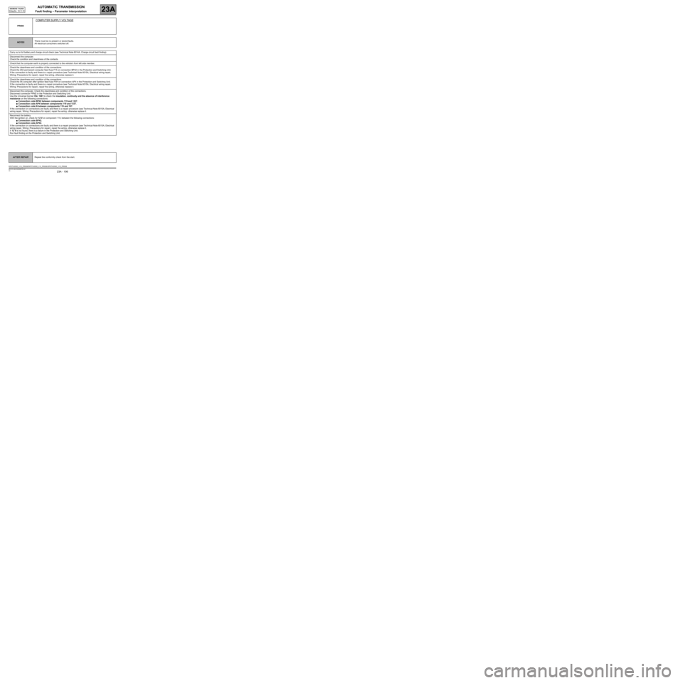
PR008
COMPUTER SUPPLY VOLTAGE
NOTESThere must be no present or stored faults.
All electrical consumers switched off.
Carry out a full battery and charge circuit check (see Technical Note 6014A, Charge circuit fault finding).
Disconnect the computer.
Check the condition and cleanliness of the contacts.
Check that the computer earth is properly connected to the vehicle's front left side member.
Check the cleanliness and condition of the connections.
Check the 20A permanent computer feed fuse F15 on connection BP42 in the Protection and Switching Unit.
If the connection is faulty and there is a repair procedure (see Technical Note 6015A, Electrical wiring repair,
Wiring: Precautions for repair), repair the wiring, otherwise replace it.
Check the cleanliness and condition of the connections.
Check the 5A computer after ignition feed fuse F5H on connection AP4 in the Protection and Switching Unit.
If the connection is faulty and there is a repair procedure (see Technical Note 6015A, Electrical wiring repair,
Wiring: Precautions for repair), repair the wiring, otherwise replace it.
Disconnect the computer. Check the cleanliness and condition of the connections.
Disconnect connector PPM2 in the Protection and Switching Unit.
Use the Universal bornier Elé. 1681 to check the insulation, continuity and the absence of interference
resistance on the following connections:
●Connection code BP42 between components 119 and 1337.
●Connection code AP4 between components 119 and 1337.
●Connection code N between components 119 and 107.
If the connection or connections are faulty and there is a repair procedure (see Technical Note 6015A, Electrical
wiring repair, Wiring: Precautions for repair), repair the wiring, otherwise replace it.
Reconnect the battery.
With the ignition on, check for 12 V on component 119, between the following connections:
●Connection code BP42.
●Connection code AP42.
If the connection or connections are faulty and there is a repair procedure (see Technical Note 6015A, Electrical
wiring repair, Wiring: Precautions for repair), repair the wiring, otherwise replace it.
If 12 V is not found, there is a failure in the Protection and Switching Unit.
Run fault finding on the Protection and Switching Unit.
AFTER REPAIRRepeat the conformity check from the start.
DP0TA2000_V10_PR008/DP0TA2000_V11_PR008 /DP0TA2000_V15_PR008
Page 113 of 128

AUTOMATIC TRANSMISSION
Fault finding – Dealing with command modes23A
23A - 113V4 MR-372-J84-23A050$792.mif
SIEMENS TA2000
Vdiag No.: 10-11-15
AC024
ACTUATOR SEQUENTIAL CONTROL
NOTESCheck the 20A permanent computer feed fuse marked 15 in the Protection and
Switching Unit. Check the cleanliness and condition of the connections.
Check the 5A after-ignition computer feed fuse marked 5H in the Protection and
Switching Unit.
Replace the fuses if necessary.
Check the cleanliness and condition of the connections.
Engine speed zero and gear lever in position P or N.
If the solenoid valves are not activated, check:
–the gearbox oil level,
–the cleanness and condition of the computer connector and modular connector,
Check the insulation, continuity and absence of interference resistance on the following connections:
●Connection code 5AU between components 119 and 754.
●Connection code 5AV between components 119 and 754.
●Connection code 5AW between components 119 and 754.
●Connection code 5AX between components 119 and 754.
●Connection code 5AY between components 119 and 754.
●Connection code 5DL between components 119 and 754.
●Connection code 5DM between components 119 and 754.
●Connection code 5BA between components 119 and 754.
●Connection code 5AZ, between components 119 and 754.
●Connection code 5DD between components 119 and 1019.
●Connection code 5DN between components 119 and 1019.
If the fault is still present, contact the Techline.
AFTER REPAIRRepeat the conformity check from the start.
DP0TA2000_V10_ACO24/DP0TA2000_V11_AC024 /DP0TA2000_V15_AC024
Page 115 of 128

AUTOMATIC TRANSMISSION
23A
23A-115V4 MR-372-J84-23A050$924.mif
SIEMENS TA2000
Vdiag No.: 10-11-15AUTOMATIC TRANSMISSION
Fault finding – Fault Finding Chart
ALP1 No dialogue with the computer
NOTESNone.
Try the diagnostic tool on another vehicle.
Check:
–the connection between the diagnostic tool and the diagnostic socket (connection and cable in good condition),
–the power supply to the computer,
–the engine and passenger compartment fuses.
Check that the CLIP sensor is supplied by connections BP32, MAN and NAM of component 225, displayed when
both red indicator lights on the sensor illuminate.
Make sure that the CLIP sensor is connected to the computer's USB port.
Make sure the CLIP sensor is communicating properly with the vehicle's computers; this can be seen by the two
green diodes on the sensor lighting up.
Check the following connections on component 225:
●Connection code AP43 (+ after ignition feed).
●Connection code BP32 (+ battery).
●Connection code MAN (earth).
If the connection or connections are faulty and there is a repair procedure (see Technical Note 6015A,
Electrical wiring repair, Wiring: Precautions for repair), repair the wiring, otherwise replace it.
No communication on line K
Check the continuity, insulation and absence of interference resistance on line K of the diagnostic socket.
Disconnect the automatic transmission computer connector to check the insulation, continuity and the absence
of interference resistance of the following connections:
●Connection code AP4 between components 119 and 1337.
●Connection code BP42 between components 119 and 1337.
●Connection code N between components 119 and 107.
●Connection code 3HK between components 119 and 225.
If the connection or connections are faulty and there is a repair procedure (see Technical Note 6015A,
Electrical wiring repair, Wiring: Precautions for repair), repair the wiring, otherwise replace it.
If the fault is still present, contact the Techline.
AFTER REPAIRCarry out a road test followed by a complete check with the diagnostic tool.
DP0TA2000_V10_ALP1/DP0TA2000_V11_ALP1/DP0TA2000_V15_ALP1
MR-372-J84-23A050$924.mif
Page 116 of 128

AUTOMATIC TRANSMISSION
Fault finding – Fault Finding Chart23A
23A-116V4 MR-372-J84-23A050$924.mif
SIEMENS TA2000
Vdiag No.: 10-11-15
ALP2 Engine starting faults
NOTESOnly refer to Customer complaints after carrying out a complete fault finding
procedure with the diagnostic tool and the conformity check.
Make sure that the diagnostic tool report, gear lever positions and instrument panel all indicate the same gear
engaged.
Adjust the gear lever cable if it is faulty.
The engine will only start when the gear lever is in the P or N position.
Check the battery charge and the condition of the terminals (oxidation).
Check the multifunction switch mounting and that it is working.
Check the gear lever control cable and adjust if necessary (see MR 364 Mechanical, 23A, Automatic
transmission, Filling-Levels (for Mégane II) and MR 370 Mechanical, 23A, Automatic transmission,
Draining-Filling (for Scénic II)).
Ensure that the ignition switch is working properly.
Check the power circuit of the starter relay and the starter.
Carry out fault finding on the injection system.
If the engine still doesn't start, contact the Techline.
AFTER REPAIRCarry out a road test followed by a complete check with the diagnostic tool.
DP0TA2000_V10_ALP2/DP0TA2000_V11_ALP2/DP0TA2000_V15_ALP2
Page 117 of 128

AUTOMATIC TRANSMISSION
Fault finding – Fault Finding Chart23A
23A-117V4 MR-372-J84-23A050$924.mif
SIEMENS TA2000
Vdiag No.: 10-11-15
Start with the ALP1 cycle
ALP3 Automatic transmission operating faults
NOTESOnly refer to Customer complaints after carrying out a complete fault finding
procedure with the diagnostic tool and the conformity check.
If the engine races when shifting from 1/2 when cold (automatic transmission oil
temperature lower than 15˚C), replace the pressure modulating solenoid valve
(EVM).
Use the diagnostic tool to check the
consistency between the display and the gear
lever positions (ignition on and engine
stopped).Adjust the control settings following the instructions
provided (see MR 370, Mechanical, 23 A,
Automatic Transmission, Automatic
transmission control unit (for Mégane II and
Scénic II)).
Are they consistent?
Check the oil level and the condition of the oil
(colour, odour, etc.).Replace the automatic transmission (see MR 364,
Mechanical, 23A, Automatic transmission,
Removal-Refitting (for Mégane II) and MR 370,
Mechanical, 23A, Automatic transmission,
Removal-Refitting (for Scénic II)). Does the condition of the oil suggest there
is an internal fault in the automatic
transmission?
With the engine stopped, check the line
pressure information provided by the pressure
sensor (PR003 Oil pressure).Replace the pressure sensor (see MR 364,
Mechanical, 23A, Automatic transmission,
Pressure sensor (for Mégane II) and MR 370,
Mechanical, 23A, Automatic transmission,
Pressure sensor (for Scénic II)). Is the value higher than 0.2 bar?
NO
YES
YES
NO
YES
NO
A
AFTER REPAIRCarry out a road test followed by a complete check with the diagnostic tool.
DP0TA2000_V10_ALP3/DP0TA2000_V11_ALP3/DP0TA2000_V15_ALP3
Page 122 of 128

AUTOMATIC TRANSMISSION
Fault finding – Fault Finding Chart23A
23A -122V4 MR-372-J84-23A050$924.mif
SIEMENS TA2000
Vdiag No.: 10-11-15
ALP6 Reversing lights do not work
NOTESOnly refer to Customer complaints after carrying out a complete fault finding
procedure with the diagnostic tool and the conformity check.
Check:
–the condition of the fuses in the UPC.
–the condition of the bulbs.
–the condition of the bulb contacts. Repair if necessary.
–Check that the earth is present for the following connections:
●Connection code MAQ of component 172.
●Connection code MZ of component 173.
If the connection or connections are faulty and there is a repair procedure (see Technical Note 6015A,
Electrical wiring repair, Wiring: Precautions for repair), repair the wiring, otherwise replace it.
Switch off the ignition and disconnect the modular connector.
Switch on the ignition again and check for + 12 V after ignition feed on connection AP11 of component 485.
Switch off the ignition and check the continuity on the following connections, with the gear lever in position R:
●Connection code H66P between components 485 and 1337.
●Connection code AP11 between components 485 and 1337.
If the connection or connections are faulty and there is a repair procedure (see Technical Note 6015A,
Electrical wiring repair, Wiring: Precautions for repair), repair the wiring, otherwise replace it.
Check that the gear lever cable is correctly adjusted and check the instrument panel display.
If the continuity is faulty, replace the multifunction switch.
Switch on the ignition.
With the gear lever in position R, check for + 12 V after ignition feed on the following connections:
●Connection code H66P between components 172 and 1337.
●Connection code H66P between components 173 and 1337.
If the connection or connections are faulty and there is a repair procedure (see Technical Note 6015A,
Electrical wiring repair, Wiring: Precautions for repair), repair the wiring, otherwise replace it.
AFTER REPAIRCarry out a road test followed by a complete check with the diagnostic tool.
DP0TA2000_V10_ALP6/DP0TA2000_V11_ALP6/DP0TA2000_V15_ALP6