2008 NISSAN TIIDA fuel pressure
[x] Cancel search: fuel pressurePage 1574 of 2771
EC-500
< SERVICE INFORMATION >
DTC P2A00 A/F SENSOR 1
DTC P2A00 A/F SENSOR 1
Component DescriptionINFOID:0000000001703041
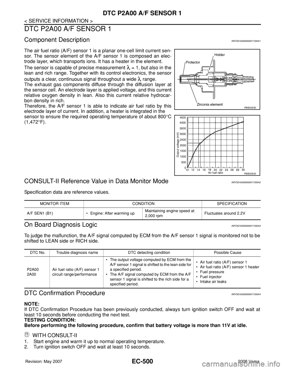
The air fuel ratio (A/F) sensor 1 is a planar one-cell limit current sen-
sor. The sensor element of the A/F sensor 1 is composed an elec-
trode layer, which transports ions. It has a heater in the element.
The sensor is capable of precise measurement = 1, but also in the
lean and rich range. Together with its control electronics, the sensor
outputs a clear, continuous signal throughout a wide range.
The exhaust gas components diffuse through the diffusion layer at
the sensor cell. An electrode layer is applied voltage, and this current
relative oxygen density in lean. Also this current relative hydrocar-
bon density in rich.
Therefore, the A/F sensor 1 is able to indicate air fuel ratio by this
electrode layer of current. In addition, a heater is integrated in the
sensor to ensure the required operating temperature of about 800°C
(1,472°F).
CONSULT-II Reference Value in Data Monitor ModeINFOID:0000000001703042
Specification data are reference values.
On Board Diagnosis LogicINFOID:0000000001703043
To judge the malfunction, the A/F signal computed by ECM from the A/F sensor 1 signal is monitored not to be
shifted to LEAN side or RICH side.
DTC Confirmation ProcedureINFOID:0000000001703044
NOTE:
If DTC Confirmation Procedure has been previously conducted, always turn ignition switch OFF and wait at
least 10 seconds before conducting the next test.
TESTING CONDITION:
Before performing the following procedure, confirm that battery voltage is more than 11V at idle.
WITH CONSULT-II
1. Start engine and warm it up to normal operating temperature.
2. Turn ignition switch OFF and wait at least 10 seconds.
PBIB3353E
PBIB3354E
MONITOR ITEM CONDITION SPECIFICATION
A/F SEN1 (B1) • Engine: After warming upMaintaining engine speed at
2,000 rpmFluctuates around 2.2V
DTC No. Trouble diagnosis name DTC detecting condition Possible Cause
P2A00
2A00Air fuel ratio (A/F) sensor 1
circuit range/performance• The output voltage computed by ECM from the
A/F sensor 1 signal is shifted to the lean side for
a specified period.
• The A/F signal computed by ECM from the A/F
sensor 1 signal is shifted to the rich side for a
specified period.• Air fuel ratio (A/F) sensor 1
• Air fuel ratio (A/F) sensor 1 heater
• Fuel pressure
• Fuel injector
• Intake air leaks
Page 1600 of 2771
EC-526
< SERVICE INFORMATION >
FUEL PUMP
FUEL PUMP
DescriptionINFOID:0000000001703065
SYSTEM DESCRIPTION
*: ECM determines the start signal status by the signals of engine speed and battery voltage.
The ECM activates the fuel pump for several seconds after the ignition switch is turned ON to improve engine
startability. If the ECM receives a engine speed signal from the crankshaft position sensor (POS) and cam-
shaft position sensor (PHASE), it knows that the engine is rotating, and causes the pump to operate. If the
engine speed signal is not received when the ignition switch is ON, the engine stalls. The ECM stops pump
operation and prevents battery discharging, thereby improving safety. The ECM does not directly drive the fuel
pump. It controls the ON/OFF fuel pump relay, which in turn controls the fuel pump.
COMPONENT DESCRIPTION
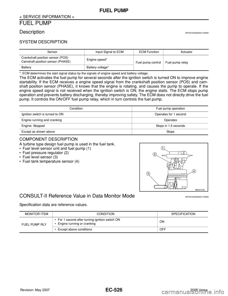
A turbine type design fuel pump is used in the fuel tank.
• Fuel level sensor unit and fuel pump (1)
• Fuel pressure regulator (2)
• Fuel level sensor (3)
• Fuel tank temperature sensor (4)
CONSULT-II Reference Value in Data Monitor ModeINFOID:0000000001703066
Specification data are reference values.
Sensor Input Signal to ECM ECM Function Actuator
Crankshaft position sensor (POS)
Camshaft position sensor (PHASE)Engine speed*
Fuel pump control Fuel pump relay
Battery Battery voltage*
Condition Fuel pump operation
Ignition switch is turned to ON Operates for 1 second
Engine running and crankingOperates
Engine: StoppedStops in 1.5 seconds
Except as shown aboveSt ops
BBIA0704E
MONITOR ITEM CONDITION SPECIFICATION
FUEL PUMP RLY• For 1 second after turning ignition switch ON
• Engine running or crankingON
• Except above conditions OFF
Page 1602 of 2771
EC-528
< SERVICE INFORMATION >
FUEL PUMP
Diagnosis Procedure
INFOID:0000000001703068
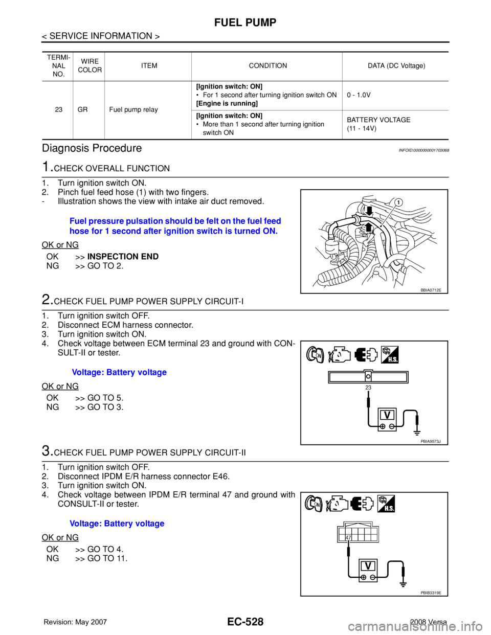
1.CHECK OVERALL FUNCTION
1. Turn ignition switch ON.
2. Pinch fuel feed hose (1) with two fingers.
- Illustration shows the view with intake air duct removed.
OK or NG
OK >>INSPECTION END
NG >> GO TO 2.
2.CHECK FUEL PUMP POWER SUPPLY CIRCUIT-I
1. Turn ignition switch OFF.
2. Disconnect ECM harness connector.
3. Turn ignition switch ON.
4. Check voltage between ECM terminal 23 and ground with CON-
SULT-II or tester.
OK or NG
OK >> GO TO 5.
NG >> GO TO 3.
3.CHECK FUEL PUMP POWER SUPPLY CIRCUIT-II
1. Turn ignition switch OFF.
2. Disconnect IPDM E/R harness connector E46.
3. Turn ignition switch ON.
4. Check voltage between IPDM E/R terminal 47 and ground with
CONSULT-II or tester.
OK or NG
OK >> GO TO 4.
NG >> GO TO 11.
TERMI-
NAL
NO.WIRE
COLORITEM CONDITION DATA (DC Voltage)
23 GR Fuel pump relay[Ignition switch: ON]
• For 1 second after turning ignition switch ON
[Engine is running]0 - 1.0V
[Ignition switch: ON]
• More than 1 second after turning ignition
switch ONBATTERY VOLTAGE
(11 - 14V)
Fuel pressure pulsation should be felt on the fuel feed
hose for 1 second after ignition switch is turned ON.
BBIA0712E
Voltage: Battery voltage
PBIA9573J
Voltage: Battery voltage
PBIB3319E
Page 1613 of 2771
IGNITION SIGNAL
EC-539
< SERVICE INFORMATION >
C
D
E
F
G
H
I
J
K
L
MA
EC
N
P O
1. Turn ignition switch OFF.
2. Disconnect ignition coil harness connector.
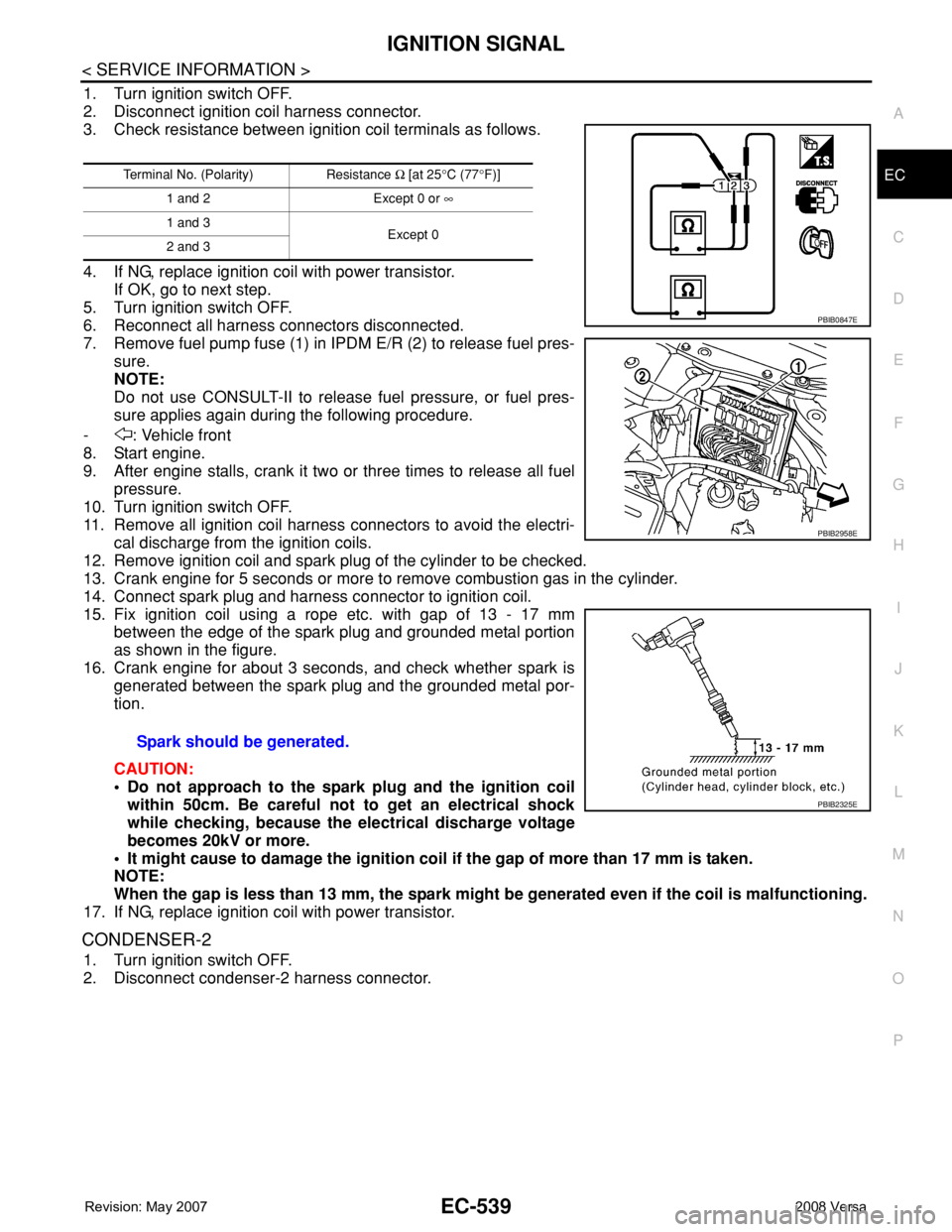
3. Check resistance between ignition coil terminals as follows.
4. If NG, replace ignition coil with power transistor.
If OK, go to next step.
5. Turn ignition switch OFF.
6. Reconnect all harness connectors disconnected.
7. Remove fuel pump fuse (1) in IPDM E/R (2) to release fuel pres-
sure.
NOTE:
Do not use CONSULT-II to release fuel pressure, or fuel pres-
sure applies again during the following procedure.
- : Vehicle front
8. Start engine.
9. After engine stalls, crank it two or three times to release all fuel
pressure.
10. Turn ignition switch OFF.
11. Remove all ignition coil harness connectors to avoid the electri-
cal discharge from the ignition coils.
12. Remove ignition coil and spark plug of the cylinder to be checked.
13. Crank engine for 5 seconds or more to remove combustion gas in the cylinder.
14. Connect spark plug and harness connector to ignition coil.
15. Fix ignition coil using a rope etc. with gap of 13 - 17 mm
between the edge of the spark plug and grounded metal portion
as shown in the figure.
16. Crank engine for about 3 seconds, and check whether spark is
generated between the spark plug and the grounded metal por-
tion.
CAUTION:
• Do not approach to the spark plug and the ignition coil
within 50cm. Be careful not to get an electrical shock
while checking, because the electrical discharge voltage
becomes 20kV or more.
• It might cause to damage the ignition coil if the gap of more than 17 mm is taken.
NOTE:
When the gap is less than 13 mm, the spark might be generated even if the coil is malfunctioning.
17. If NG, replace ignition coil with power transistor.
CONDENSER-2
1. Turn ignition switch OFF.
2. Disconnect condenser-2 harness connector.
Terminal No. (Polarity) Resistance Ω [at 25°C (77°F)]
1 and 2 Except 0 or ∞
1 and 3
Except 0
2 and 3
Spark should be generated.
PBIB0847E
PBIB2958E
PBIB2325E
Page 1622 of 2771

EC-548
< SERVICE INFORMATION >
SERVICE DATA AND SPECIFICATIONS (SDS)
SERVICE DATA AND SPECIFICATIONS (SDS)
Fuel PressureINFOID:0000000001703081
Idle Speed and Ignition TimingINFOID:0000000001703082
*: Under the following conditions:
• Air conditioner switch: OFF
• Electric load: OFF (Lights, heater fan & rear window defogger)
• Steering wheel: Kept in straight-ahead position
Calculated Load ValueINFOID:0000000001703083
Mass Air Flow SensorINFOID:0000000001703084
*: Engine is warmed up to normal operating temperature and running under no load.
Intake Air Temperature SensorINFOID:0000000001703085
Engine Coolant Temperature SensorINFOID:0000000001703086
Fuel pressure at idle
Approximately 350 kPa (3.57 kg/cm2, 51 psi)
Target idle speedA/T No load* (in P or N position)
700 ± 50 rpm CVT No load* (In P or N position)
M/T No load* (in Neutral position)
Air conditioner: ONA/T In P or N position
850 rpm or more CVT In P or N position
M/T In Neutral position
Ignition timingA/T In P or N position
13 ± 5° BTDC CVT In P or N position
M/T In Neutral position
Calculated load value% (Using CONSULT-II or GST)
At idle10 - 35
At 2,500 rpm10 - 35
Supply voltageBattery voltage (11 - 14V)
Output voltage at idle1.0 - 1.3*V
Mass air flow (Using CONSULT-II or GST)1.0 - 4.0 g·m/sec at idle*
2.0 - 10.0 g·m/sec at 2,500 rpm*
Temperature °C (°F) Resistance kΩ
25 (77)1.800 - 2.200
Temperature °C (°F) Resistance kΩ
20 (68)2.1 - 2.9
50 (122)0.68 - 1.00
90 (194)0.236 - 0.260
Page 1681 of 2771

EM-4
< SERVICE INFORMATION >
PRECAUTIONS
2. Use the Intelligent Key or mechanical key to turn the ignition switch to the ″ACC″ position. At this time, the
steering lock will be released.
3. Disconnect both battery cables. The steering lock will remain released and the steering wheel can be
rotated.
4. Perform the necessary repair operation.
5. When the repair work is completed, return the ignition switch to the ″LOCK″ position before connecting
the battery cables. (At this time, the steering lock mechanism will engage.)
6. Perform a self-diagnosis check of all control units using CONSULT-III.
Precaution for Drain CoolantINFOID:0000000001702463
• Drain coolant when engine is cooled.
Precaution for Disconnecting Fuel PipingINFOID:0000000001702464
• Before starting work, make sure no fire or spark producing items are in the work area.
• Release fuel pressure before disassembly.
• After disconnecting pipes, plug openings to stop fuel leakage.
Precaution for Removal and DisassemblyINFOID:0000000001702465
• When instructed to use special service tools, use the specified tools. Always be careful to work safely, avoid
forceful or uninstructed operations.
• Exercise maximum care to avoid damage to mating or sliding surfaces.
• Cover openings of engine system with tape or the equivalent, if necessary, to seal out foreign materials.
• Mark and arrange disassembly parts in an organized way for easy troubleshooting and assembly.
• When loosening nuts and bolts, as a basic rule, start with the one furthest outside, then the one diagonally
opposite, and so on. If the order of loosening is specified, do exactly as specified. Power tools may be used
where noted in the step.
Precaution for Inspection, Repair and ReplacementINFOID:0000000001702466
• Before repairing or replacing, thoroughly inspect parts. Inspect new replacement parts in the same way, and
replace if necessary.
Precaution for Assembly and InstallationINFOID:0000000001702467
• Use torque wrench to tighten bolts or nuts to specification.
• When tightening nuts and bolts, as a basic rule, equally tighten in several different steps starting with the
ones in center, then ones on inside and outside diagonally in this order. If the order of tightening is specified,
do exactly as specified.
• Replace with new gasket, packing, oil seal or O-ring.
• Thoroughly wash, clean, and air-blow each part. Carefully check oil or coolant passages for any restriction
and blockage.
• Avoid damaging sliding or mating surfaces. Completely remove foreign materials such as cloth lint or dust.
Before assembly, oil sliding surfaces well.
• Release air within route after draining coolant.
• Before starting engine, apply fuel pressure to fuel lines with turning ignition switch ON (with engine stopped).
Then make sure that there are no leaks at fuel line connections.
• After repairing, start engine and increase engine speed to check coolant, fuel, oil, and exhaust systems for
leakage.
Parts Requiring Angular TighteningINFOID:0000000001702468
• Use an angle wrench for the final tightening of the following engine parts:
- Cylinder head bolts
- Camshaft sprocket (INT)
- Main bearing cap bolts
- Connecting rod cap nuts
- Crankshaft pulley bolt (No angle wrench is required as the bolt flange is provided with notches for angular
tightening)
Page 1710 of 2771
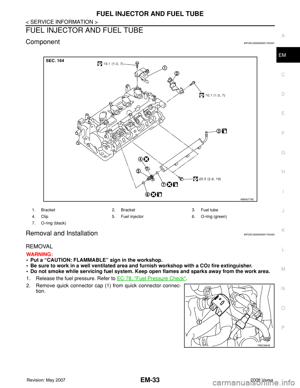
FUEL INJECTOR AND FUEL TUBE
EM-33
< SERVICE INFORMATION >
C
D
E
F
G
H
I
J
K
L
MA
EM
N
P O
FUEL INJECTOR AND FUEL TUBE
ComponentINFOID:0000000001702491
Removal and InstallationINFOID:0000000001702492
REMOVAL
WARNING:
• Put a “CAUTION: FLAMMABLE” sign in the workshop.
• Be sure to work in a well ventilated area and furnish workshop with a CO
2 fire extinguisher.
• Do not smoke while servicing fuel system. Keep open flames and sparks away from the work area.
1. Release the fuel pressure. Refer to EC-78, "
Fuel Pressure Check".
2. Remove quick connector cap (1) from quick connector connec-
tion.
1. Bracket 2. Bracket 3. Fuel tube
4. Clip 5. Fuel injector 6. O-ring (green)
7. O-ring (black)
WBIA0779E
PBIC3664E
Page 1724 of 2771
CAMSHAFT
EM-47
< SERVICE INFORMATION >
C
D
E
F
G
H
I
J
K
L
MA
EM
N
P O
CAMSHAFT
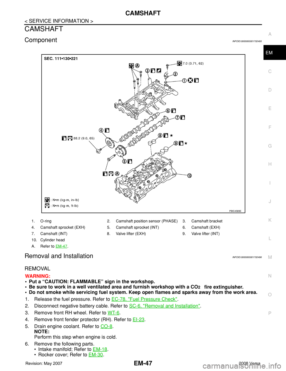
ComponentINFOID:0000000001702495
Removal and InstallationINFOID:0000000001702496
REMOVAL
WARNING:
• Put a “CAUTION: FLAMMABLE” sign in the workshop.
• Be sure to work in a well ventilated area and furnish workshop with a CO
2 fire extinguisher.
• Do not smoke while servicing fuel system. Keep open flames and sparks away from the work area.
1. Release the fuel pressure. Refer to EC-78, "
Fuel Pressure Check".
2. Disconnect negative battery cable. Refer to SC-6, "
Removal and Installation".
3. Remove front RH wheel. Refer to WT-6
.
4. Remove front fender protector (RH). Refer to EI-23
.
5. Drain engine coolant. Refer to CO-8
.
NOTE:
Perform this step when engine is cold.
6. Remove the following parts.
• Intake manifold; Refer to EM-18
.
• Rocker cover; Refer to EM-30
.
1. O-ring 2. Camshaft position sensor (PHASE) 3. Camshaft bracket
4. Camshaft sprocket (EXH) 5. Camshaft sprocket (INT) 6. Camshaft (EXH)
7. Camshaft (INT) 8. Valve lifter (EXH) 9. Valve lifter (INT)
10. Cylinder head
A. Refer to EM-47
.
PBIC4589E