2008 NISSAN TIIDA Engine oil
[x] Cancel search: Engine oilPage 1222 of 2771
EC-148
< SERVICE INFORMATION >
DTC P0011 IVT CONTROL
On Board Diagnosis Logic
INFOID:0000000001702619
FAIL-SAFE MODE
ECM enters in fail-safe mode when the malfunction is detected.
DTC Confirmation ProcedureINFOID:0000000001702620
CAUTION:
Always drive at a safe speed.
NOTE:
•If DTC P0011 is displayed with DTC P0075, first perform trouble diagnosis for DTC P0075.
See EC-162
.
• If DTC Confirmation Procedure has been previously conducted, always turn ignition switch OFF and wait at
least 10 seconds before conducting the next test.
TESTING CONDITION:
Before performing the following procedure, confirm that battery voltage is between 10V and 16V at
idle.
WITH CONSULT-II
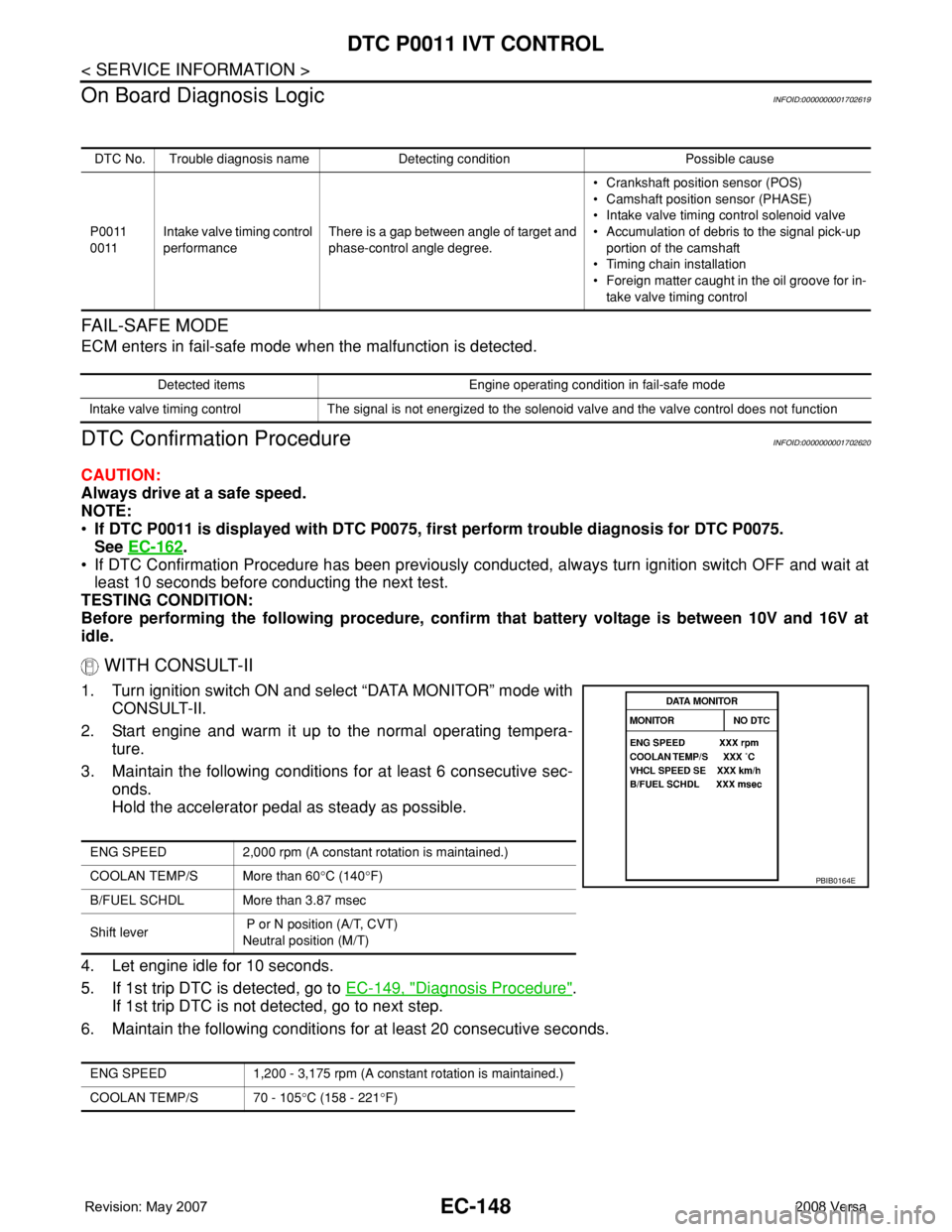
1. Turn ignition switch ON and select “DATA MONITOR” mode with
CONSULT-II.
2. Start engine and warm it up to the normal operating tempera-
ture.
3. Maintain the following conditions for at least 6 consecutive sec-
onds.
Hold the accelerator pedal as steady as possible.
4. Let engine idle for 10 seconds.
5. If 1st trip DTC is detected, go to EC-149, "
Diagnosis Procedure".
If 1st trip DTC is not detected, go to next step.
6. Maintain the following conditions for at least 20 consecutive seconds.
DTC No. Trouble diagnosis name Detecting condition Possible cause
P0011
0011Intake valve timing control
performanceThere is a gap between angle of target and
phase-control angle degree.• Crankshaft position sensor (POS)
• Camshaft position sensor (PHASE)
• Intake valve timing control solenoid valve
• Accumulation of debris to the signal pick-up
portion of the camshaft
• Timing chain installation
• Foreign matter caught in the oil groove for in-
take valve timing control
Detected items Engine operating condition in fail-safe mode
Intake valve timing control The signal is not energized to the solenoid valve and the valve control does not function
ENG SPEED 2,000 rpm (A constant rotation is maintained.)
COOLAN TEMP/S More than 60°C (140°F)
B/FUEL SCHDL More than 3.87 msec
Shift lever P or N position (A/T, CVT)
Neutral position (M/T)
ENG SPEED 1,200 - 3,175 rpm (A constant rotation is maintained.)
COOLAN TEMP/S 70 - 105°C (158 - 221°F)
PBIB0164E
Page 1223 of 2771
DTC P0011 IVT CONTROL
EC-149
< SERVICE INFORMATION >
C
D
E
F
G
H
I
J
K
L
MA
EC
N
P O7. If 1st trip DTC is detected, go to EC-149, "Diagnosis Procedure".
WITH GST
Follow the procedure “WITH CONSULT-II” above.
Diagnosis ProcedureINFOID:0000000001702621
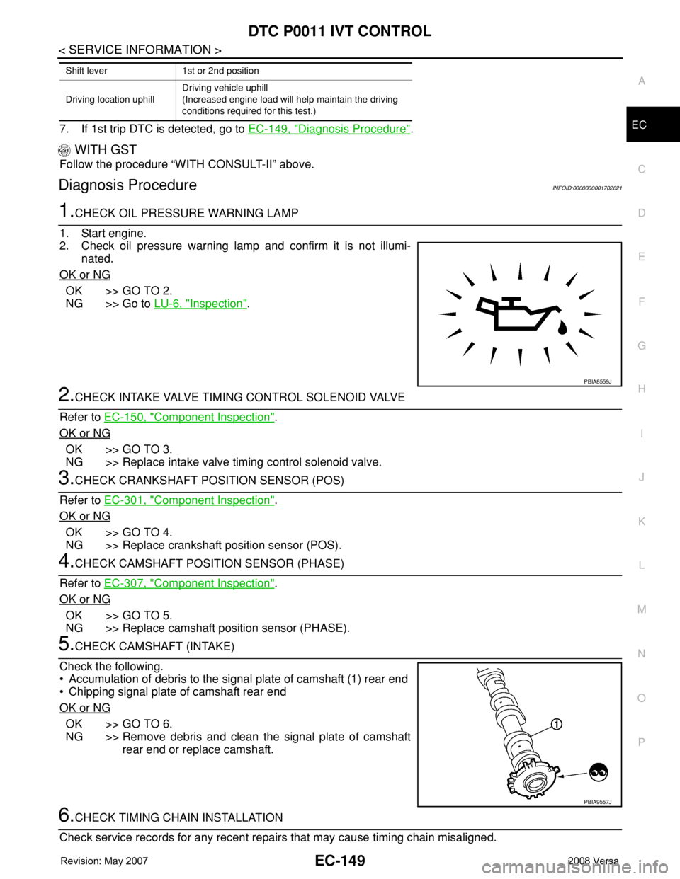
1.CHECK OIL PRESSURE WARNING LAMP
1. Start engine.
2. Check oil pressure warning lamp and confirm it is not illumi-
nated.
OK or NG
OK >> GO TO 2.
NG >> Go to LU-6, "
Inspection".
2.CHECK INTAKE VALVE TIMING CONTROL SOLENOID VALVE
Refer to EC-150, "
Component Inspection".
OK or NG
OK >> GO TO 3.
NG >> Replace intake valve timing control solenoid valve.
3.CHECK CRANKSHAFT POSITION SENSOR (POS)
Refer to EC-301, "
Component Inspection".
OK or NG
OK >> GO TO 4.
NG >> Replace crankshaft position sensor (POS).
4.CHECK CAMSHAFT POSITION SENSOR (PHASE)
Refer to EC-307, "
Component Inspection".
OK or NG
OK >> GO TO 5.
NG >> Replace camshaft position sensor (PHASE).
5.CHECK CAMSHAFT (INTAKE)
Check the following.
• Accumulation of debris to the signal plate of camshaft (1) rear end
• Chipping signal plate of camshaft rear end
OK or NG
OK >> GO TO 6.
NG >> Remove debris and clean the signal plate of camshaft
rear end or replace camshaft.
6.CHECK TIMING CHAIN INSTALLATION
Check service records for any recent repairs that may cause timing chain misaligned.
Shift lever 1st or 2nd position
Driving location uphillDriving vehicle uphill
(Increased engine load will help maintain the driving
conditions required for this test.)
PBIA8559J
PBIA9557J
Page 1236 of 2771
EC-162
< SERVICE INFORMATION >
DTC P0075 IVT CONTROL SOLENOID VALVE
DTC P0075 IVT CONTROL SOLENOID VALVE
Component DescriptionINFOID:0000000001702640
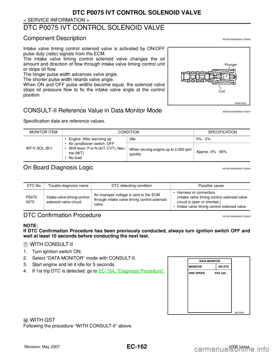
Intake valve timing control solenoid valve is activated by ON/OFF
pulse duty (ratio) signals from the ECM.
The intake valve timing control solenoid valve changes the oil
amount and direction of flow through intake valve timing control unit
or stops oil flow.
The longer pulse width advances valve angle.
The shorter pulse width retards valve angle.
When ON and OFF pulse widths become equal, the solenoid valve
stops oil pressure flow to fix the intake valve angle at the control
position.
CONSULT-II Reference Value in Data Monitor ModeINFOID:0000000001702641
Specification data are reference values.
On Board Diagnosis LogicINFOID:0000000001702642
DTC Confirmation ProcedureINFOID:0000000001702643
NOTE:
If DTC Confirmation Procedure has been previously conducted, always turn ignition switch OFF and
wait at least 10 seconds before conducting the next test.
WITH CONSULT-II
1. Turn ignition switch ON.
2. Select “DATA MONITOR” mode with CONSULT-II.
3. Start engine and let it idle for 5 seconds.
4. If 1st trip DTC is detected, go to EC-164, "
Diagnosis Procedure".
WITH GST
Following the procedure “WITH CONSULT-II” above.
PBIB1842E
MONITOR ITEM CONDITION SPECIFICATION
INT/V SOL (B1)• Engine: After warming up
• Air conditioner switch: OFF
• Shift lever: P or N (A/T, CVT), Neu-
tral (M/T)
•No loadIdle 0% - 2%
When revving engine up to 2,000 rpm
quicklyApprox. 0% - 90%
DTC No. Trouble diagnosis name DTC detecting condition Possible cause
P0075
0075Intake valve timing control
solenoid valve circuitAn improper voltage is sent to the ECM
through intake valve timing control solenoid
valve.• Harness or connectors
(Intake valve timing control solenoid valve
circuit is open or shorted.)
• Intake valve timing control solenoid valve
SEF058Y
Page 1336 of 2771
EC-262
< SERVICE INFORMATION >
DTC P0171 FUEL INJECTION SYSTEM FUNCTION
1. Install all removed parts.
2. Start engine and warm it up to normal operating temperature.
3. Check mass air flow sensor signal in Service $01 with GST.
OK or NG
OK >> GO TO 7.
NG >> Check connectors for rusted terminals or loose connections in the mass air flow sensor circuit or
ground. Refer to EC-167
.
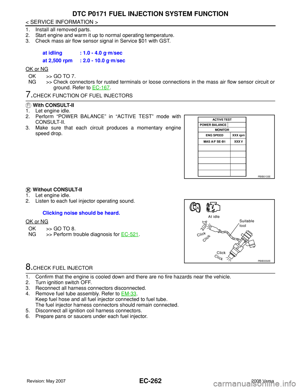
7.CHECK FUNCTION OF FUEL INJECTORS
With CONSULT-II
1. Let engine idle.
2. Perform “POWER BALANCE” in “ACTIVE TEST” mode with
CONSULT-II.
3. Make sure that each circuit produces a momentary engine
speed drop.
Without CONSULT-II
1. Let engine idle.
2. Listen to each fuel injector operating sound.
OK or NG
OK >> GO TO 8.
NG >> Perform trouble diagnosis for EC-521
.
8.CHECK FUEL INJECTOR
1. Confirm that the engine is cooled down and there are no fire hazards near the vehicle.
2. Turn ignition switch OFF.
3. Reconnect all harness connectors disconnected.
4. Remove fuel tube assembly. Refer to EM-33
.
Keep fuel hose and all fuel injector connected to fuel tube.
The fuel injector harness connectors should remain connected.
5. Disconnect all ignition coil harness connectors.
6. Prepare pans or saucers under each fuel injector.at idling : 1.0 - 4.0 g·m/sec
at 2,500 rpm : 2.0 - 10.0 g·m/sec
PBIB0133E
Clicking noise should be heard.
PBIB3332E
Page 1343 of 2771
DTC P0172 FUEL INJECTION SYSTEM FUNCTION
EC-269
< SERVICE INFORMATION >
C
D
E
F
G
H
I
J
K
L
MA
EC
N
P OOK or NG
OK >> GO TO 7.
NG >> Check connectors for rusted terminals or loose connections in the mass air flow sensor circuit or
ground. Refer to EC-167
.
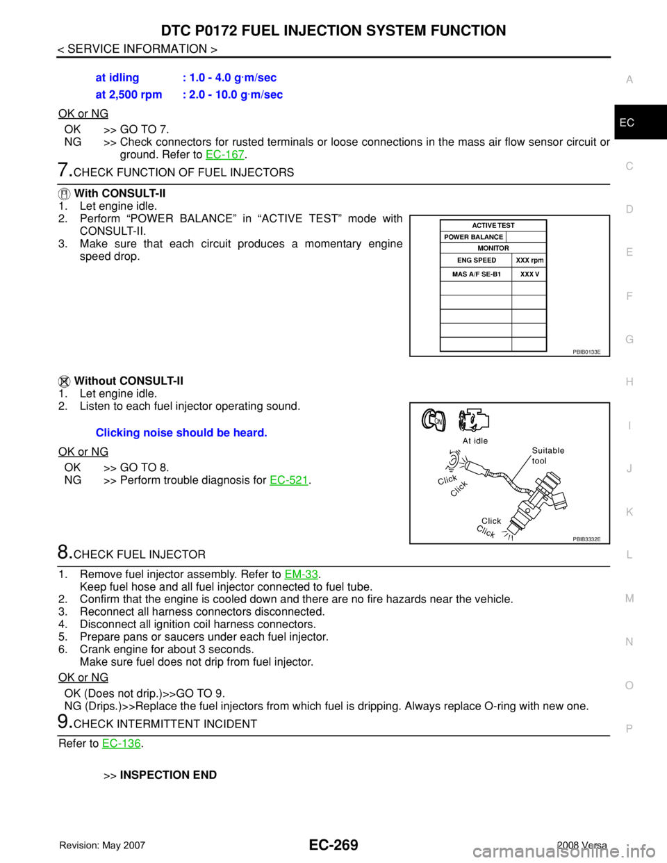
7.CHECK FUNCTION OF FUEL INJECTORS
With CONSULT-II
1. Let engine idle.
2. Perform “POWER BALANCE” in “ACTIVE TEST” mode with
CONSULT-II.
3. Make sure that each circuit produces a momentary engine
speed drop.
Without CONSULT-II
1. Let engine idle.
2. Listen to each fuel injector operating sound.
OK or NG
OK >> GO TO 8.
NG >> Perform trouble diagnosis for EC-521
.
8.CHECK FUEL INJECTOR
1. Remove fuel injector assembly. Refer to EM-33
.
Keep fuel hose and all fuel injector connected to fuel tube.
2. Confirm that the engine is cooled down and there are no fire hazards near the vehicle.
3. Reconnect all harness connectors disconnected.
4. Disconnect all ignition coil harness connectors.
5. Prepare pans or saucers under each fuel injector.
6. Crank engine for about 3 seconds.
Make sure fuel does not drip from fuel injector.
OK or NG
OK (Does not drip.)>>GO TO 9.
NG (Drips.)>>Replace the fuel injectors from which fuel is dripping. Always replace O-ring with new one.
9.CHECK INTERMITTENT INCIDENT
Refer to EC-136
.
>>INSPECTION END at idling : 1.0 - 4.0 g·m/sec
at 2,500 rpm : 2.0 - 10.0 g·m/sec
PBIB0133E
Clicking noise should be heard.
PBIB3332E
Page 1360 of 2771
EC-286
< SERVICE INFORMATION >
DTC P0300 - P0304 MULTIPLE CYLINDER MISFIRE, NO. 1 - 4 CYLINDER MIS-
FIRE
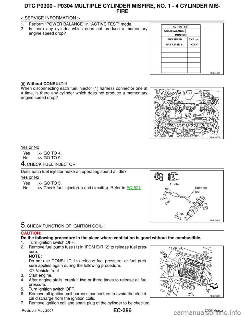
1. Perform “POWER BALANCE” in “ACTIVE TEST” mode.
2. Is there any cylinder which does not produce a momentary
engine speed drop?
Without CONSULT-II
When disconnecting each fuel injector (1) harness connector one at
a time, is there any cylinder which does not produce a momentary
engine speed drop?
Ye s o r N o
Ye s > > G O T O 4 .
No >> GO TO 9.
4.CHECK FUEL INJECTOR
Does each fuel injector make an operating sound at idle?
Ye s o r N o
Ye s > > G O T O 5 .
No >> Check fuel injector(s) and circuit(s). Refer to EC-521
.
5.CHECK FUNCTION OF IGNITION COIL-I
CAUTION:
Do the following procedure in the place where ventilation is good without the combustible.
1. Turn ignition switch OFF.
2. Remove fuel pump fuse (1) in IPDM E/R (2) to release fuel pres-
sure.
NOTE:
Do not use CONSULT-II to release fuel pressure, or fuel pres-
sure applies again during the following procedure.
- : Vehicle front
3. Start engine.
4. After engine stalls, crank it two or three times to release all fuel
pressure.
5. Turn ignition switch OFF.
6. Remove all ignition coil harness connectors to avoid the electri-
cal discharge from the ignition coils.
7. Remove ignition coil and spark plug of the cylinder to be checked.
PBIB0133E
PBIA9870J
PBIB3332E
PBIB2958E
Page 1361 of 2771
DTC P0300 - P0304 MULTIPLE CYLINDER MISFIRE, NO. 1 - 4 CYLINDER MIS-
FIRE
EC-287
< SERVICE INFORMATION >
C
D
E
F
G
H
I
J
K
L
MA
EC
N
P O
8. Crank engine for 5 seconds or more to remove combustion gas in the cylinder.
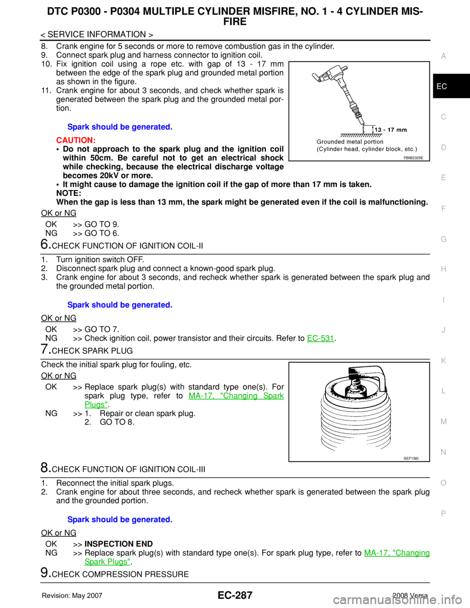
9. Connect spark plug and harness connector to ignition coil.
10. Fix ignition coil using a rope etc. with gap of 13 - 17 mm
between the edge of the spark plug and grounded metal portion
as shown in the figure.
11. Crank engine for about 3 seconds, and check whether spark is
generated between the spark plug and the grounded metal por-
tion.
CAUTION:
• Do not approach to the spark plug and the ignition coil
within 50cm. Be careful not to get an electrical shock
while checking, because the electrical discharge voltage
becomes 20kV or more.
• It might cause to damage the ignition coil if the gap of more than 17 mm is taken.
NOTE:
When the gap is less than 13 mm, the spark might be generated even if the coil is malfunctioning.
OK or NG
OK >> GO TO 9.
NG >> GO TO 6.
6.CHECK FUNCTION OF IGNITION COIL-II
1. Turn ignition switch OFF.
2. Disconnect spark plug and connect a known-good spark plug.
3. Crank engine for about 3 seconds, and recheck whether spark is generated between the spark plug and
the grounded metal portion.
OK or NG
OK >> GO TO 7.
NG >> Check ignition coil, power transistor and their circuits. Refer to EC-531
.
7.CHECK SPARK PLUG
Check the initial spark plug for fouling, etc.
OK or NG
OK >> Replace spark plug(s) with standard type one(s). For
spark plug type, refer to MA-17, "
Changing Spark
Plugs".
NG >> 1. Repair or clean spark plug.
2. GO TO 8.
8.CHECK FUNCTION OF IGNITION COIL-III
1. Reconnect the initial spark plugs.
2. Crank engine for about three seconds, and recheck whether spark is generated between the spark plug
and the grounded portion.
OK or NG
OK >>INSPECTION END
NG >> Replace spark plug(s) with standard type one(s). For spark plug type, refer to MA-17, "
Changing
Spark Plugs".
9.CHECK COMPRESSION PRESSURESpark should be generated.
PBIB2325E
Spark should be generated.
SEF156I
Spark should be generated.
Page 1385 of 2771
DTC P0420 THREE WAY CATALYST FUNCTION
EC-311
< SERVICE INFORMATION >
C
D
E
F
G
H
I
J
K
L
MA
EC
N
P O
OK >> GO TO 6.
NG >> Perform EC-523, "
Diagnosis Procedure".
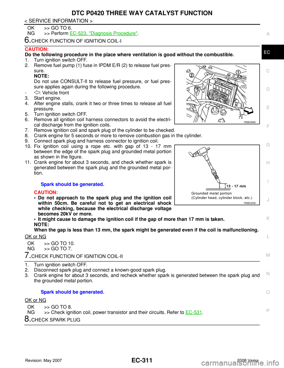
6.CHECK FUNCTION OF IGNITION COIL-I
CAUTION:
Do the following procedure in the place where ventilation is good without the combustible.
1. Turn ignition switch OFF.
2. Remove fuel pump (1) fuse in IPDM E/R (2) to release fuel pres-
sure.
NOTE:
Do not use CONSULT-II to release fuel pressure, or fuel pres-
sure applies again during the following procedure.
- : Vehicle front
3. Start engine.
4. After engine stalls, crank it two or three times to release all fuel
pressure.
5. Turn ignition switch OFF.
6. Remove all ignition coil harness connectors to avoid the electri-
cal discharge from the ignition coils.
7. Remove ignition coil and spark plug of the cylinder to be checked.
8. Crank engine for 5 seconds or more to remove combustion gas in the cylinder.
9. Connect spark plug and harness connector to ignition coil.
10. Fix ignition coil using a rope etc. with gap of 13 - 17 mm
between the edge of the spark plug and grounded metal portion
as shown in the figure.
11. Crank engine for about 3 seconds, and check whether spark is
generated between the spark plug and the grounded metal por-
tion.
CAUTION:
• Do not approach to the spark plug and the ignition coil
within 50cm. Be careful not to get an electrical shock
while checking, because the electrical discharge voltage
becomes 20kV or more.
• It might cause to damage the ignition coil if the gap of more than 17 mm is taken.
NOTE:
When the gap is less than 13 mm, the spark might be generated even if the coil is malfunctioning.
OK or NG
OK >> GO TO 10.
NG >> GO TO 7.
7.CHECK FUNCTION OF IGNITION COIL-II
1. Turn ignition switch OFF.
2. Disconnect spark plug and connect a known-good spark plug.
3. Crank engine for about 3 seconds, and recheck whether spark is generated between the spark plug and
the grounded metal portion.
OK or NG
OK >> GO TO 8.
NG >> Check ignition coil, power transistor and their circuits. Refer to EC-531
.
8.CHECK SPARK PLUGSpark should be generated.
PBIB2958E
PBIB2325E
Spark should be generated.