2008 NISSAN TIIDA Engine oil
[x] Cancel search: Engine oilPage 1386 of 2771
EC-312
< SERVICE INFORMATION >
DTC P0420 THREE WAY CATALYST FUNCTION
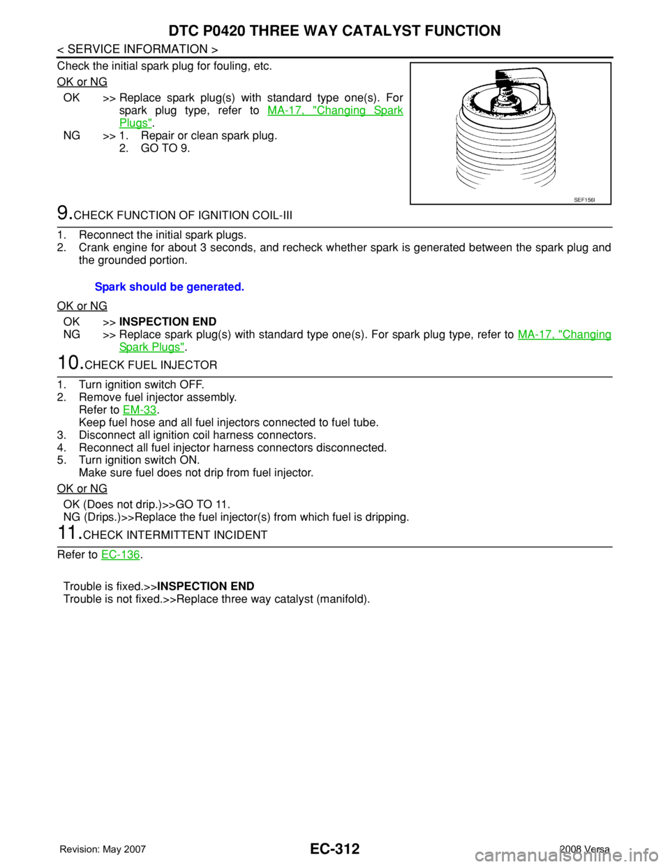
Check the initial spark plug for fouling, etc.
OK or NG
OK >> Replace spark plug(s) with standard type one(s). For
spark plug type, refer to MA-17, "
Changing Spark
Plugs".
NG >> 1. Repair or clean spark plug.
2. GO TO 9.
9.CHECK FUNCTION OF IGNITION COIL-III
1. Reconnect the initial spark plugs.
2. Crank engine for about 3 seconds, and recheck whether spark is generated between the spark plug and
the grounded portion.
OK or NG
OK >>INSPECTION END
NG >> Replace spark plug(s) with standard type one(s). For spark plug type, refer to MA-17, "
Changing
Spark Plugs".
10.CHECK FUEL INJECTOR
1. Turn ignition switch OFF.
2. Remove fuel injector assembly.
Refer to EM-33
.
Keep fuel hose and all fuel injectors connected to fuel tube.
3. Disconnect all ignition coil harness connectors.
4. Reconnect all fuel injector harness connectors disconnected.
5. Turn ignition switch ON.
Make sure fuel does not drip from fuel injector.
OK or NG
OK (Does not drip.)>>GO TO 11.
NG (Drips.)>>Replace the fuel injector(s) from which fuel is dripping.
11 .CHECK INTERMITTENT INCIDENT
Refer to EC-136
.
Trouble is fixed.>>INSPECTION END
Trouble is not fixed.>>Replace three way catalyst (manifold).
SEF156I
Spark should be generated.
Page 1487 of 2771
DTC P1217 ENGINE OVER TEMPERATURE
EC-413
< SERVICE INFORMATION >
C
D
E
F
G
H
I
J
K
L
MA
EC
N
P O Cooling Fan Relay Operation
The ECM controls cooling fan relays in the IPDM E/R through CAN communication line.
CONSULT-II Reference Value in Data Monitor ModeINFOID:0000000001702930
Specification data are reference values.
On Board Diagnosis LogicINFOID:0000000001702931
If the cooling fan or another component in the cooling system malfunctions, engine coolant temperature will
rise. When the engine coolant temperature reaches an abnormally high temperature condition, a malfunction
is indicated.
This self-diagnosis has the one trip detection logic.
CAUTION:
When a malfunction is indicated, be sure to replace the coolant. Refer to CO-8, "
Changing Engine
Coolant". Also, replace the engine oil. Refer to LU-7, "Changing Engine Oil".
1. Fill radiator with coolant up to specified level with a filling speed of 2 liters per minute. Be sure to
use coolant with the proper mixture ratio. Refer to MA-11, "
Anti-freeze Coolant Mixture Ratio".
2. After refilling coolant, run engine to ensure that no water-flow noise is emitted.
Overall Function CheckINFOID:0000000001702932
Use this procedure to check the overall function of the cooling fan. During this check, a DTC might not be con-
firmed.
WARNING:
Cooling fan speedCooling fan relay
123
Stop (OFF) OFF OFF OFF
Low (LOW) ON OFF OFF
High (HI) OFF ON ON
MONITOR ITEM CONDITION SPECIFICATION
AIR COND SIG• Engine: After warming up, idle
the engineAir conditioner switch: OFF OFF
Air conditioner switch: ON
(Compressor operates.)ON
COOLING FAN• Engine: After warming up, idle
the engine
• Air conditioner switch: OFFEngine coolant temperature: 97°C
(207°F) or lessOFF
Engine coolant temperature: Between
98°C (208°F) and 99°C (210°F) or
moreLOW
Engine coolant temperature: 100°C
(212°F) or moreHIGH
DTC No. Trouble diagnosis name DTC detecting condition Possible cause
P1217
1217Engine over temperature
(Overheat)• Cooling fan does not operate properly (Over-
heat).
• Cooling fan system does not operate properly
(Overheat).
• Engine coolant was not added to the system
using the proper filling method.
• Engine coolant is not within the specified
range.• Harness or connectors
(Cooling fan circuit is open or shorted.)
• Cooling fan
• IPDM E/R (Cooling fan relays)
•Radiator hose
•Radiator
• Reservoir tank
•Radiator cap
• Water pump
•Thermostat
• Water control valve
For more information, refer to EC-424,
"Main 13 Causes of Overheating".
Page 1595 of 2771
FUEL INJECTOR
EC-521
< SERVICE INFORMATION >
C
D
E
F
G
H
I
J
K
L
MA
EC
N
P O
FUEL INJECTOR
Component DescriptionINFOID:0000000001703059
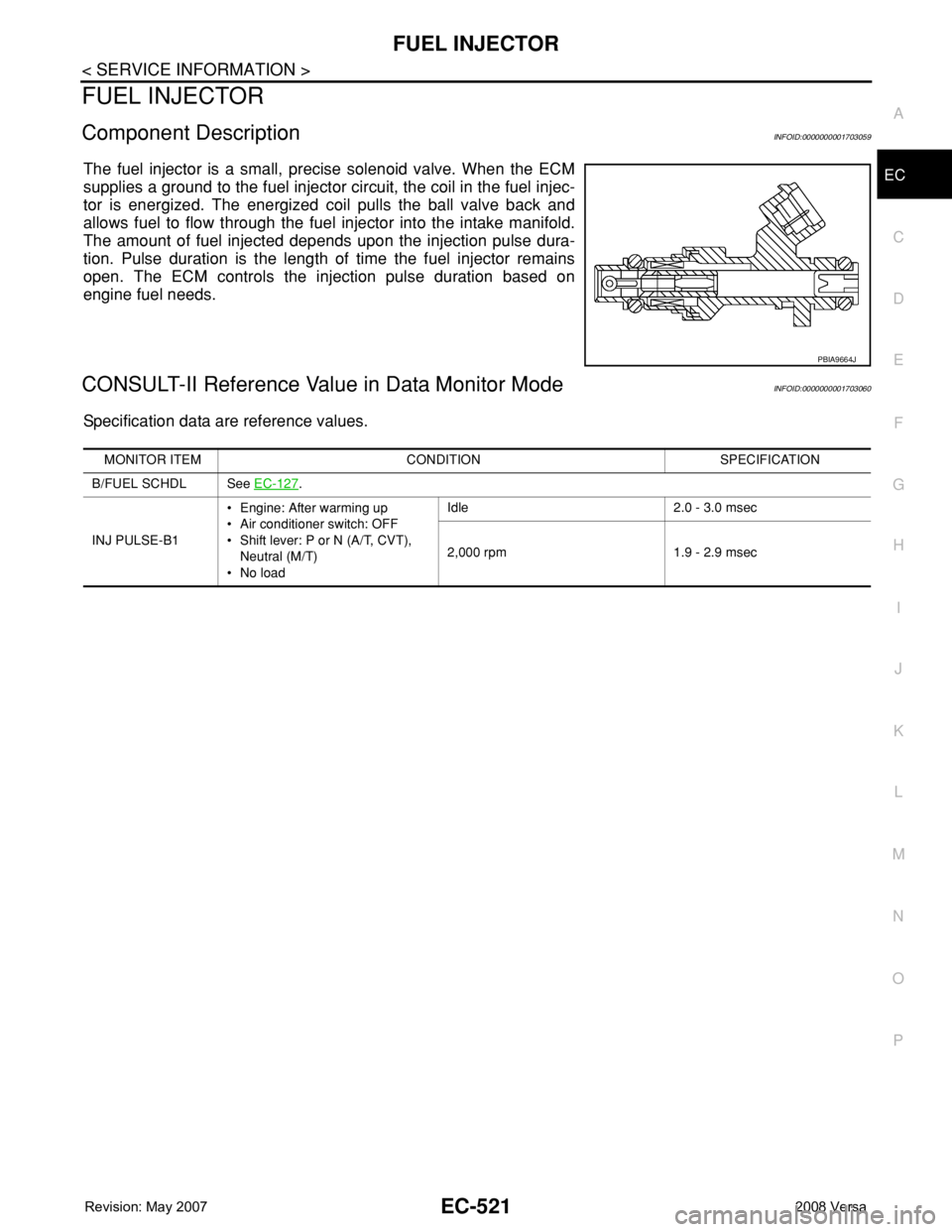
The fuel injector is a small, precise solenoid valve. When the ECM
supplies a ground to the fuel injector circuit, the coil in the fuel injec-
tor is energized. The energized coil pulls the ball valve back and
allows fuel to flow through the fuel injector into the intake manifold.
The amount of fuel injected depends upon the injection pulse dura-
tion. Pulse duration is the length of time the fuel injector remains
open. The ECM controls the injection pulse duration based on
engine fuel needs.
CONSULT-II Reference Value in Data Monitor ModeINFOID:0000000001703060
Specification data are reference values.
PBIA9664J
MONITOR ITEM CONDITION SPECIFICATION
B/FUEL SCHDL See EC-127
.
INJ PULSE-B1• Engine: After warming up
• Air conditioner switch: OFF
• Shift lever: P or N (A/T, CVT),
Neutral (M/T)
•No loadIdle 2.0 - 3.0 msec
2,000 rpm 1.9 - 2.9 msec
Page 1613 of 2771
IGNITION SIGNAL
EC-539
< SERVICE INFORMATION >
C
D
E
F
G
H
I
J
K
L
MA
EC
N
P O
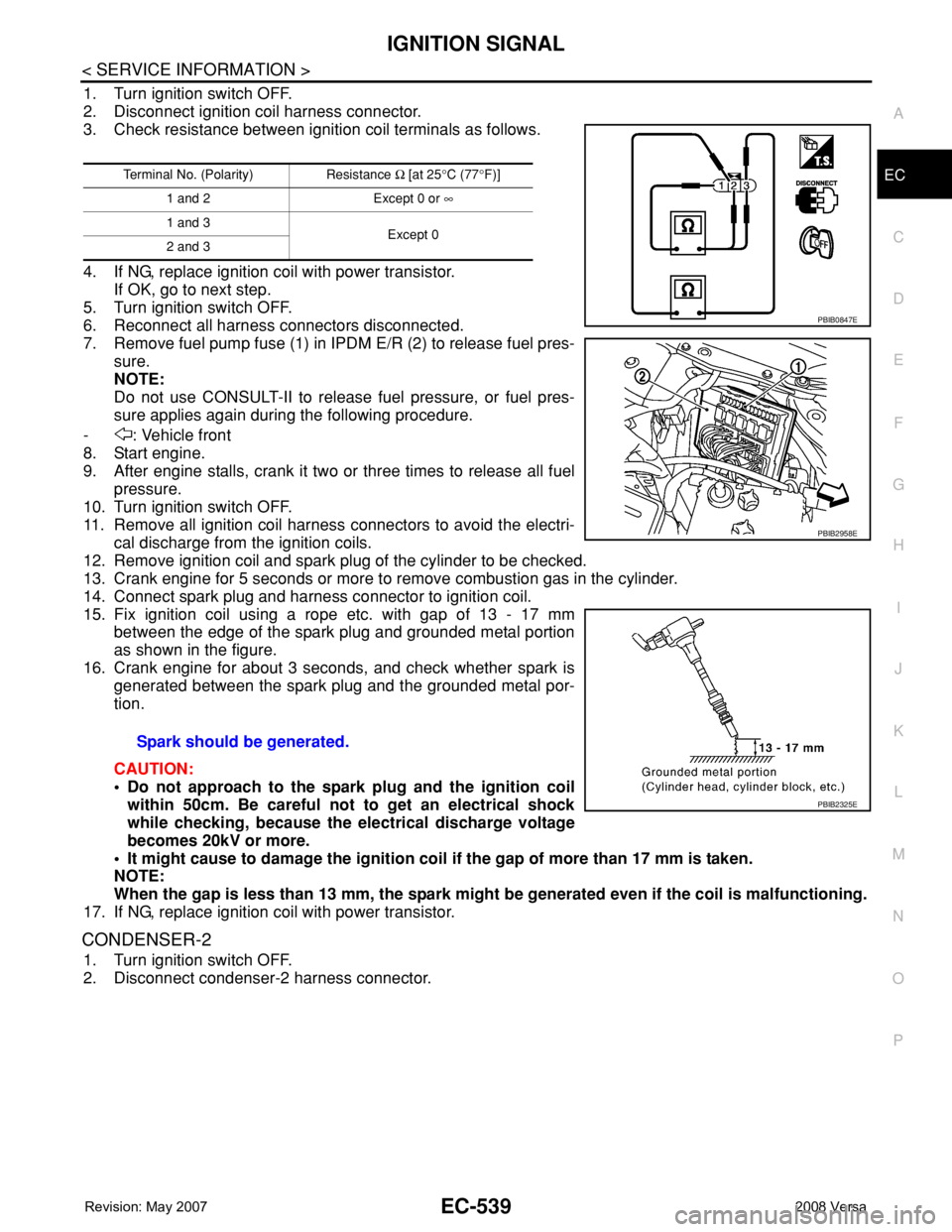
1. Turn ignition switch OFF.
2. Disconnect ignition coil harness connector.
3. Check resistance between ignition coil terminals as follows.
4. If NG, replace ignition coil with power transistor.
If OK, go to next step.
5. Turn ignition switch OFF.
6. Reconnect all harness connectors disconnected.
7. Remove fuel pump fuse (1) in IPDM E/R (2) to release fuel pres-
sure.
NOTE:
Do not use CONSULT-II to release fuel pressure, or fuel pres-
sure applies again during the following procedure.
- : Vehicle front
8. Start engine.
9. After engine stalls, crank it two or three times to release all fuel
pressure.
10. Turn ignition switch OFF.
11. Remove all ignition coil harness connectors to avoid the electri-
cal discharge from the ignition coils.
12. Remove ignition coil and spark plug of the cylinder to be checked.
13. Crank engine for 5 seconds or more to remove combustion gas in the cylinder.
14. Connect spark plug and harness connector to ignition coil.
15. Fix ignition coil using a rope etc. with gap of 13 - 17 mm
between the edge of the spark plug and grounded metal portion
as shown in the figure.
16. Crank engine for about 3 seconds, and check whether spark is
generated between the spark plug and the grounded metal por-
tion.
CAUTION:
• Do not approach to the spark plug and the ignition coil
within 50cm. Be careful not to get an electrical shock
while checking, because the electrical discharge voltage
becomes 20kV or more.
• It might cause to damage the ignition coil if the gap of more than 17 mm is taken.
NOTE:
When the gap is less than 13 mm, the spark might be generated even if the coil is malfunctioning.
17. If NG, replace ignition coil with power transistor.
CONDENSER-2
1. Turn ignition switch OFF.
2. Disconnect condenser-2 harness connector.
Terminal No. (Polarity) Resistance Ω [at 25°C (77°F)]
1 and 2 Except 0 or ∞
1 and 3
Except 0
2 and 3
Spark should be generated.
PBIB0847E
PBIB2958E
PBIB2325E
Page 1638 of 2771
FRONT BUMPER
EI-15
< ON-VEHICLE REPAIR >
C
D
E
F
G
H
J
K
L
MA
B
EI
N
O
P
CAUTION:
Bumper fascia is made of resin. Do not apply strong force to it, and be careful to prevent contact with
oil.
REMOVAL
1. Open hood.
2. Remove front grille. Refer to EI-20
.
3. Remove front fender protectors RH/LH. Refer to EI-23
.
4. Remove front valance and engine undercover.
5. Remove screws of front bumper fascia RH/LH.
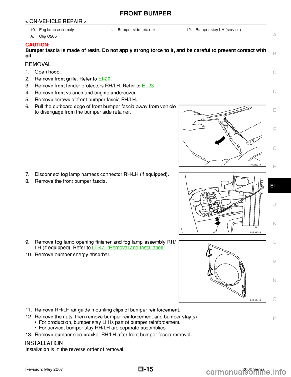
6. Pull the outboard edge of front bumper fascia away from vehicle
to disengage from the bumper side retainer.
7. Disconnect fog lamp harness connector RH/LH (if equipped).
8. Remove the front bumper fascia.
9. Remove fog lamp opening finisher and fog lamp assembly RH/
LH (if equipped). Refer to LT-47, "
Removal and Installation".
10. Remove bumper energy absorber.
11. Remove RH/LH air guide mounting clips of bumper reinforcement.
12. Remove the nuts, then remove bumper reinforcement and bumper stay(s):
• For production, bumper stay LH is part of bumper reinforcement.
• For service, bumper stay RH/LH are separate assemblies.
13. Remove bumper side bracket RH/LH after front bumper fascia removal.
INSTALLATION
Installation is in the reverse order of removal.
10. Fog lamp assembly 11. Bumper side retainer 12. Bumper stay LH (service)
A. Clip C205
PIIB2537J
PIIB2538J
PIIB2543J
Page 1678 of 2771
EM-1
ENGINE
C
D
E
F
G
H
I
J
K
L
M
SECTION EM
A
EM
N
O
P
CONTENTS
ENGINE MECHANICAL
SERVICE INFORMATION ............................3
PRECAUTIONS ...................................................3
Precaution for Supplemental Restraint System
(SRS) "AIR BAG" and "SEAT BELT PRE-TEN-
SIONER" ...................................................................
3
Precaution for Procedure without Cowl Top Cover ......3
Precaution Necessary for Steering Wheel Rota-
tion After Battery Disconnect .....................................
3
Precaution for Drain Coolant .....................................4
Precaution for Disconnecting Fuel Piping .................4
Precaution for Removal and Disassembly ................4
Precaution for Inspection, Repair and Replace-
ment ..........................................................................
4
Precaution for Assembly and Installation ..................4
Parts Requiring Angular Tightening ..........................4
Precaution for Liquid Gasket .....................................5
PREPARATION ...................................................7
Special Service Tool .................................................7
Commercial Service Tool ..........................................9
NOISE, VIBRATION AND HARSHNESS
(NVH) TROUBLESHOOTING ............................
11
NVH Troubleshooting - Engine Noise .....................11
Use the Chart Below to Help You Find the Cause
of the Symptom .......................................................
12
DRIVE BELTS ....................................................13
Component ..............................................................13
Checking Drive Belts ...............................................13
Tension Adjustment ................................................13
Removal and Installation .........................................13
Component ..............................................................14
Removal and Installation of Drive Belt Auto Ten-
sioner ......................................................................
14
AIR CLEANER AND AIR DUCT ........................16
Component ..............................................................16
Removal and Installation .........................................16
Changing Air Cleaner Filter .....................................17
INTAKE MANIFOLD .........................................18
Component ..............................................................18
Removal and Installation .........................................18
EXHAUST MANIFOLD ......................................21
Component ..............................................................21
Removal and Installation .........................................21
OIL PAN ............................................................24
Component ..............................................................24
Removal and Installation .........................................24
IGNITION COIL, SPARK PLUG AND ROCK-
ER COVER ........................................................
30
Component ..............................................................30
Removal and Installation .........................................30
FUEL INJECTOR AND FUEL TUBE ................33
Component ..............................................................33
Removal and Installation .........................................33
TIMING CHAIN ..................................................37
Component ..............................................................37
Removal and Installation .........................................38
CAMSHAFT .......................................................47
Component ..............................................................47
Removal and Installation .........................................47
Valve Clearance ......................................................55
OIL SEAL ..........................................................59
Removal and Installation of Valve Oil Seal ..............59
Removal and Installation of Front Oil Seal ..............59
Removal and Installation of Rear Oil Seal ...............60
CYLINDER HEAD .............................................62
On-Vehicle Service ..................................................62
Component ..............................................................63
Removal and Installation .........................................63
Component ..............................................................65
Disassembly and Assembly .....................................66
Inspection After Disassembly ..................................67
Page 1681 of 2771

EM-4
< SERVICE INFORMATION >
PRECAUTIONS
2. Use the Intelligent Key or mechanical key to turn the ignition switch to the ″ACC″ position. At this time, the
steering lock will be released.
3. Disconnect both battery cables. The steering lock will remain released and the steering wheel can be
rotated.
4. Perform the necessary repair operation.
5. When the repair work is completed, return the ignition switch to the ″LOCK″ position before connecting
the battery cables. (At this time, the steering lock mechanism will engage.)
6. Perform a self-diagnosis check of all control units using CONSULT-III.
Precaution for Drain CoolantINFOID:0000000001702463
• Drain coolant when engine is cooled.
Precaution for Disconnecting Fuel PipingINFOID:0000000001702464
• Before starting work, make sure no fire or spark producing items are in the work area.
• Release fuel pressure before disassembly.
• After disconnecting pipes, plug openings to stop fuel leakage.
Precaution for Removal and DisassemblyINFOID:0000000001702465
• When instructed to use special service tools, use the specified tools. Always be careful to work safely, avoid
forceful or uninstructed operations.
• Exercise maximum care to avoid damage to mating or sliding surfaces.
• Cover openings of engine system with tape or the equivalent, if necessary, to seal out foreign materials.
• Mark and arrange disassembly parts in an organized way for easy troubleshooting and assembly.
• When loosening nuts and bolts, as a basic rule, start with the one furthest outside, then the one diagonally
opposite, and so on. If the order of loosening is specified, do exactly as specified. Power tools may be used
where noted in the step.
Precaution for Inspection, Repair and ReplacementINFOID:0000000001702466
• Before repairing or replacing, thoroughly inspect parts. Inspect new replacement parts in the same way, and
replace if necessary.
Precaution for Assembly and InstallationINFOID:0000000001702467
• Use torque wrench to tighten bolts or nuts to specification.
• When tightening nuts and bolts, as a basic rule, equally tighten in several different steps starting with the
ones in center, then ones on inside and outside diagonally in this order. If the order of tightening is specified,
do exactly as specified.
• Replace with new gasket, packing, oil seal or O-ring.
• Thoroughly wash, clean, and air-blow each part. Carefully check oil or coolant passages for any restriction
and blockage.
• Avoid damaging sliding or mating surfaces. Completely remove foreign materials such as cloth lint or dust.
Before assembly, oil sliding surfaces well.
• Release air within route after draining coolant.
• Before starting engine, apply fuel pressure to fuel lines with turning ignition switch ON (with engine stopped).
Then make sure that there are no leaks at fuel line connections.
• After repairing, start engine and increase engine speed to check coolant, fuel, oil, and exhaust systems for
leakage.
Parts Requiring Angular TighteningINFOID:0000000001702468
• Use an angle wrench for the final tightening of the following engine parts:
- Cylinder head bolts
- Camshaft sprocket (INT)
- Main bearing cap bolts
- Connecting rod cap nuts
- Crankshaft pulley bolt (No angle wrench is required as the bolt flange is provided with notches for angular
tightening)
Page 1682 of 2771
PRECAUTIONS
EM-5
< SERVICE INFORMATION >
C
D
E
F
G
H
I
J
K
L
MA
EM
N
P O
• Do not use a torque value for final tightening.
• The torque value for these parts are for a preliminary step.
• Ensure thread and seat surfaces are clean and coated with engine oil.
Precaution for Liquid GasketINFOID:0000000001702469
REMOVAL OF LIQUID GASKET SEALING
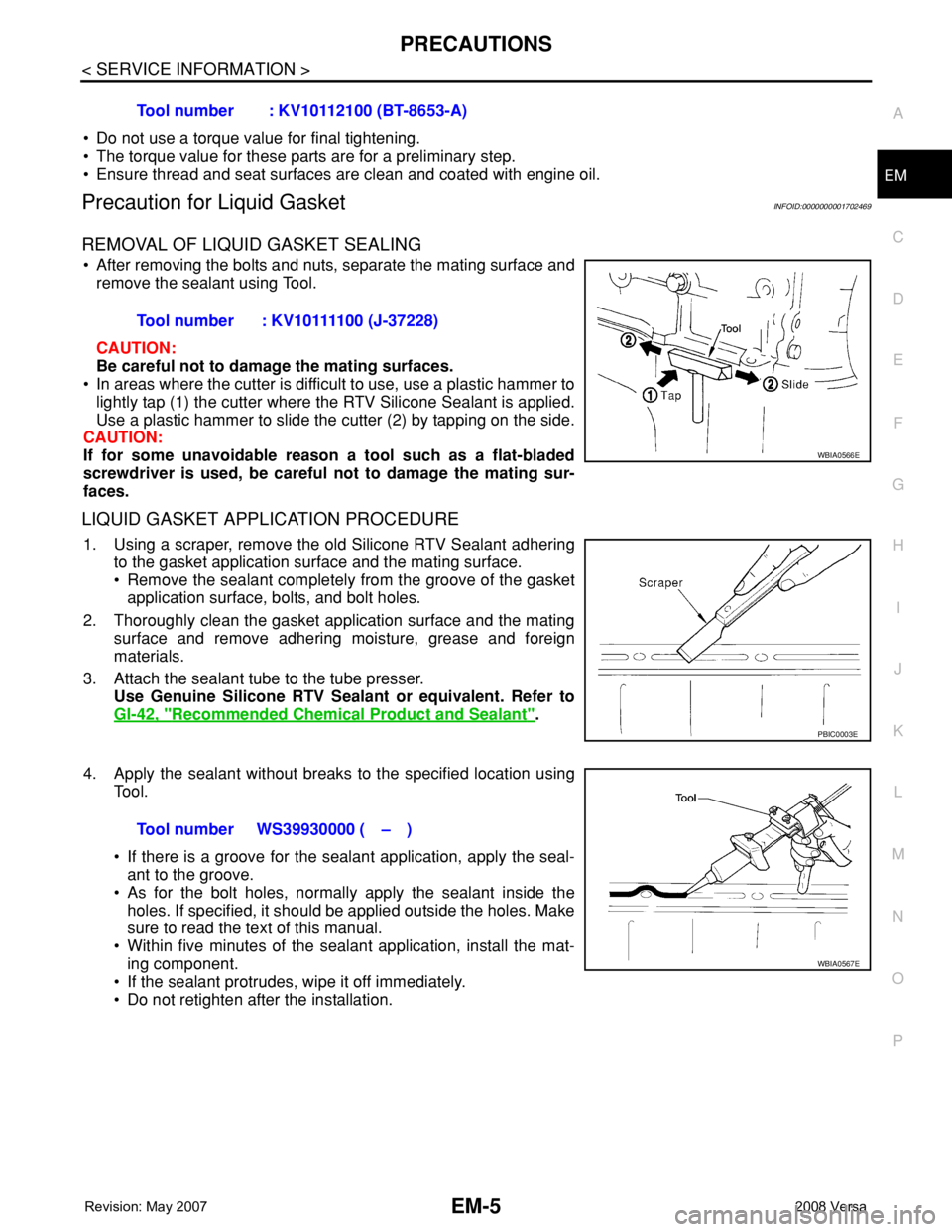
• After removing the bolts and nuts, separate the mating surface and
remove the sealant using Tool.
CAUTION:
Be careful not to damage the mating surfaces.
• In areas where the cutter is difficult to use, use a plastic hammer to
lightly tap (1) the cutter where the RTV Silicone Sealant is applied.
Use a plastic hammer to slide the cutter (2) by tapping on the side.
CAUTION:
If for some unavoidable reason a tool such as a flat-bladed
screwdriver is used, be careful not to damage the mating sur-
faces.
LIQUID GASKET APPLICATION PROCEDURE
1. Using a scraper, remove the old Silicone RTV Sealant adhering
to the gasket application surface and the mating surface.
• Remove the sealant completely from the groove of the gasket
application surface, bolts, and bolt holes.
2. Thoroughly clean the gasket application surface and the mating
surface and remove adhering moisture, grease and foreign
materials.
3. Attach the sealant tube to the tube presser.
Use Genuine Silicone RTV Sealant or equivalent. Refer to
GI-42, "
Recommended Chemical Product and Sealant".
4. Apply the sealant without breaks to the specified location using
Tool.
• If there is a groove for the sealant application, apply the seal-
ant to the groove.
• As for the bolt holes, normally apply the sealant inside the
holes. If specified, it should be applied outside the holes. Make
sure to read the text of this manual.
• Within five minutes of the sealant application, install the mat-
ing component.
• If the sealant protrudes, wipe it off immediately.
• Do not retighten after the installation.Tool number : KV10112100 (BT-8653-A)
Tool number : KV10111100 (J-37228)
WBIA0566E
PBIC0003E
Tool number WS39930000 ( – )
WBIA0567E