Page 1948 of 2771
REAR DOOR GLASS AND REGULATOR
GW-47
< SERVICE INFORMATION >
C
D
E
F
G
H
J
K
L
MA
B
GW
N
O
P
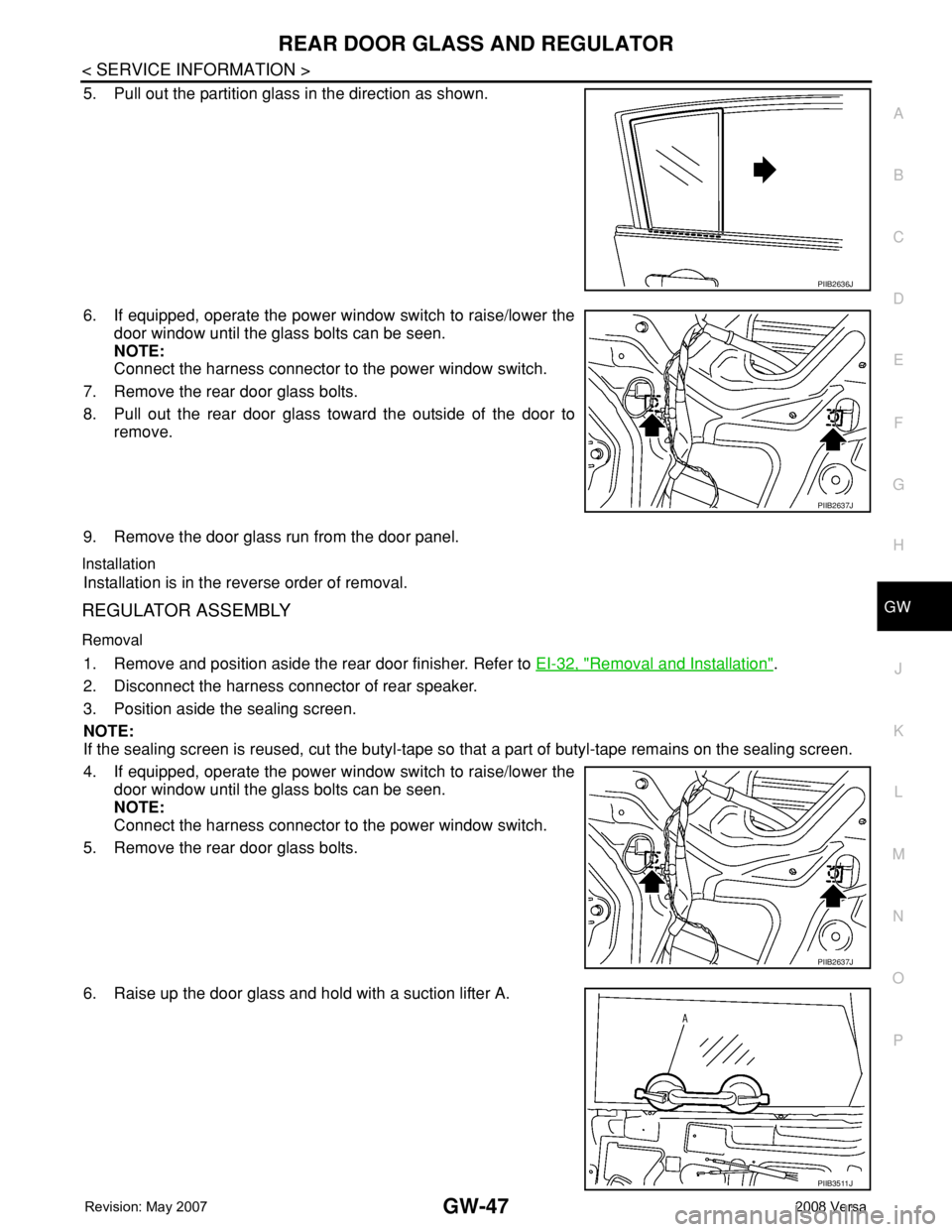
5. Pull out the partition glass in the direction as shown.
6. If equipped, operate the power window switch to raise/lower the
door window until the glass bolts can be seen.
NOTE:
Connect the harness connector to the power window switch.
7. Remove the rear door glass bolts.
8. Pull out the rear door glass toward the outside of the door to
remove.
9. Remove the door glass run from the door panel.
Installation
Installation is in the reverse order of removal.
REGULATOR ASSEMBLY
Removal
1. Remove and position aside the rear door finisher. Refer to EI-32, "Removal and Installation".
2. Disconnect the harness connector of rear speaker.
3. Position aside the sealing screen.
NOTE:
If the sealing screen is reused, cut the butyl-tape so that a part of butyl-tape remains on the sealing screen.
4. If equipped, operate the power window switch to raise/lower the
door window until the glass bolts can be seen.
NOTE:
Connect the harness connector to the power window switch.
5. Remove the rear door glass bolts.
6. Raise up the door glass and hold with a suction lifter A.
PIIB2636J
PIIB2637J
PIIB2637J
PIIB3511J
Page 1950 of 2771
REAR WINDOW DEFOGGER
GW-49
< SERVICE INFORMATION >
C
D
E
F
G
H
J
K
L
MA
B
GW
N
O
P
REAR WINDOW DEFOGGER
Component Parts and Harness Connector LocationINFOID:0000000001704166
System DescriptionINFOID:0000000001704167
The rear window defogger system is controlled by BCM (body control module) and IPDM E/R (intelligent
power distribution module engine room).
The rear window defogger only operates for approximately 15 minutes.
1. BCM M18, M20 (view with glove box
removed)2. Front air control M33 3. A. Rear window defogger ground
connector D413 (Hatchback)
B. Rear window defogger connector
D412 (Hatchback)
C. Condenser-1 D409, D411 (Hatch-
back)
4. A. Rear window defogger connector
B140 (Sedan)
B. Rear window defogger ground
connector B141 (Sedan)
C. Condenser-1 B130, B131 (Se-
dan)5. IPDM E/R E46, E48 6. Door mirror LH D4, RH D107 (with
heated mirrors)
7. Heated mirror relay M48 (with heat-
ed mirrors)
LIIA2929E
Page 1955 of 2771
GW-54
< SERVICE INFORMATION >
REAR WINDOW DEFOGGER
BCM Power Supply and Ground Circuit Inspection
INFOID:0000000001704175
Refer to BCS-15, "BCM Power Supply and Ground Circuit Inspection" .
Rear Window Defogger Switch Circuit InspectionINFOID:0000000001704176
1.CHECK REAR WINDOW DEFOGGER SWITCH OPERATION
With CONSULT-III
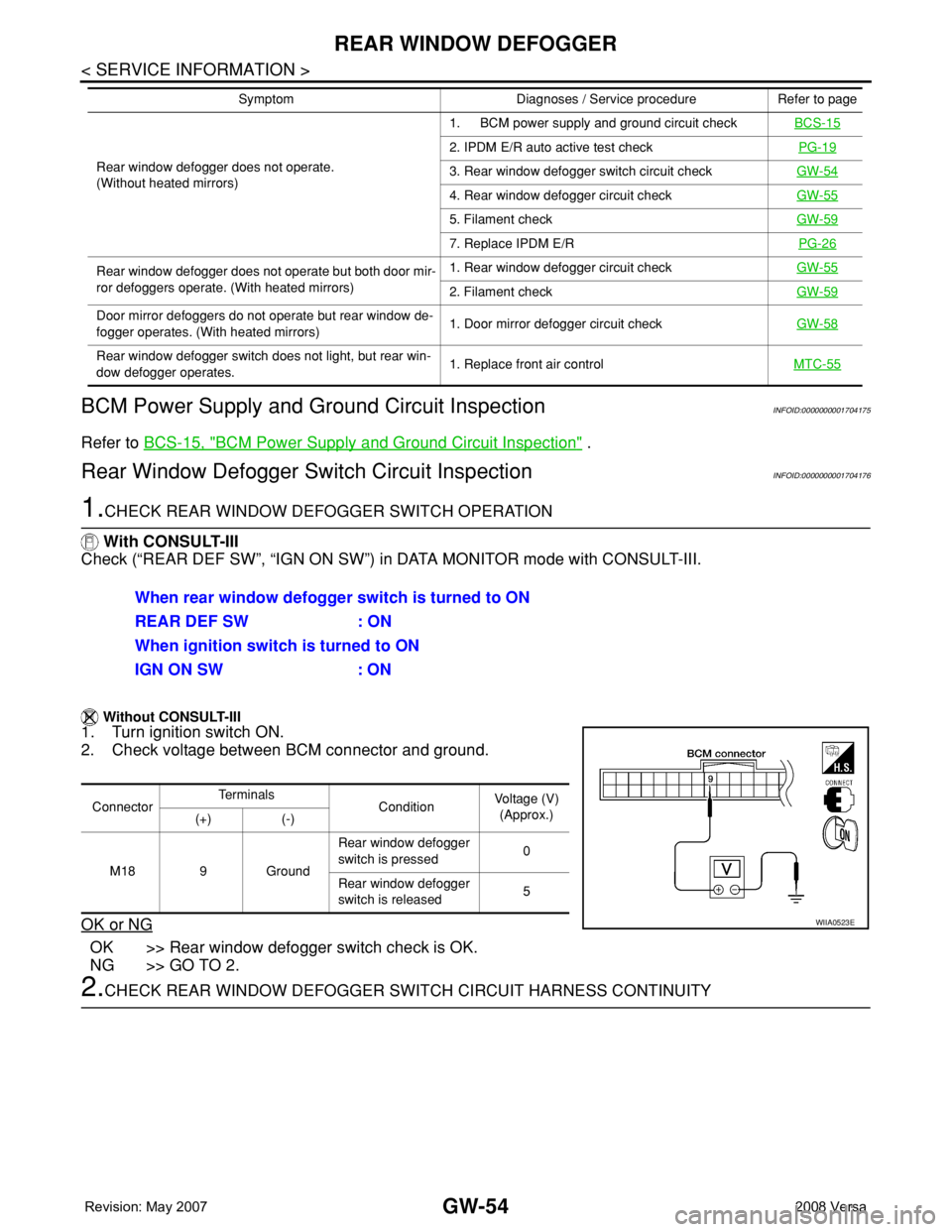
Check (“REAR DEF SW”, “IGN ON SW”) in DATA MONITOR mode with CONSULT-III.
Without CONSULT-III
1. Turn ignition switch ON.
2. Check voltage between BCM connector and ground.
OK or NG
OK >> Rear window defogger switch check is OK.
NG >> GO TO 2.
2.CHECK REAR WINDOW DEFOGGER SWITCH CIRCUIT HARNESS CONTINUITY
Rear window defogger does not operate.
(Without heated mirrors)1. BCM power supply and ground circuit checkBCS-15
2. IPDM E/R auto active test checkPG-19
3. Rear window defogger switch circuit checkGW-54
4. Rear window defogger circuit checkGW-55
5. Filament checkGW-59
7. Replace IPDM E/RPG-26
Rear window defogger does not operate but both door mir-
ror defoggers operate. (With heated mirrors)1. Rear window defogger circuit checkGW-55
2. Filament checkGW-59
Door mirror defoggers do not operate but rear window de-
fogger operates. (With heated mirrors)1. Door mirror defogger circuit checkGW-58
Rear window defogger switch does not light, but rear win-
dow defogger operates.1. Replace front air controlMTC-55
Symptom Diagnoses / Service procedure Refer to page
When rear window defogger switch is turned to ON
REAR DEF SW : ON
When ignition switch is turned to ON
IGN ON SW : ON
ConnectorTe r m i n a l s
ConditionVoltage (V)
(Approx.)
(+) (-)
M18 9 GroundRear window defogger
switch is pressed0
Rear window defogger
switch is released5
WIIA0523E
Page 1956 of 2771
REAR WINDOW DEFOGGER
GW-55
< SERVICE INFORMATION >
C
D
E
F
G
H
J
K
L
MA
B
GW
N
O
P
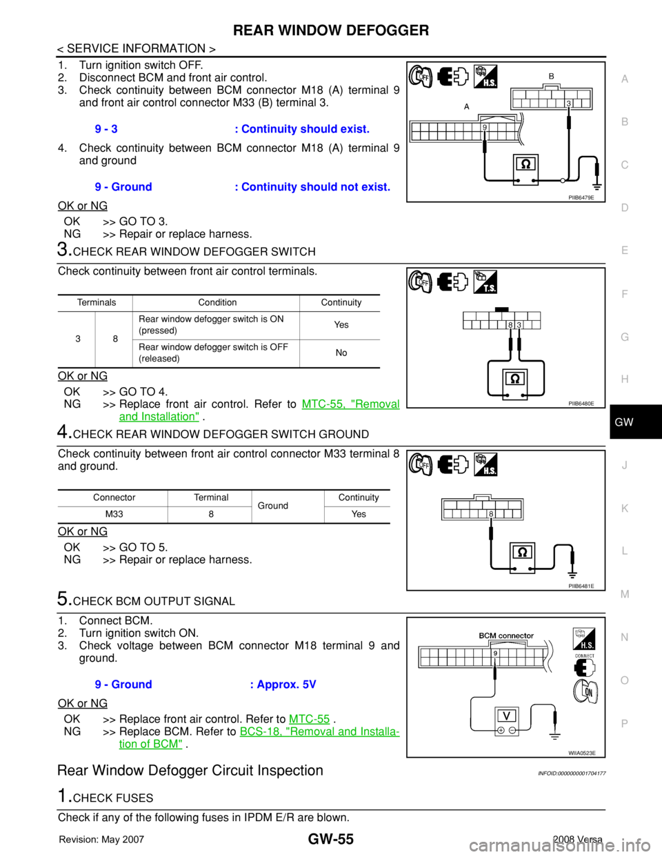
1. Turn ignition switch OFF.
2. Disconnect BCM and front air control.
3. Check continuity between BCM connector M18 (A) terminal 9
and front air control connector M33 (B) terminal 3.
4. Check continuity between BCM connector M18 (A) terminal 9
and ground
OK or NG
OK >> GO TO 3.
NG >> Repair or replace harness.
3.CHECK REAR WINDOW DEFOGGER SWITCH
Check continuity between front air control terminals.
OK or NG
OK >> GO TO 4.
NG >> Replace front air control. Refer to MTC-55, "
Removal
and Installation" .
4.CHECK REAR WINDOW DEFOGGER SWITCH GROUND
Check continuity between front air control connector M33 terminal 8
and ground.
OK or NG
OK >> GO TO 5.
NG >> Repair or replace harness.
5.CHECK BCM OUTPUT SIGNAL
1. Connect BCM.
2. Turn ignition switch ON.
3. Check voltage between BCM connector M18 terminal 9 and
ground.
OK or NG
OK >> Replace front air control. Refer to MTC-55 .
NG >> Replace BCM. Refer to BCS-18, "
Removal and Installa-
tion of BCM" .
Rear Window Defogger Circuit InspectionINFOID:0000000001704177
1.CHECK FUSES
Check if any of the following fuses in IPDM E/R are blown.9 - 3 : Continuity should exist.
9 - Ground : Continuity should not exist.
PIIB6479E
Terminals Condition Continuity
38Rear window defogger switch is ON
(pressed)Ye s
Rear window defogger switch is OFF
(released)No
PIIB6480E
Connector Terminal
GroundContinuity
8Yes M33
PIIB6481E
9 - Ground : Approx. 5V
WIIA0523E
Page 1957 of 2771
GW-56
< SERVICE INFORMATION >
REAR WINDOW DEFOGGER
OK or NG
OK >> GO TO 2.
NG >> If fuse is blown, be sure to eliminate cause of malfunction before installing new fuse.
2.CHECK REAR WINDOW DEFOGGER POWER SUPPLY CIRCUIT
1. Turn ignition switch OFF.
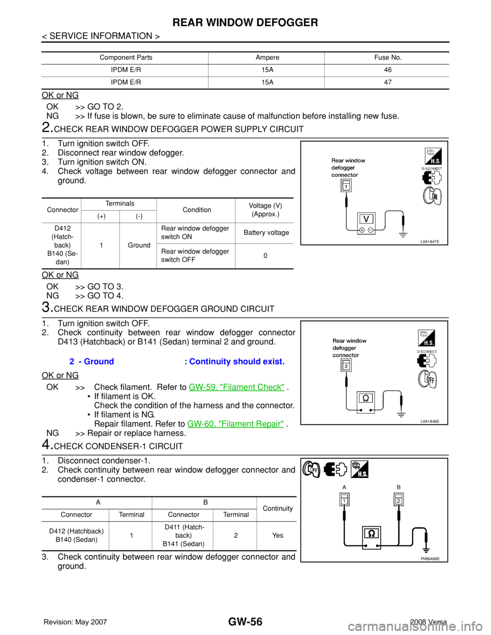
2. Disconnect rear window defogger.
3. Turn ignition switch ON.
4. Check voltage between rear window defogger connector and
ground.
OK or NG
OK >> GO TO 3.
NG >> GO TO 4.
3.CHECK REAR WINDOW DEFOGGER GROUND CIRCUIT
1. Turn ignition switch OFF.
2. Check continuity between rear window defogger connector
D413 (Hatchback) or B141 (Sedan) terminal 2 and ground.
OK or NG
OK >> Check filament. Refer to GW-59, "Filament Check" .
• If filament is OK.
Check the condition of the harness and the connector.
• If filament is NG.
Repair filament. Refer to GW-60, "
Filament Repair" .
NG >> Repair or replace harness.
4.CHECK CONDENSER-1 CIRCUIT
1. Disconnect condenser-1.
2. Check continuity between rear window defogger connector and
condenser-1 connector.
3. Check continuity between rear window defogger connector and
ground.
Component Parts Ampere Fuse No.
IPDM E/R 15A 46
IPDM E/R 15A 47
ConnectorTe r m i n a l s
ConditionVoltage (V)
(Approx.)
(+) (-)
D412
(Hatch-
back)
B140 (Se-
dan)1GroundRear window defogger
switch ON Battery voltage
Rear window defogger
switch OFF0
LIIA1847E
2 - Ground : Continuity should exist.
LIIA1848E
AB
Continuity
Connector Terminal Connector Terminal
D412 (Hatchback)
B140 (Sedan)1 D411 (Hatch-
back)
B141 (Sedan)2Yes
PIIB6486E
Page 1958 of 2771
REAR WINDOW DEFOGGER
GW-57
< SERVICE INFORMATION >
C
D
E
F
G
H
J
K
L
MA
B
GW
N
O
P
OK or NG
OK >> GO TO 5.
NG >> Repair or replace harness.
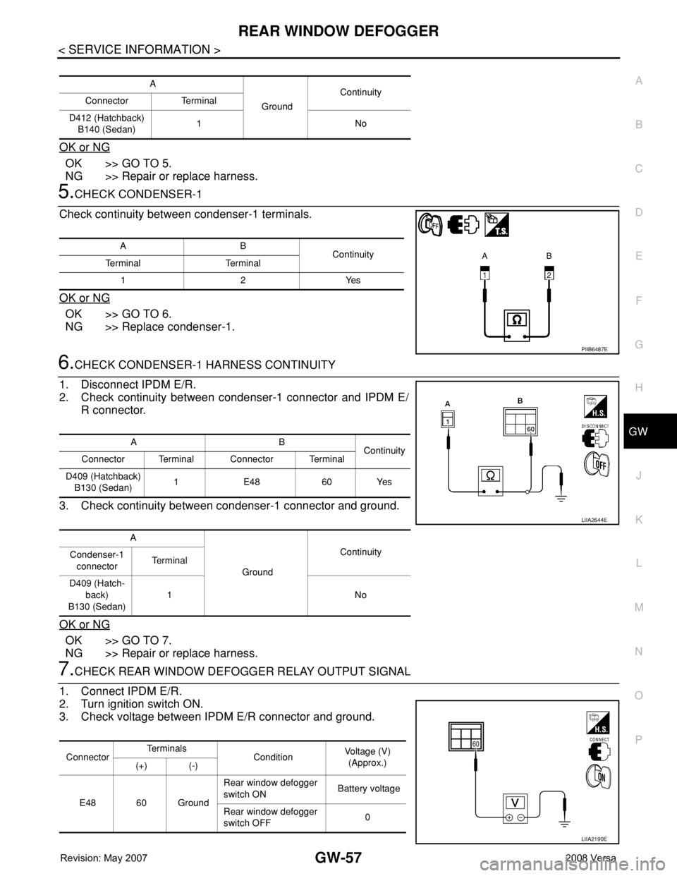
5.CHECK CONDENSER-1
Check continuity between condenser-1 terminals.
OK or NG
OK >> GO TO 6.
NG >> Replace condenser-1.
6.CHECK CONDENSER-1 HARNESS CONTINUITY
1. Disconnect IPDM E/R.
2. Check continuity between condenser-1 connector and IPDM E/
R connector.
3. Check continuity between condenser-1 connector and ground.
OK or NG
OK >> GO TO 7.
NG >> Repair or replace harness.
7.CHECK REAR WINDOW DEFOGGER RELAY OUTPUT SIGNAL
1. Connect IPDM E/R.
2. Turn ignition switch ON.
3. Check voltage between IPDM E/R connector and ground.
A
GroundContinuity
Connector Terminal
D412 (Hatchback)
B140 (Sedan)1No
AB
Continuity
Te r m i n a l Te r m i n a l
12Yes
PIIB6487E
AB
Continuity
Connector Terminal Connector Terminal
D409 (Hatchback)
B130 (Sedan)1 E48 60 Yes
A
GroundContinuity
Condenser-1
connectorTe r m i n a l
D409 (Hatch-
back)
B130 (Sedan)1No
LIIA2644E
ConnectorTe r m i n a l s
ConditionVoltage (V)
(Approx.)
(+) (-)
E48 60 GroundRear window defogger
switch ON Battery voltage
Rear window defogger
switch OFF0
LIIA2190E
Page 1959 of 2771
GW-58
< SERVICE INFORMATION >
REAR WINDOW DEFOGGER
OK or NG
OK >> Check condition of harness and connector.
NG >> Replace IPDM E/R. Refer to PG-26, "
Removal and Installation of IPDM E/R" .
Door Mirror Defogger Circuit InspectionINFOID:0000000001704178
1.CHECK FUSE
Check if the following fuse in the fuse block (J/B) is blown.
OK or NG
OK >> GO TO 2.
NG >> If fuse is blown, be sure to eliminate cause of malfunction before installing new fuse.
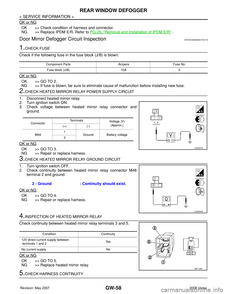
2.CHECK HEATED MIRROR RELAY POWER SUPPLY CIRCUIT
1. Disconnect heated mirror relay.
2. Turn ignition switch ON.
3. Check voltage between heated mirror relay connector and
ground.
OK or NG
OK >> GO TO 3.
NG >> Repair or replace harness.
3.CHECK HEATED MIRROR RELAY GROUND CIRCUIT
1. Turn ignition switch OFF.
2. Check continuity between heated mirror relay connector M48
terminal 2 and ground.
OK or NG
OK >> GO TO 4.
NG >> Repair or replace harness.
4.INSPECTION OF HEATED MIRROR RELAY
Check continuity between heated mirror relay terminals 3 and 5.
OK or NG
OK >> GO TO 5.
NG >> Replace heated mirror relay.
5.CHECK HARNESS CONTINUITY
Component Parts Ampere Fuse No.
Fuse block (J/B) 10A 5
ConnectorTe r m i n a l s
Voltage (V)
(Approx.)
(+) (-)
M481
Ground Battery voltage
3
LIIA2647E
2 - Ground : Continuity should exist.
LIIA2646E
Condition Continuity
12V direct current supply between
terminals 1 and 2Ye s
No current supply No
SEF145X
Page 1960 of 2771
REAR WINDOW DEFOGGER
GW-59
< SERVICE INFORMATION >
C
D
E
F
G
H
J
K
L
MA
B
GW
N
O
P
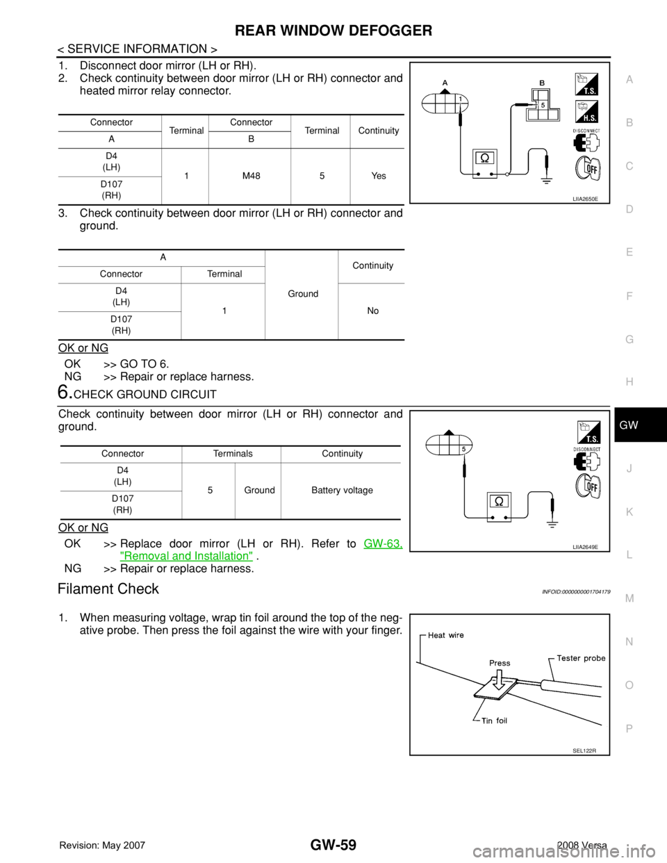
1. Disconnect door mirror (LH or RH).
2. Check continuity between door mirror (LH or RH) connector and
heated mirror relay connector.
3. Check continuity between door mirror (LH or RH) connector and
ground.
OK or NG
OK >> GO TO 6.
NG >> Repair or replace harness.
6.CHECK GROUND CIRCUIT
Check continuity between door mirror (LH or RH) connector and
ground.
OK or NG
OK >> Replace door mirror (LH or RH). Refer to GW-63,
"Removal and Installation" .
NG >> Repair or replace harness.
Filament CheckINFOID:0000000001704179
1. When measuring voltage, wrap tin foil around the top of the neg-
ative probe. Then press the foil against the wire with your finger.
Connector
Te r m i n a lConnector
Terminal Continuity
AB
D4
(LH)
1 M48 5 Yes
D107
(RH)
A
GroundContinuity
Connector Terminal
D4
(LH)
1No
D107
(RH)
LIIA2650E
Connector Terminals Continuity
D4
(LH)
5 Ground Battery voltage
D107
(RH)
LIIA2649E
SEL122R