2008 NISSAN TIIDA Engine
[x] Cancel search: EnginePage 1774 of 2771
CYLINDER BLOCK
EM-97
< SERVICE INFORMATION >
C
D
E
F
G
H
I
J
K
L
MA
EM
N
P O
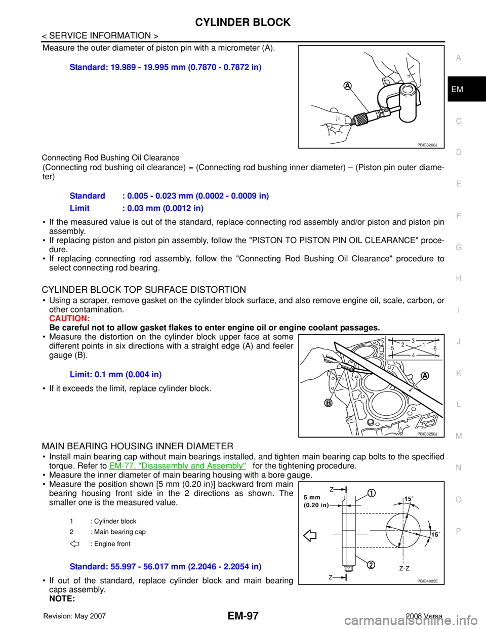
Measure the outer diameter of piston pin with a micrometer (A).
Connecting Rod Bushing Oil Clearance
(Connecting rod bushing oil clearance) = (Connecting rod bushing inner diameter) – (Piston pin outer diame-
ter)
• If the measured value is out of the standard, replace connecting rod assembly and/or piston and piston pin
assembly.
• If replacing piston and piston pin assembly, follow the "PISTON TO PISTON PIN OIL CLEARANCE" proce-
dure.
• If replacing connecting rod assembly, follow the "Connecting Rod Bushing Oil Clearance" procedure to
select connecting rod bearing.
CYLINDER BLOCK TOP SURFACE DISTORTION
• Using a scraper, remove gasket on the cylinder block surface, and also remove engine oil, scale, carbon, or
other contamination.
CAUTION:
Be careful not to allow gasket flakes to enter engine oil or engine coolant passages.
• Measure the distortion on the cylinder block upper face at some
different points in six directions with a straight edge (A) and feeler
gauge (B).
• If it exceeds the limit, replace cylinder block.
MAIN BEARING HOUSING INNER DIAMETER
• Install main bearing cap without main bearings installed, and tighten main bearing cap bolts to the specified
torque. Refer to EM-77, "
Disassembly and Assembly" for the tightening procedure.
• Measure the inner diameter of main bearing housing with a bore gauge.
• Measure the position shown [5 mm (0.20 in)] backward from main
bearing housing front side in the 2 directions as shown. The
smaller one is the measured value.
• If out of the standard, replace cylinder block and main bearing
caps assembly.
NOTE:Standard: 19.989 - 19.995 mm (0.7870 - 0.7872 in)
PBIC3266J
Standard : 0.005 - 0.023 mm (0.0002 - 0.0009 in)
Limit : 0.03 mm (0.0012 in)
Limit: 0.1 mm (0.004 in)
PBIC3250J
1 : Cylinder block
2 : Main bearing cap
: Engine front
Standard: 55.997 - 56.017 mm (2.2046 - 2.2054 in)
PBIC4005E
Page 1775 of 2771
EM-98
< SERVICE INFORMATION >
CYLINDER BLOCK
Main bearing caps cannot be replaced as a single, because it is machined together with cylinder block.
PISTON TO CYLINDER BORE CLEARANCE
Cylinder Bore Inner Diameter
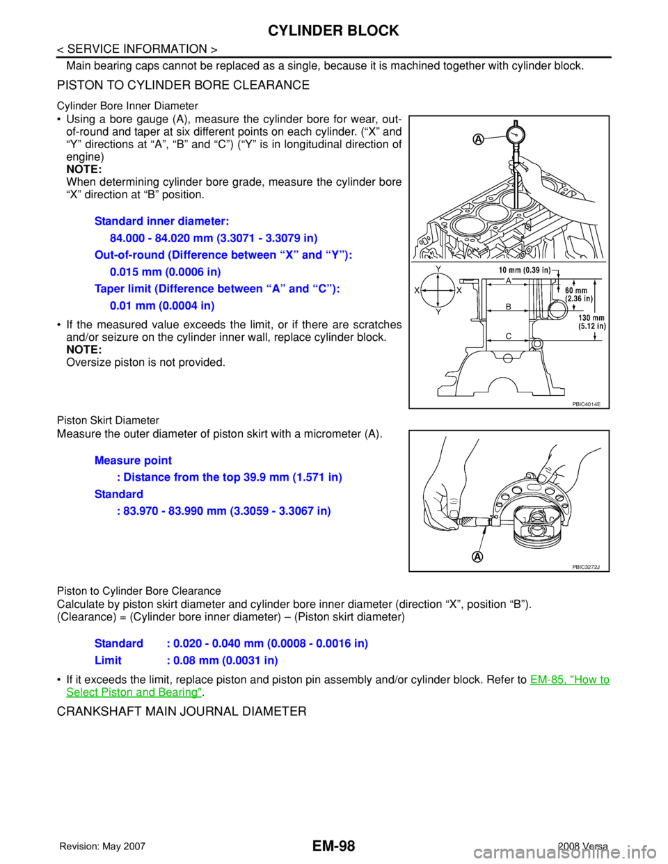
• Using a bore gauge (A), measure the cylinder bore for wear, out-
of-round and taper at six different points on each cylinder. (“X” and
“Y” directions at “A”, “B” and “C”) (“Y” is in longitudinal direction of
engine)
NOTE:
When determining cylinder bore grade, measure the cylinder bore
“X” direction at “B” position.
• If the measured value exceeds the limit, or if there are scratches
and/or seizure on the cylinder inner wall, replace cylinder block.
NOTE:
Oversize piston is not provided.
Piston Skirt Diameter
Measure the outer diameter of piston skirt with a micrometer (A).
Piston to Cylinder Bore Clearance
Calculate by piston skirt diameter and cylinder bore inner diameter (direction “X”, position “B”).
(Clearance) = (Cylinder bore inner diameter) – (Piston skirt diameter)
• If it exceeds the limit, replace piston and piston pin assembly and/or cylinder block. Refer to EM-85, "
How to
Select Piston and Bearing".
CRANKSHAFT MAIN JOURNAL DIAMETER
Standard inner diameter:
84.000 - 84.020 mm (3.3071 - 3.3079 in)
Out-of-round (Difference between “X” and “Y”):
0.015 mm (0.0006 in)
Taper limit (Difference between “A” and “C”):
0.01 mm (0.0004 in)
PBIC4014E
Measure point
: Distance from the top 39.9 mm (1.571 in)
Standard
: 83.970 - 83.990 mm (3.3059 - 3.3067 in)
PBIC3272J
Standard : 0.020 - 0.040 mm (0.0008 - 0.0016 in)
Limit : 0.08 mm (0.0031 in)
Page 1777 of 2771
EM-100
< SERVICE INFORMATION >
CYLINDER BLOCK
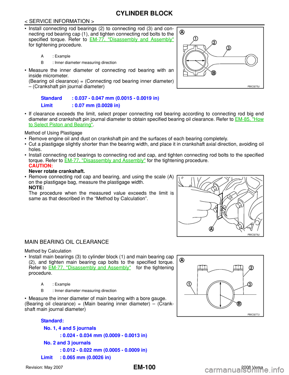
• Install connecting rod bearings (2) to connecting rod (3) and con-
necting rod bearing cap (1), and tighten connecting rod bolts to the
specified torque. Refer to EM-77, "
Disassembly and Assembly"
for tightening procedure.
• Measure the inner diameter of connecting rod bearing with an
inside micrometer.
(Bearing oil clearance) = (Connecting rod bearing inner diameter)
– (Crankshaft pin journal diameter)
• If clearance exceeds the limit, select proper connecting rod bearing according to connecting rod big end
diameter and crankshaft pin journal diameter to obtain specified bearing oil clearance. Refer to EM-85, "
How
to Select Piston and Bearing".
Method of Using Plastigage
• Remove engine oil and dust on crankshaft pin and the surfaces of each bearing completely.
• Cut a plastigage slightly shorter than the bearing width, and place it in crankshaft axial direction, avoiding oil
holes.
• Install connecting rod bearings to connecting rod and cap, and tighten connecting rod bolts to the specified
torque. Refer to EM-77, "
Disassembly and Assembly" for the tightening procedure.
CAUTION:
Never rotate crankshaft.
• Remove connecting rod cap and bearing, and using the scale (A)
on the plastigage bag, measure the plastigage width.
NOTE:
The procedure when the measured value exceeds the limit is
same as that described in the “Method by Calculation”.
MAIN BEARING OIL CLEARANCE
Method by Calculation
• Install main bearings (3) to cylinder block (1) and main bearing cap
(2), and tighten main bearing cap bolts to the specified torque.
Refer to EM-77, "
Disassembly and Assembly" for the tightening
procedure.
• Measure the inner diameter of main bearing with a bore gauge.
(Bearing oil clearance) = (Main bearing inner diameter) – (Crank-
shaft main journal diameter)
A : Example
B : Inner diameter measuring direction
Standard : 0.037 - 0.047 mm (0.0015 - 0.0019 in)
Limit : 0.07 mm (0.0028 in)
PBIC3275J
PBIC3276J
A : Example
B : Inner diameter measuring direction
Standard:
No. 1, 4 and 5 journals
: 0.024 - 0.034 mm (0.0009 - 0.0013 in)
No. 2 and 3 journals
: 0.012 - 0.022 mm (0.0005 - 0.0009 in)
Limit : 0.065 mm (0.0026 in)
PBIC3277J
Page 1778 of 2771
CYLINDER BLOCK
EM-101
< SERVICE INFORMATION >
C
D
E
F
G
H
I
J
K
L
MA
EM
N
P O
• If clearance exceeds the limit, select proper main bearing according to main bearing inner diameter and
crankshaft main journal diameter to obtain specified bearing oil clearance. Refer to EM-85, "
How to Select
Piston and Bearing".
Method of Using Plastigage
• Remove engine oil and dust on crankshaft main journal and the surfaces of each bearing completely.
• Cut a plastigage slightly shorter than the bearing width, and place it in crankshaft axial direction, avoiding oil
holes.
• Install main bearings to cylinder block and main bearing cap, and tighten main bearing cap bolts to the spec-
ified torque. Refer to EM-77, "
Disassembly and Assembly" for the tightening procedure.
CAUTION:
Never rotate crankshaft.
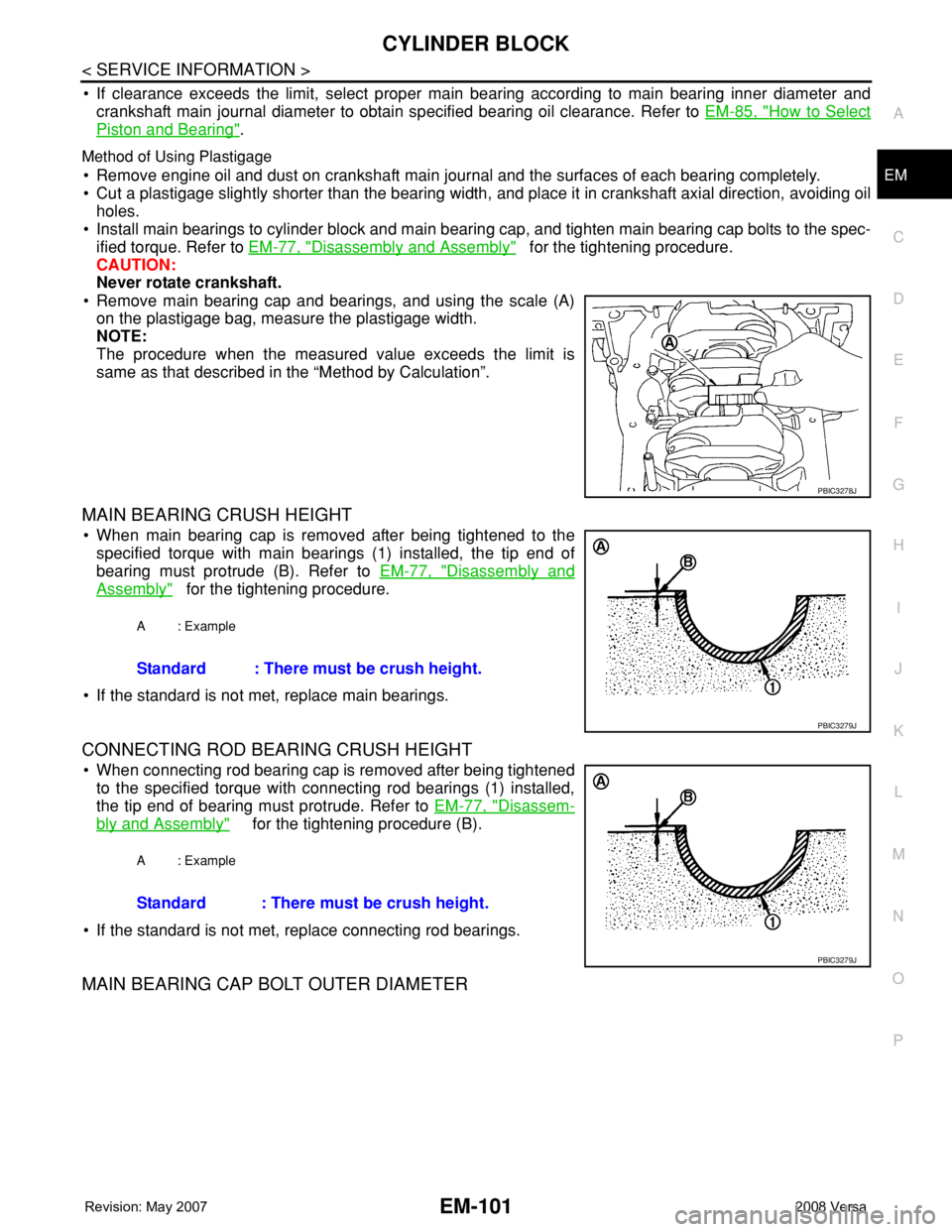
• Remove main bearing cap and bearings, and using the scale (A)
on the plastigage bag, measure the plastigage width.
NOTE:
The procedure when the measured value exceeds the limit is
same as that described in the “Method by Calculation”.
MAIN BEARING CRUSH HEIGHT
• When main bearing cap is removed after being tightened to the
specified torque with main bearings (1) installed, the tip end of
bearing must protrude (B). Refer to EM-77, "
Disassembly and
Assembly" for the tightening procedure.
• If the standard is not met, replace main bearings.
CONNECTING ROD BEARING CRUSH HEIGHT
• When connecting rod bearing cap is removed after being tightened
to the specified torque with connecting rod bearings (1) installed,
the tip end of bearing must protrude. Refer to EM-77, "
Disassem-
bly and Assembly" for the tightening procedure (B).
• If the standard is not met, replace connecting rod bearings.
MAIN BEARING CAP BOLT OUTER DIAMETER
PBIC3278J
A : Example
Standard : There must be crush height.
PBIC3279J
A : Example
Standard : There must be crush height.
PBIC3279J
Page 1781 of 2771
EM-104
< SERVICE INFORMATION >
SERVICE DATA AND SPECIFICATIONS (SDS)
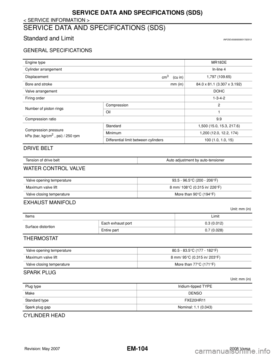
SERVICE DATA AND SPECIFICATIONS (SDS)
Standard and LimitINFOID:0000000001702513
GENERAL SPECIFICATIONS
DRIVE BELT
WATER CONTROL VALVE
EXHAUST MANIFOLD
Unit: mm (in)
THERMOSTAT
SPARK PLUG
Unit: mm (in)
CYLINDER HEAD
Engine typeMR18DE
Cylinder arrangementIn-line 4
Displacement
cm
3 (cu in)1,797 (109.65)
Bore and stroke mm (in) 84.0 x 81.1 (3.307 x 3.192)
Valve arrangementDOHC
Firing order1-3-4-2
Number of piston ringsCompression 2
Oil 1
Compression ratio9.9
Compression pressure
kPa (bar, kg/cm
2 , psi) / 250 rpmStandard 1,500 (15.0, 15.3, 217.6)
Minimum 1,200 (12.0, 12.2, 174)
Differential limit between cylinders 100 (1.0, 1.0, 15)
Tension of drive belt Auto adjustment by auto-tensioner
Valve opening temperature 93.5 - 96.5°C (200 - 206°F)
Maximum valve lift 8 mm/ 108°C (0.315 in/ 226°F)
Valve closing temperature More than 90°C (194°F)
Items Limit
Surface distortionEach exhaust port 0.3 (0.012)
Entire part 0.7 (0.028)
Valve opening temperature 80.5 - 83.5°C (177 - 182°F)
Maximum valve lift 8 mm/ 95°C (0.315 in/ 203°F)
Valve closing temperature More than 77°C (171°F)
Plug typeIridium-tipped TYPE
MakeDENSO
Standard typeFXE20HR11
Spark plug gapNominal: 1.1 (0.043)
Page 1792 of 2771
EX-1
ENGINE
C
D
E
F
G
H
I
J
K
L
M
SECTION EX
A
EX
N
O
P
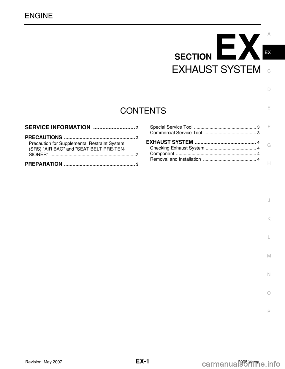
CONTENTS
EXHAUST SYSTEM
SERVICE INFORMATION ............................2
PRECAUTIONS ...................................................2
Precaution for Supplemental Restraint System
(SRS) "AIR BAG" and "SEAT BELT PRE-TEN-
SIONER" ...................................................................
2
PREPARATION ...................................................3
Special Service Tool .................................................3
Commercial Service Tool .........................................3
EXHAUST SYSTEM ...........................................4
Checking Exhaust System ........................................4
Component ...............................................................4
Removal and Installation ..........................................4
Page 1796 of 2771
EXHAUST SYSTEM
EX-5
< SERVICE INFORMATION >
C
D
E
F
G
H
I
J
K
L
MA
EX
N
P O
• Be sure to use genuine NISSAN exhaust system parts or equivalents which are specially designed
for heat resistance, corrosion resistance and shape.
• Perform the operation with the exhaust system fully cooled down because the system will be hot
just after the engine stops.
• Be careful not to cut your hand on heat insulator edge.
1. Disconnect harness connector of heated oxygen sensor 2.
• Using Tool, remove heated oxygen sensor 2.
CAUTION:
Be careful not to damage heated oxygen sensor 2.
a.2. Disconnect each joint and mounting rubber.
INSTALLATION
Installation is in the reverse order of removal.
CAUTION:
• Always replace exhaust gaskets and seal bearings with new ones when installing.
• Discard any heated oxygen sensor 2 which has been dropped from a height of more than 0.5 m (19.7
in) onto a hard surface such as a concrete floor; use a new one.
• Before installing a new heated oxygen sensor 2, clean exhaust system threads using the heated oxy-
gen sensor thread cleaner and apply anti-seize lubricant (commercial service tool).
• Do not over tighten heated oxygen sensor 2. Doing so may cause damage to the heated oxygen sen-
sor 2, resulting in the “MIL” coming on.
• Remove deposits from the sealing surface of each connection. Connect them securely to avoid
exhaust leakage.
• Temporarily tighten nuts on the exhaust manifold side and bolts on the vehicle side. Check each part
for unusual interference, and then tighten them to the specified torque.
• When installing each mounting rubber, avoid twisting or unusual extension in up/down and right/left
directions.
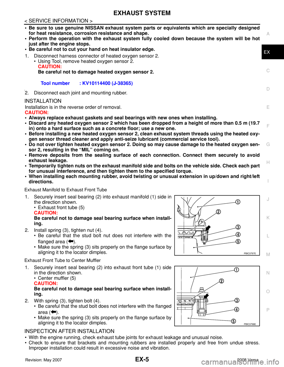
Exhaust Manifold to Exhaust Front Tube
1. Securely insert seal bearing (2) into exhaust manifold (1) side in
the direction shown.
• Exhaust front tube (5)
CAUTION:
Be careful not to damage seal bearing surface when install-
ing.
2. Install spring (3), tighten nut (4).
• Be careful that the stud bolt nut does not interfere with the
flanged area ( ).
• Make sure the spring (3) sits properly on the flange surface by
aligning it to the locator dimples.
Exhaust Front Tube to Center Muffler
1. Securely insert seal bearing (2) into exhaust front tube (1) side
in the direction shown.
• Center muffler (5)
CAUTION:
Be careful not to damage seal bearing surface when install-
ing.
2. With spring (3), tighten bolt (4).
• Be careful that the stud bolt does not interfere with the flanged
area ( ).
• Make sure the spring (3) sits properly on the flange surface by
aligning it to the locator dimples.
INSPECTION AFTER INSTALLATION
• With the engine running, check exhaust tube joints for exhaust leakage and unusual noise.
• Check to ensure that brackets and mounting rubbers are installed properly and free from undue stress.
Improper installation could result in excessive noise and vibration.Tool number : KV10114400 (J-38365)
PBIC3797E
PBIC3798E
Page 1821 of 2771
FL-1
ENGINE
C
D
E
F
G
H
I
J
K
L
M
SECTION FL
A
FL
N
O
P
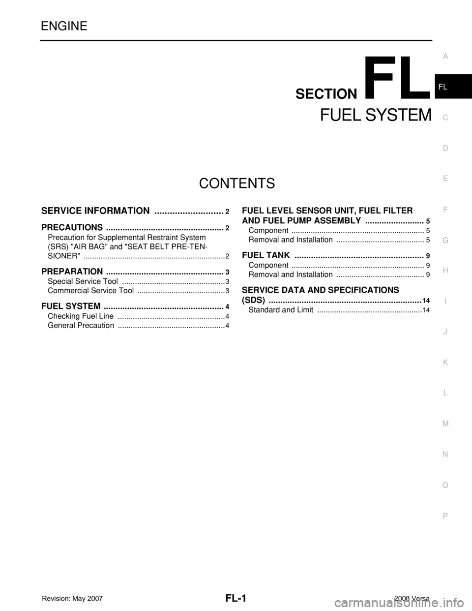
CONTENTS
FUEL SYSTEM
SERVICE INFORMATION ............................2
PRECAUTIONS ...................................................2
Precaution for Supplemental Restraint System
(SRS) "AIR BAG" and "SEAT BELT PRE-TEN-
SIONER" ...................................................................
2
PREPARATION ...................................................3
Special Service Tool .................................................3
Commercial Service Tool ..........................................3
FUEL SYSTEM ....................................................4
Checking Fuel Line ...................................................4
General Precaution ...................................................4
FUEL LEVEL SENSOR UNIT, FUEL FILTER
AND FUEL PUMP ASSEMBLY .........................
5
Component ...............................................................5
Removal and Installation ..........................................5
FUEL TANK .......................................................9
Component ...............................................................9
Removal and Installation ..........................................9
SERVICE DATA AND SPECIFICATIONS
(SDS) .................................................................
14
Standard and Limit ..................................................14