2008 NISSAN TIIDA brake sensor
[x] Cancel search: brake sensorPage 1281 of 2771

DTC P0130 A/F SENSOR 1
EC-207
< SERVICE INFORMATION >
C
D
E
F
G
H
I
J
K
L
MA
EC
N
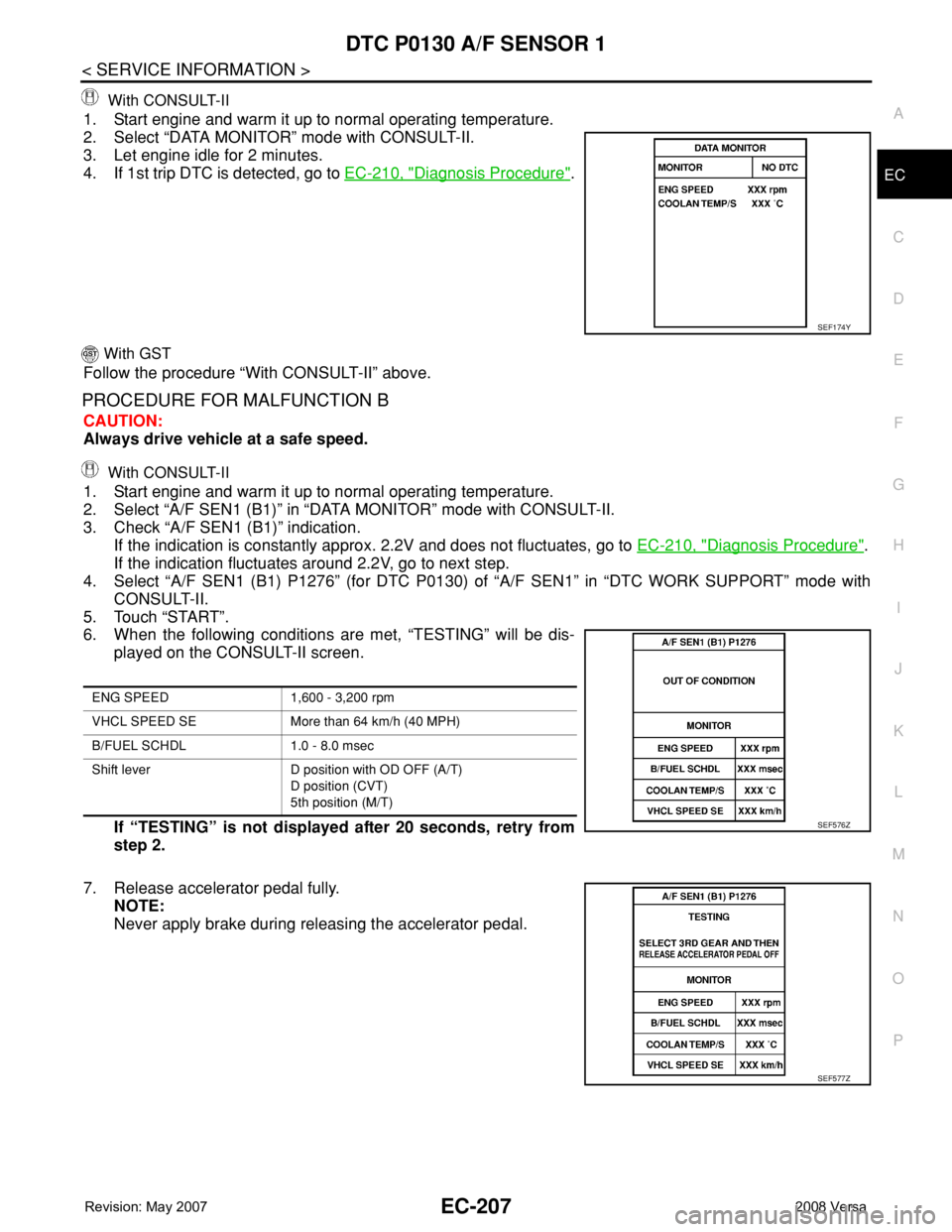
P O With CONSULT-II
1. Start engine and warm it up to normal operating temperature.
2. Select “DATA MONITOR” mode with CONSULT-II.
3. Let engine idle for 2 minutes.
4. If 1st trip DTC is detected, go to EC-210, "
Diagnosis Procedure".
With GST
Follow the procedure “With CONSULT-II” above.
PROCEDURE FOR MALFUNCTION B
CAUTION:
Always drive vehicle at a safe speed.
With CONSULT-II
1. Start engine and warm it up to normal operating temperature.
2. Select “A/F SEN1 (B1)” in “DATA MONITOR” mode with CONSULT-II.
3. Check “A/F SEN1 (B1)” indication.
If the indication is constantly approx. 2.2V and does not fluctuates, go to EC-210, "
Diagnosis Procedure".
If the indication fluctuates around 2.2V, go to next step.
4. Select “A/F SEN1 (B1) P1276” (for DTC P0130) of “A/F SEN1” in “DTC WORK SUPPORT” mode with
CONSULT-II.
5. Touch “START”.
6. When the following conditions are met, “TESTING” will be dis-
played on the CONSULT-II screen.
If “TESTING” is not displayed after 20 seconds, retry from
step 2.
7. Release accelerator pedal fully.
NOTE:
Never apply brake during releasing the accelerator pedal.
SEF174Y
ENG SPEED 1,600 - 3,200 rpm
VHCL SPEED SE More than 64 km/h (40 MPH)
B/FUEL SCHDL 1.0 - 8.0 msec
Shift lever D position with OD OFF (A/T)
D position (CVT)
5th position (M/T)
SEF576Z
SEF577Z
Page 1282 of 2771

EC-208
< SERVICE INFORMATION >
DTC P0130 A/F SENSOR 1
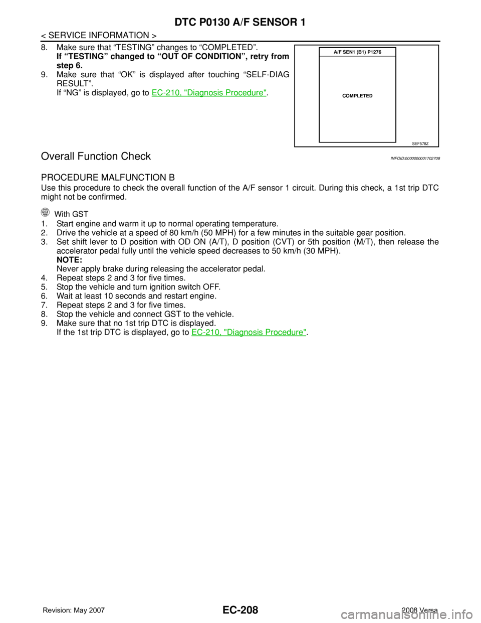
8. Make sure that “TESTING” changes to “COMPLETED”.
If “TESTING” changed to “OUT OF CONDITION”, retry from
step 6.
9. Make sure that “OK” is displayed after touching “SELF-DIAG
RESULT”.
If “NG” is displayed, go to EC-210, "
Diagnosis Procedure".
Overall Function CheckINFOID:0000000001702708
PROCEDURE MALFUNCTION B
Use this procedure to check the overall function of the A/F sensor 1 circuit. During this check, a 1st trip DTC
might not be confirmed.
With GST
1. Start engine and warm it up to normal operating temperature.
2. Drive the vehicle at a speed of 80 km/h (50 MPH) for a few minutes in the suitable gear position.
3. Set shift lever to D position with OD ON (A/T), D position (CVT) or 5th position (M/T), then release the
accelerator pedal fully until the vehicle speed decreases to 50 km/h (30 MPH).
NOTE:
Never apply brake during releasing the accelerator pedal.
4. Repeat steps 2 and 3 for five times.
5. Stop the vehicle and turn ignition switch OFF.
6. Wait at least 10 seconds and restart engine.
7. Repeat steps 2 and 3 for five times.
8. Stop the vehicle and connect GST to the vehicle.
9. Make sure that no 1st trip DTC is displayed.
If the 1st trip DTC is displayed, go to EC-210, "
Diagnosis Procedure".
SEF578Z
Page 1802 of 2771

FAX-6
< SERVICE INFORMATION >
FRONT WHEEL HUB AND KNUCKLE
2. Without disassembling the hydraulic lines, remove the torque member bolts using power tool. Then repo-
sition the torque member and brake caliper assembly aside with wire. Refer to BR-23
.
CAUTION:
Do not depress brake pedal while brake caliper is removed.
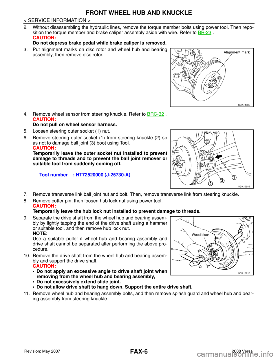
3. Put alignment marks on disc rotor and wheel hub and bearing
assembly, then remove disc rotor.
4. Remove wheel sensor from steering knuckle. Refer to BRC-32
.
CAUTION:
Do not pull on wheel sensor harness.
5. Loosen steering outer socket (1) nut.
6. Remove steering outer socket (1) from steering knuckle (2) so
as not to damage ball joint (3) boot using Tool.
CAUTION:
Temporarily leave the outer socket nut installed to prevent
damage to threads and to prevent the ball joint remover or
suitable tool from suddenly coming off.
7. Remove transverse link ball joint nut and bolt. Then, remove transverse link from steering knuckle.
8. Remove cotter pin, then loosen hub lock nut using power tool.
CAUTION:
Temporarily leave the hub lock nut installed to prevent damage to threads.
9. Separate the drive shaft from the wheel hub and bearing assem-
bly by lightly tapping the end of the drive shaft using a hammer
or suitable tool, and then remove hub lock nut.
NOTE:
Use a suitable puller if wheel hub and bearing assembly and
drive shaft cannot be separated after performing the above pro-
cedure.
10. Remove the drive shaft from the wheel hub and bearing assem-
bly and support the drive shaft.
CAUTION:
• Do not apply an excessive angle to drive shaft joint when
removing from the wheel hub and bearing assembly,
• Do not excessively extend slide joint.
• Do not allow drive shaft to hang down. Support the entire drive shaft.
11. Remove wheel hub and bearing assembly bolts, and then remove splash guard and wheel hub and bear-
ing assembly from steering knuckle.
SDIA1480E
Tool number : HT72520000 (J-25730-A)
SGIA1298E
SDIA1821E
Page 1845 of 2771

COIL SPRING AND STRUT
FSU-11
< SERVICE INFORMATION >
C
D
F
G
H
I
J
K
L
MA
B
FSU
N
O
P
COIL SPRING AND STRUT
Removal and InstallationINFOID:0000000001703725
REMOVAL
1. Remove cowl top panel. Refer to EI-21 .
2. Remove front tires using power tool.
3. Remove harness of wheel sensor from strut assembly. Refer to BRC-32
.
CAUTION:
Do not pull on wheel sensor harness.
4. Remove brake hose lock plate. Refer to BR-10
.
5. Remove the nut on the upper side of stabilizer connecting rod using power tool, and then remove stabi-
lizer connecting rod from strut assembly.
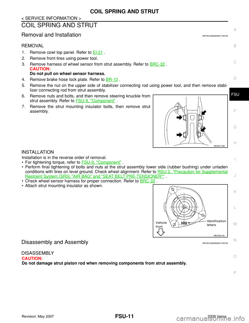
6. Remove nuts and bolts, and then remove steering knuckle from
strut assembly. Refer to FSU-9, "
Component" .
7. Remove the strut mounting insulator bolts, then remove strut
assembly.
INSTALLATION
Installation is in the reverse order of removal.
• For tightening torque, refer to FSU-9, "
Component" .
• Perform final tightening of bolts and nuts at the strut assembly lower side (rubber bushing) under unladen
conditions with tires on level ground. Check wheel alignment. Refer to RSU-2, "
Precaution for Supplemental
Restraint System (SRS) "AIR BAG" and "SEAT BELT PRE-TENSIONER"" .
• Check wheel sensor harness for proper connection. Refer to BRC-32
.
• Attach strut mounting insulator as shown.
Disassembly and AssemblyINFOID:0000000001703726
DISASSEMBLY
CAUTION:
Do not damage strut piston rod when removing components from strut assembly.
WEIA0179E
MEIA0014E
Page 1860 of 2771

HOW TO USE THIS MANUAL
GI-9
< SERVICE INFORMATION >
C
D
E
F
G
H
I
J
K
L
MB
GI
N
O
P
SYMBOLS
How to Follow Trouble DiagnosisINFOID:0000000001702437
DESCRIPTION
NOTICE:
Trouble diagnoses indicate work procedures required to diagnose problems effectively. Observe the following
instructions before diagnosing.
1.Before performing trouble diagnoses, read the “Preliminary Check”, the “Symptom Chart” or the
“Work Flow”.
2.After repairs, re-check that the problem has been completely eliminated.
1. Union bolt 2. Copper washer 3. Brake hose
4. Cap 5. Bleed valve 6. Sliding pin bolt
7. Piston seal 8. Piston 9. Piston boot
10. Cylinder body 11. Sliding pin 12. Torque member mounting bolt
13. Washer 14. Sliding pin boot 15. Bushing
16. Torque member 17. Inner shim cover 18. Inner shim
19. Inner pad 20. Pad retainer 21. Pad wear sensor
22. Outer pad 23. Outer shim 24. Outer shim cover
1: PBC (Poly Butyl Cuprysil) grease
or silicone-based grease2: Rubber grease : Brake fluid
Refer to GI section for additional symbol definitions.
SFIA2959E
SAIA0749E
Page 2016 of 2771
![NISSAN TIIDA 2008 Service Repair Manual CAN COMMUNICATION SYSTEM
LAN-25
< FUNCTION DIAGNOSIS >[CAN]
C
D
E
F
G
H
I
J
L
MA
B
LAN
N
O
P
*1: A/T models
*2: CVT models
*3: Models for Canada
*4: Models for USA
*5: Models without ABS
NOTE:
CAN dat NISSAN TIIDA 2008 Service Repair Manual CAN COMMUNICATION SYSTEM
LAN-25
< FUNCTION DIAGNOSIS >[CAN]
C
D
E
F
G
H
I
J
L
MA
B
LAN
N
O
P
*1: A/T models
*2: CVT models
*3: Models for Canada
*4: Models for USA
*5: Models without ABS
NOTE:
CAN dat](/manual-img/5/57399/w960_57399-2015.png)
CAN COMMUNICATION SYSTEM
LAN-25
< FUNCTION DIAGNOSIS >[CAN]
C
D
E
F
G
H
I
J
L
MA
B
LAN
N
O
P
*1: A/T models
*2: CVT models
*3: Models for Canada
*4: Models for USA
*5: Models without ABS
NOTE:
CAN data of the air bag diagnosis sensor unit is not used by usual service work, thus it is omitted.
Brake warning lamp signal R T
A/T check indicator signal R T
A/T self-diagnosis signal R T
OD OFF indicator signal R T
Output shaft revolution signal R T T
Shift position indicator signal R T T
Turbine revolution signal R T
CVT self-diagnosis signal R T
Input shaft revolution signal R T
OD OFF indicator signal R T
Front wiper stop position signal R T
High beam status signal RT
Low beam status signal RT
Oil pressure switch signal R T
Rear window defogger control signal RT Signal name/Connecting unit
ECM
BCM
EPS
I-KEY
M&A
ABS
TCM
*1
TCM
*2
IPDM-E
Page 2472 of 2771

HARNESS
PG-39
< SERVICE INFORMATION >
C
D
E
F
G
H
I
J
L
MA
B
PG
N
O
P
C2 M6 W/4 : Steering lock solenoid E2 M52 W/40 : Intelligent key unit
B3 M7 W/16 : Door mirror remote control switch B2 M53 W/16 : EPS control unit
A3 M8 W/16 : To D2 B3 M54 B/2 : EPS control unit
A3 M9 W/16 : To D1 C3 M55† W/4: Hazard switch (hatchback early
production)
E2 M10 GR/2 : Instrument panel antenna D2 M55†† W/4: Hazard switch (hatchback late production
or sedan)
G3 M11 W/4 : To B106 B2 M57 — : Body ground
G4 M12 W/16 : To B101 F2 M59 W/2 : Glove box lamp
G3 M13 W/24 : To B102 C1 M60 L/2 : EPS control unit
G3 M14 W/24 : To B120 F1 M61 — : Body ground
B4 M15 W/16 : To B23 E2 M62 W/2 : Front blower motor
B4 M16 W/24 : To B24 C1 M63 W/4 : Torque sensor
D5 M17 B/1 : Parking brake switch A2 M69 SMJ : To E7
F2 M18 W/40 : BCM (body control module) B2 M73 GR/6: Key switch and ignition knob switch (With
intelligent key)
F2 M19 W/15 : BCM (body control module) G3 M74 W/12 : To D102
F3 M20 B/15 : BCM (body control module) G3 M75 W/12 : To D101
C2 M21 W/4 : NATS antenna amp. F2 M77 Y/4 : Front passenger air bag module
B3 M22 W/16 : Data link connector A2 M78 B/2 : To E11
E3 M23 W/4 : Remote keyless entry receiver B1 M79 — : Body ground
C1 M24 W/40 : Combination meter D3 M150 W/4 : To M32
C3 M25 /2 : Diode-1 C3 M151 W/4 : Front blower motor resistor
B2 M26 W/6 : Ignition switch
C2 M27 GR/6 : Key switch and key lock solenoid
C2 M28 W/16 : Combination switch
C3 M29 Y/6 : Combination switch (spiral cable)
C3 M30 GR/8 : Combination switch (spiral cable)
E3 M32 W/4 : To M150
D2 M33 B/15 : Front air control
D4 M35 Y/28 : Air bag diagnosis sensor unit
D2 M36† W/3: Front passenger air bag OFF indicator
(hatchback early production)
C3 M36†† W/3: Front passenger air bag OFF indicator
(hatchback late production or sedan)
D4 M38 W/6 : A/T device
D4 M38 W/6 : CVT device (without intelligent key)
D4 M38 W/8 : CVT device (with intelligent key)
B3 M39 W/2 : Tire pressure warning check connector
D2 M41 W/2 : Defrost A/C switch
D3 M42 W/3 : Thermo control amp. (without CVT)
D2 M43 W/20 : Audio unit
Page 2474 of 2771

HARNESS
PG-41
< SERVICE INFORMATION >
C
D
E
F
G
H
I
J
L
MA
B
PG
N
O
P
C3 E6 — : Fuse and fusible link box D3 E53 B/2: Front combination lamp LH
(parking)
B1 E7 SMJ : To M69
D3 E8 SMJ : To F8
B4 E9 BR/2 : Fusible link box (battery)
B3 E10 GR/2 : Fusible link box (battery)
B1 E11 B/2 : To M78
A3 E12 B/6 : Accelerator pedal position sensor
A2 E13 B/2 : Stop lamp switch (with M/T)
A2 E13 W/4 : Stop lamp switch (without M/T)
D3 E14 — : Engine ground (crash zone sensor)
C2 E15 — : Engine ground
B2 E16 B/32 : ECM
C5 E18 B/1 : Horn (low)
C4 E19 GR/6 : To F33
D5 E20 B/1 : Horn (low)
D3 E25 B/3: Front combination lamp LH
(headlamp)
E4 E27 B/2 : Front fog lamp LH
D4 E29 B/2: Front combination lamp LH
(turn signal)
B1 E31 W/24 : TCM
B1 E32 GR/24 : TCM
A2 E34 BR/2 : Clutch interlock switch (with M/T)
A2 E35 BR/2 : ASCD clutch switch
A2 E36 BR/2 : ASCD brake switch
B4 E40 GR/2 : Brake fluid level switch
D3 E42 B/2: IPDM E/R (Intelligent Power Distribu-
tion Module Engine Room)
C3 E43 W/16: IPDM E/R (Intelligent Power Distribu-
tion Module Engine Room)
C3 E44 W/6: IPDM E/R (Intelligent Power Distribu-
tion Module Engine Room)
D3 E45 BR/12: IPDM E/R (Intelligent Power Distribu-
tion Module Engine Room)
D3 E46 W/12: IPDM E/R (Intelligent Power Distribu-
tion Module Engine Room)