Page 1854 of 2771
PRECAUTIONS
GI-3
< SERVICE INFORMATION >
C
D
E
F
G
H
I
J
K
L
MB
GI
N
O
P
General PrecautionINFOID:0000000001702424
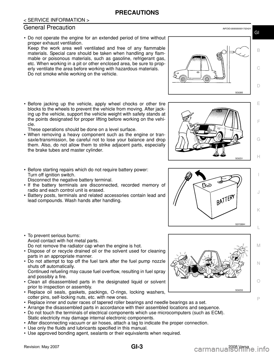
• Do not operate the engine for an extended period of time without
proper exhaust ventilation.
Keep the work area well ventilated and free of any flammable
materials. Special care should be taken when handling any flam-
mable or poisonous materials, such as gasoline, refrigerant gas,
etc. When working in a pit or other enclosed area, be sure to prop-
erly ventilate the area before working with hazardous materials.
Do not smoke while working on the vehicle.
• Before jacking up the vehicle, apply wheel chocks or other tire
blocks to the wheels to prevent the vehicle from moving. After jack-
ing up the vehicle, support the vehicle weight with safety stands at
the points designated for proper lifting before working on the vehi-
cle.
These operations should be done on a level surface.
• When removing a heavy component such as the engine or tran-
saxle/transmission, be careful not to lose your balance and drop
them. Also, do not allow them to strike adjacent parts, especially
the brake tubes and master cylinder.
• Before starting repairs which do not require battery power:
Turn off ignition switch.
Disconnect the negative battery terminal.
• If the battery terminals are disconnected, recorded memory of
radio and each control unit is erased.
• Battery posts, terminals and related accessories contain lead and
lead compounds. Wash hands after handling.
• To prevent serious burns:
Avoid contact with hot metal parts.
Do not remove the radiator cap when the engine is hot.
• Dispose of or recycle drained oil or the solvent used for cleaning
parts in an appropriate manner.
• Do not attempt to top off the fuel tank after the fuel pump nozzle
shuts off automatically.
Continued refueling may cause fuel overflow, resulting in fuel spray
and possibly a fire.
• Clean all disassembled parts in the designated liquid or solvent
prior to inspection or assembly.
• Replace oil seals, gaskets, packings, O-rings, locking washers,
cotter pins, self-locking nuts, etc. with new ones.
• Replace inner and outer races of tapered roller bearings and needle bearings as a set.
• Arrange the disassembled parts in accordance with their assembled locations and sequence.
• Do not touch the terminals of electrical components which use microcomputers (such as ECM).
Static electricity may damage internal electronic components.
• After disconnecting vacuum or air hoses, attach a tag to indicate the proper connection.
• Use only the fluids and lubricants specified in this manual.
• Use approved bonding agent, sealants or their equivalents when required.
SGI285
SGI231
SEF289H
SGI233
Page 1884 of 2771
SERVICE INFORMATION FOR ELECTRICAL INCIDENT
GI-33
< SERVICE INFORMATION >
C
D
E
F
G
H
I
J
K
L
MB
GI
N
O
P
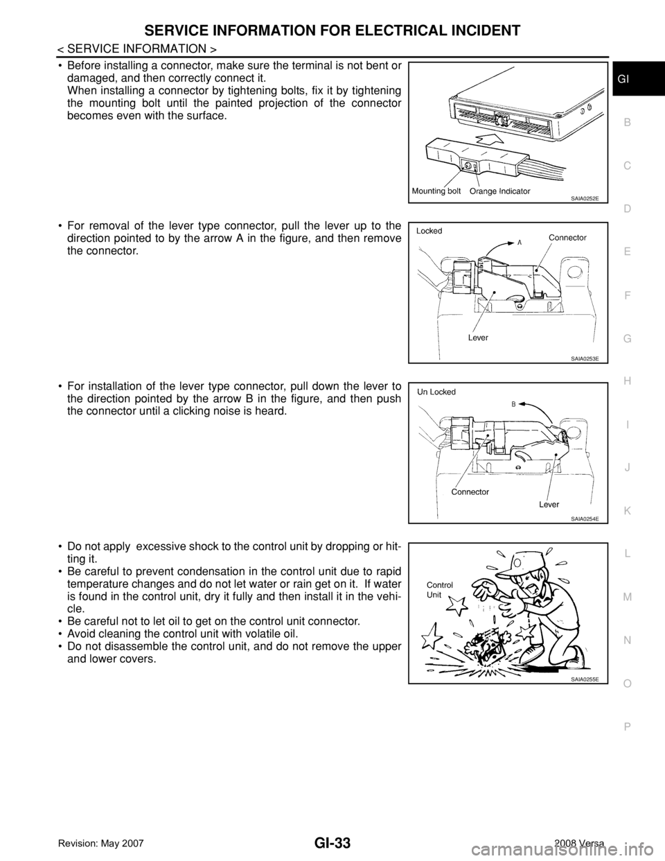
• Before installing a connector, make sure the terminal is not bent or
damaged, and then correctly connect it.
When installing a connector by tightening bolts, fix it by tightening
the mounting bolt until the painted projection of the connector
becomes even with the surface.
• For removal of the lever type connector, pull the lever up to the
direction pointed to by the arrow A in the figure, and then remove
the connector.
• For installation of the lever type connector, pull down the lever to
the direction pointed by the arrow B in the figure, and then push
the connector until a clicking noise is heard.
• Do not apply excessive shock to the control unit by dropping or hit-
ting it.
• Be careful to prevent condensation in the control unit due to rapid
temperature changes and do not let water or rain get on it. If water
is found in the control unit, dry it fully and then install it in the vehi-
cle.
• Be careful not to let oil to get on the control unit connector.
• Avoid cleaning the control unit with volatile oil.
• Do not disassemble the control unit, and do not remove the upper
and lower covers.
SAIA0252E
SAIA0253E
SAIA0254E
SAIA0255E
Page 1964 of 2771
DOOR MIRROR
GW-63
< SERVICE INFORMATION >
C
D
E
F
G
H
J
K
L
MA
B
GW
N
O
P
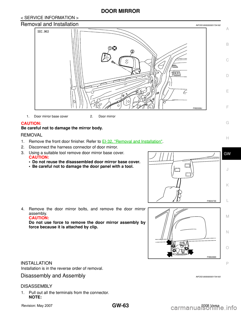
Removal and InstallationINFOID:0000000001704182
CAUTION:
Be careful not to damage the mirror body.
REMOVAL
1. Remove the front door finisher. Refer to EI-32, "Removal and Installation".
2. Disconnect the harness connector of door mirror.
3. Using a suitable tool remove door mirror base cover.
CAUTION:
• Do not reuse the disassembled door mirror base cover.
• Be careful not to damage the door panel with a tool.
4. Remove the door mirror bolts, and remove the door mirror
assembly.
CAUTION:
Do not use force to remove the door mirror assembly by
force because it is attached by clip.
INSTALLATION
Installation is in the reverse order of removal.
Disassembly and AssemblyINFOID:0000000001704183
DISASSEMBLY
1. Pull out all the terminals from the connector.
NOTE:
PIIB2638J
1. Door mirror base cover 2. Door mirror
PIIB2679E
PIIB6288E
Page 1966 of 2771
INSIDE MIRROR
GW-65
< SERVICE INFORMATION >
C
D
E
F
G
H
J
K
L
MA
B
GW
N
O
P
INSIDE MIRROR
Removal and InstallationINFOID:0000000001704184
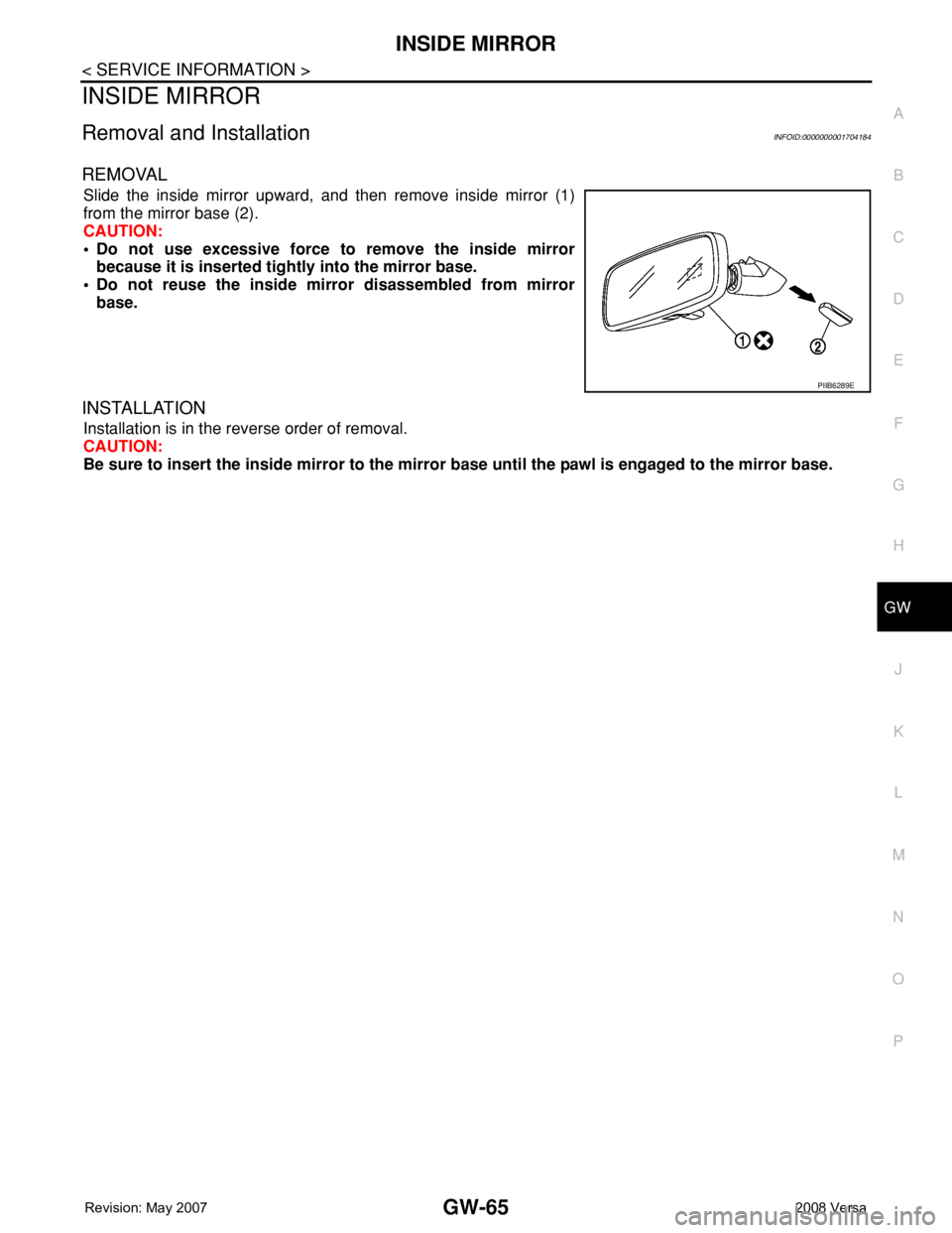
REMOVAL
Slide the inside mirror upward, and then remove inside mirror (1)
from the mirror base (2).
CAUTION:
• Do not use excessive force to remove the inside mirror
because it is inserted tightly into the mirror base.
• Do not reuse the inside mirror disassembled from mirror
base.
INSTALLATION
Installation is in the reverse order of removal.
CAUTION:
Be sure to insert the inside mirror to the mirror base until the pawl is engaged to the mirror base.
PIIB6289E
Page 2277 of 2771
ENGINE MAINTENANCE
MA-17
< SERVICE INFORMATION >
C
D
E
F
G
H
I
J
K
MA
B
MA
N
O
P
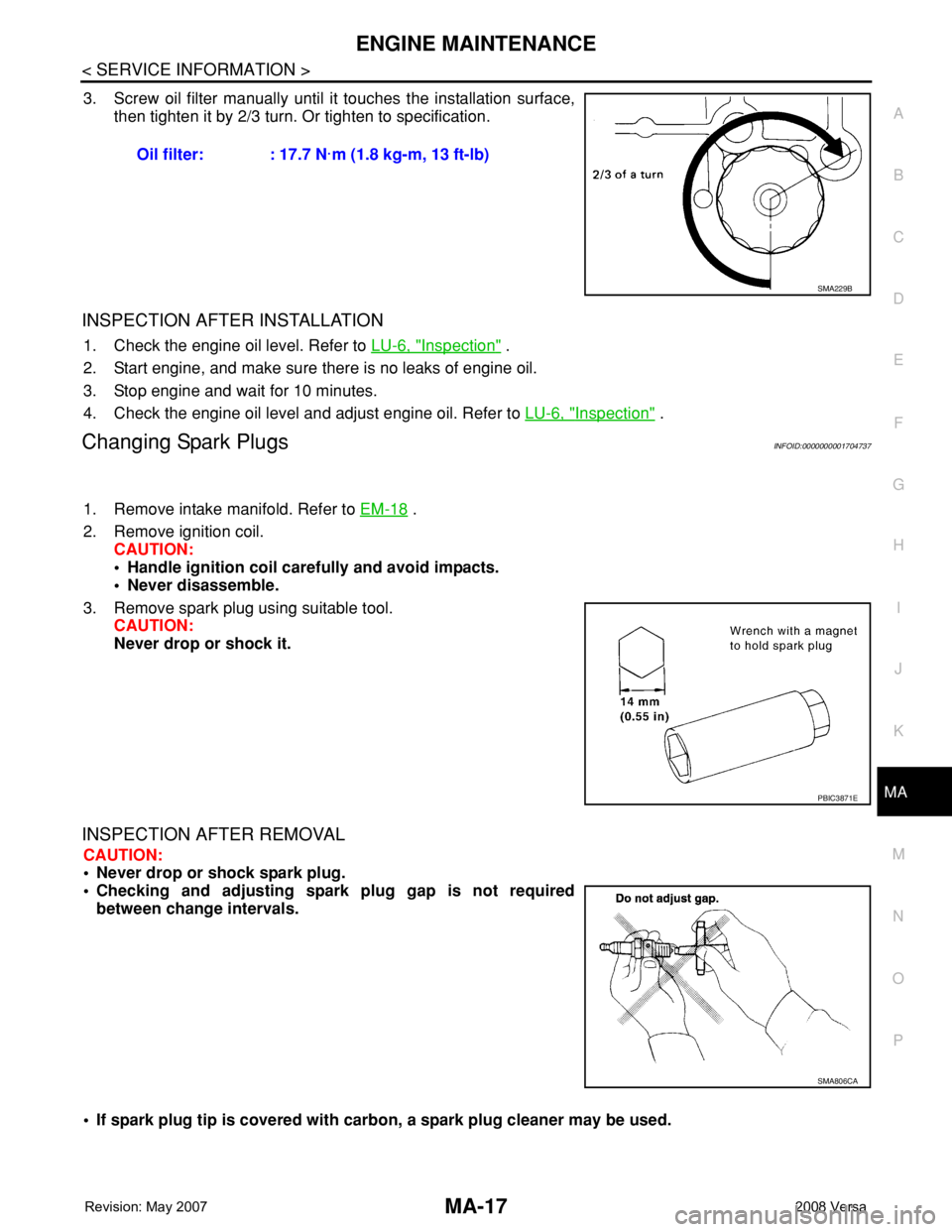
3. Screw oil filter manually until it touches the installation surface,
then tighten it by 2/3 turn. Or tighten to specification.
INSPECTION AFTER INSTALLATION
1. Check the engine oil level. Refer to LU-6, "Inspection" .
2. Start engine, and make sure there is no leaks of engine oil.
3. Stop engine and wait for 10 minutes.
4. Check the engine oil level and adjust engine oil. Refer to LU-6, "
Inspection" .
Changing Spark PlugsINFOID:0000000001704737
1. Remove intake manifold. Refer to EM-18 .
2. Remove ignition coil.
CAUTION:
• Handle ignition coil carefully and avoid impacts.
• Never disassemble.
3. Remove spark plug using suitable tool.
CAUTION:
Never drop or shock it.
INSPECTION AFTER REMOVAL
CAUTION:
• Never drop or shock spark plug.
• Checking and adjusting spark plug gap is not required
between change intervals.
• If spark plug tip is covered with carbon, a spark plug cleaner may be used. Oil filter: : 17.7 N·m (1.8 kg-m, 13 ft-lb)
SMA229B
PBIC3871E
SMA806CA
Page 2278 of 2771
MA-18
< SERVICE INFORMATION >
ENGINE MAINTENANCE
• Never use wire brush for cleaning spark plug.
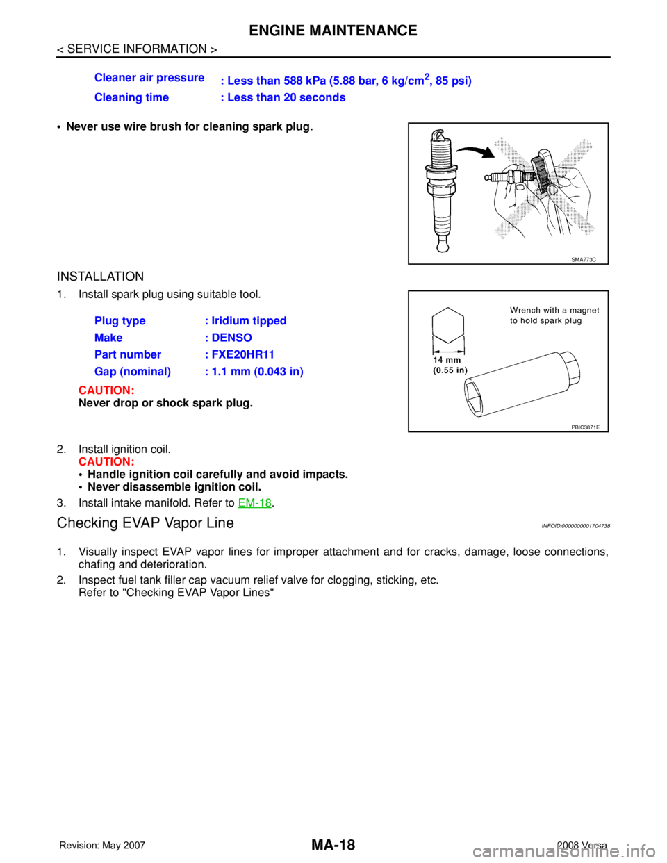
INSTALLATION
1. Install spark plug using suitable tool.
CAUTION:
Never drop or shock spark plug.
2. Install ignition coil.
CAUTION:
• Handle ignition coil carefully and avoid impacts.
• Never disassemble ignition coil.
3. Install intake manifold. Refer to EM-18
.
Checking EVAP Vapor LineINFOID:0000000001704738
1. Visually inspect EVAP vapor lines for improper attachment and for cracks, damage, loose connections,
chafing and deterioration.
2. Inspect fuel tank filler cap vacuum relief valve for clogging, sticking, etc.
Refer to "Checking EVAP Vapor Lines"Cleaner air pressure
: Less than 588 kPa (5.88 bar, 6 kg/cm
2, 85 psi)
Cleaning time : Less than 20 seconds
SMA773C
Plug type : Iridium tipped
Make : DENSO
Part number : FXE20HR11
Gap (nominal) : 1.1 mm (0.043 in)
PBIC3871E
Page 2323 of 2771
INPUT SHAFT AND GEARS
MT-35
< SERVICE INFORMATION >
D
E
F
G
H
I
J
K
L
MA
B
MT
N
O
P
INPUT SHAFT AND GEARS
Disassembly and AssemblyINFOID:0000000001703143
GENERAL PRECAUTIONS
• Do not reuse snap ring.
• Position input shaft on the vise with back plate and remove gears and snap rings.
• For installation and removal of snap ring, position snap ring pliers
and flat pliers at both sides of snap ring. Stretch snap ring, and
move it with flat pliers.
• Disassemble gear components putting matching marks on the
parts that do not affect any functions.
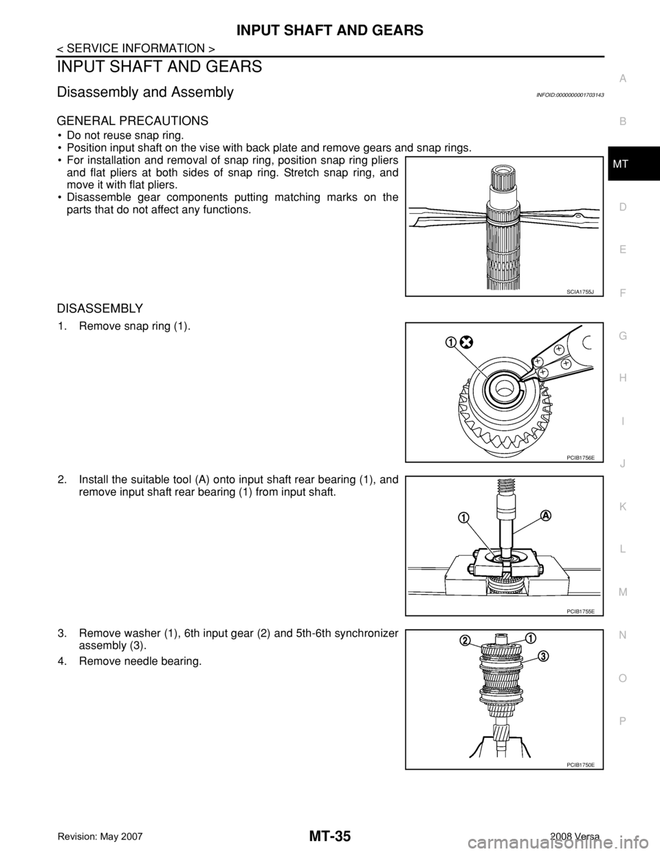
DISASSEMBLY
1. Remove snap ring (1).
2. Install the suitable tool (A) onto input shaft rear bearing (1), and
remove input shaft rear bearing (1) from input shaft.
3. Remove washer (1), 6th input gear (2) and 5th-6th synchronizer
assembly (3).
4. Remove needle bearing.
SCIA1755J
PCIB1756E
PCIB1755E
PCIB1750E
Page 2327 of 2771
MAINSHAFT AND GEARS
MT-39
< SERVICE INFORMATION >
D
E
F
G
H
I
J
K
L
MA
B
MT
N
O
P
MAINSHAFT AND GEARS
Disassembly and AssemblyINFOID:0000000001703144
GENERAL PRECAUTIONS
• Do not reuse snap rings.
• Position mainshaft on the vise with back plate and remove gears and snap rings.
• For installation and removal of snap ring, position snap ring pliers
and flat pliers at both sides of snap ring. Stretch snap ring, and
move it with flat pliers.
• Disassemble gear components putting matching marks on the
parts that do not affect any functions.
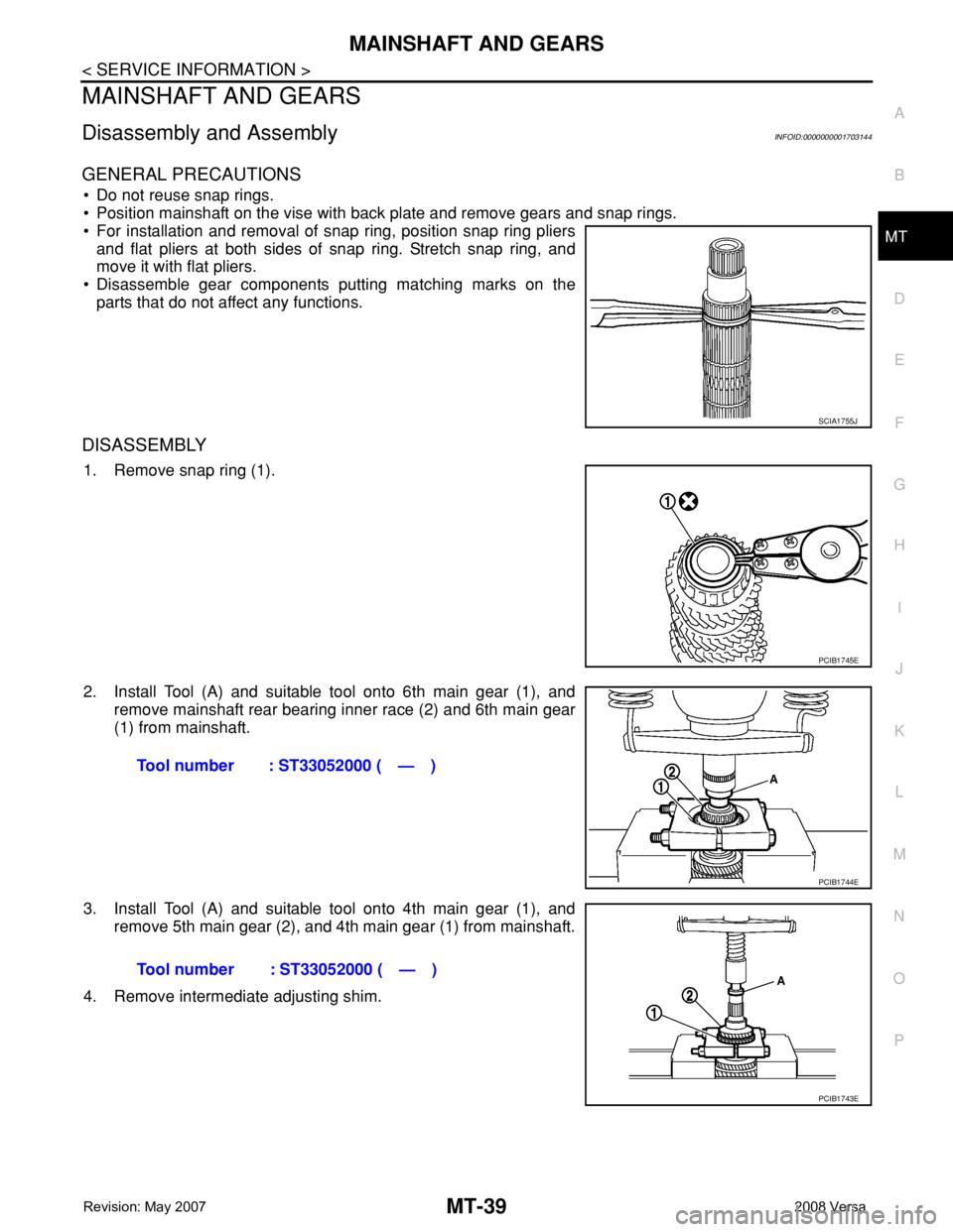
DISASSEMBLY
1. Remove snap ring (1).
2. Install Tool (A) and suitable tool onto 6th main gear (1), and
remove mainshaft rear bearing inner race (2) and 6th main gear
(1) from mainshaft.
3. Install Tool (A) and suitable tool onto 4th main gear (1), and
remove 5th main gear (2), and 4th main gear (1) from mainshaft.
4. Remove intermediate adjusting shim.
SCIA1755J
PCIB1745E
Tool number : ST33052000 ( — )
PCIB1744E
Tool number : ST33052000 ( — )
PCIB1743E