2008 NISSAN TIIDA DISASSEMBLE
[x] Cancel search: DISASSEMBLEPage 229 of 2771
ON-VEHICLE SERVICE
AT-217
< SERVICE INFORMATION >
D
E
F
G
H
I
J
K
L
MA
B
AT
N
O
P
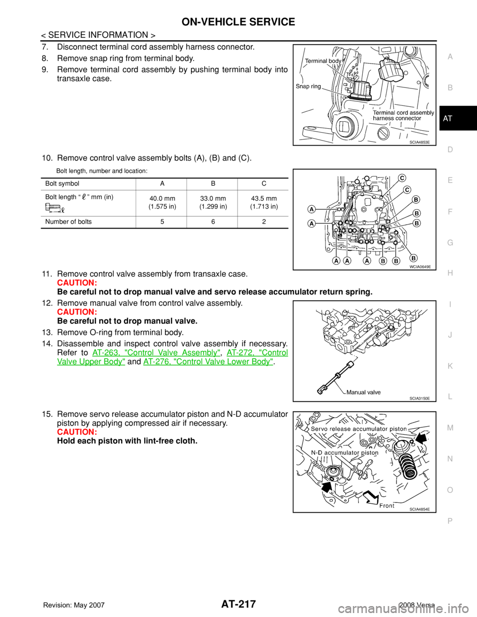
7. Disconnect terminal cord assembly harness connector.
8. Remove snap ring from terminal body.
9. Remove terminal cord assembly by pushing terminal body into
transaxle case.
10. Remove control valve assembly bolts (A), (B) and (C).
Bolt length, number and location:
11. Remove control valve assembly from transaxle case.
CAUTION:
Be careful not to drop manual valve and servo release accumulator return spring.
12. Remove manual valve from control valve assembly.
CAUTION:
Be careful not to drop manual valve.
13. Remove O-ring from terminal body.
14. Disassemble and inspect control valve assembly if necessary.
Refer to AT-263, "
Control Valve Assembly", AT-272, "Control
Valve Upper Body" and AT-276, "Control Valve Lower Body".
15. Remove servo release accumulator piston and N-D accumulator
piston by applying compressed air if necessary.
CAUTION:
Hold each piston with lint-free cloth.
SCIA4853E
Bolt symbol A B C
Bolt length “ ” mm (in)
40.0 mm
(1.575 in)33.0 mm
(1.299 in)43.5 mm
(1.713 in)
Number of bolts 5 6 2
WCIA0649E
SCIA3150E
SCIA4854E
Page 266 of 2771
AT-254
< SERVICE INFORMATION >
DISASSEMBLY
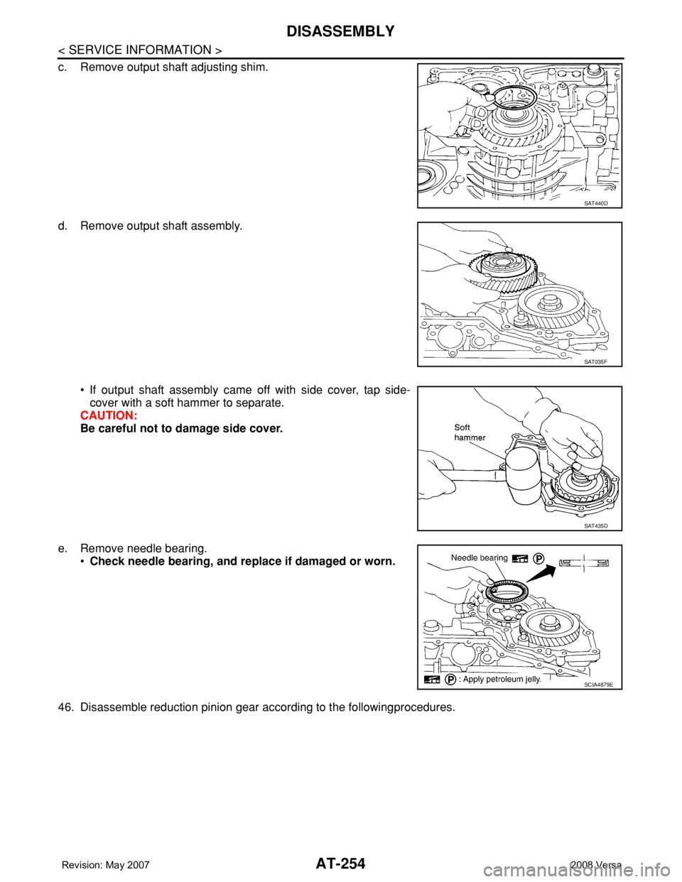
c. Remove output shaft adjusting shim.
d. Remove output shaft assembly.
• If output shaft assembly came off with side cover, tap side-
cover with a soft hammer to separate.
CAUTION:
Be careful not to damage side cover.
e. Remove needle bearing.
•Check needle bearing, and replace if damaged or worn.
46. Disassemble reduction pinion gear according to the followingprocedures.
SAT440D
SAT035F
SAT435D
SCIA4879E
Page 741 of 2771
BR-10
< SERVICE INFORMATION >
BRAKE TUBE AND HOSE
BRAKE TUBE AND HOSE
Hydraulic CircuitINFOID:0000000001703784
CAUTION:
• All tubes and hoses must be free from excessive bending, twisting and pulling.
• Make sure there is no interference with other parts when turning steering both clockwise and coun-
terclockwise.
• Brake tubes and hoses are an important safety part. Always disassemble the parts and retighten
their fittings, if a brake fluid leak is detected. Replace applicable part with a new one, if damaged part
is detected.
• Be careful not to splash brake fluid on painted areas; it way cause paint damage. If brake fluid is
splashed on painted surfaces of body, immediately wipe them with cloth and then wash it away with
water.
• Do not bend or twist brake hose sharply, or strongly pull it.
• When removing components, cover brake line connections so that dirt, dust, or other foreign mat-
ters do not get in.
• Refill using recommended brake fluid. Refer to MA-10
.
• Never reuse drained brake fluid.
Front Brake Tube and HoseINFOID:0000000001703785
REMOVAL
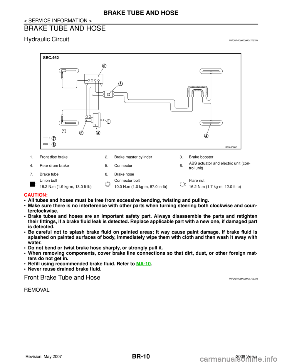
1. Front disc brake 2. Brake master cylinder 3. Brake booster
4. Rear drum brake 5. Connector 6.ABS actuator and electric unit (con-
trol unit)
7. Brake tube 8. Brake hose
:Union bolt
:Connector bolt
:Flare nut
18.2 N.m (1.9 kg-m, 13.0 ft-lb) 10.0 N.m (1.0 kg-m, 87.0 in-lb) 16.2 N.m (1.7 kg-m, 12.0 ft-lb)
SFIA3068E
Page 742 of 2771
BRAKE TUBE AND HOSE
BR-11
< SERVICE INFORMATION >
C
D
E
G
H
I
J
K
L
MA
B
BR
N
O
P
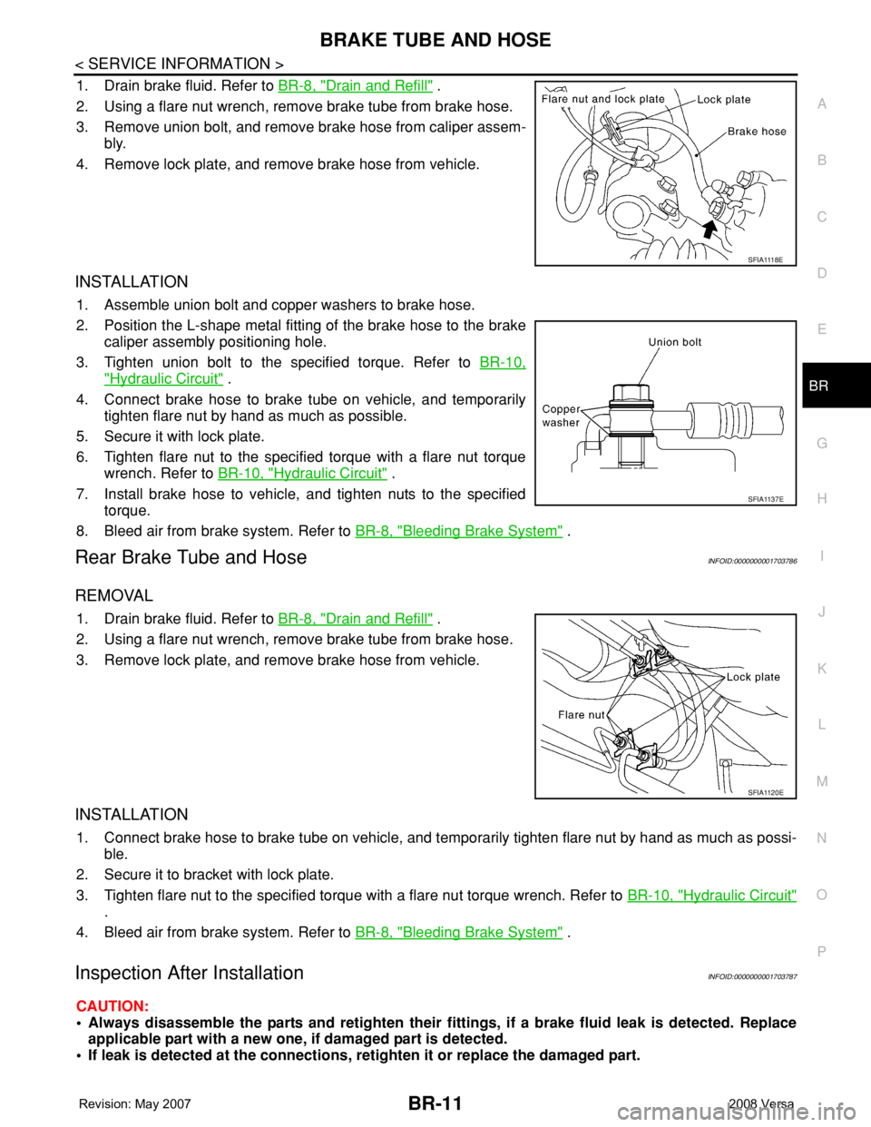
1. Drain brake fluid. Refer to BR-8, "Drain and Refill" .
2. Using a flare nut wrench, remove brake tube from brake hose.
3. Remove union bolt, and remove brake hose from caliper assem-
bly.
4. Remove lock plate, and remove brake hose from vehicle.
INSTALLATION
1. Assemble union bolt and copper washers to brake hose.
2. Position the L-shape metal fitting of the brake hose to the brake
caliper assembly positioning hole.
3. Tighten union bolt to the specified torque. Refer to BR-10,
"Hydraulic Circuit" .
4. Connect brake hose to brake tube on vehicle, and temporarily
tighten flare nut by hand as much as possible.
5. Secure it with lock plate.
6. Tighten flare nut to the specified torque with a flare nut torque
wrench. Refer to BR-10, "
Hydraulic Circuit" .
7. Install brake hose to vehicle, and tighten nuts to the specified
torque.
8. Bleed air from brake system. Refer to BR-8, "
Bleeding Brake System" .
Rear Brake Tube and HoseINFOID:0000000001703786
REMOVAL
1. Drain brake fluid. Refer to BR-8, "Drain and Refill" .
2. Using a flare nut wrench, remove brake tube from brake hose.
3. Remove lock plate, and remove brake hose from vehicle.
INSTALLATION
1. Connect brake hose to brake tube on vehicle, and temporarily tighten flare nut by hand as much as possi-
ble.
2. Secure it to bracket with lock plate.
3. Tighten flare nut to the specified torque with a flare nut torque wrench. Refer to BR-10, "
Hydraulic Circuit"
.
4. Bleed air from brake system. Refer to BR-8, "
Bleeding Brake System" .
Inspection After InstallationINFOID:0000000001703787
CAUTION:
• Always disassemble the parts and retighten their fittings, if a brake fluid leak is detected. Replace
applicable part with a new one, if damaged part is detected.
• If leak is detected at the connections, retighten it or replace the damaged part.
S F I A 111 8 E
SFIA1137E
SFIA1120E
Page 761 of 2771
BR-30
< SERVICE INFORMATION >
REAR DRUM BRAKE
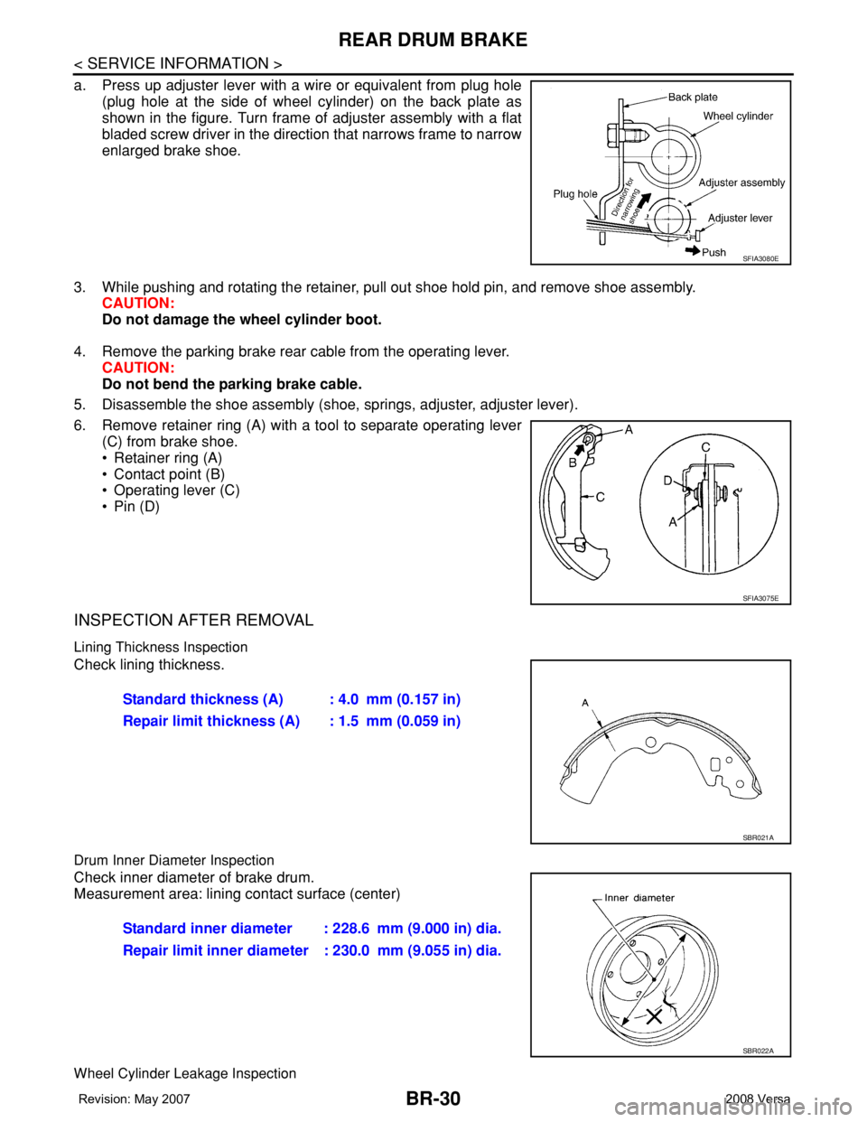
a. Press up adjuster lever with a wire or equivalent from plug hole
(plug hole at the side of wheel cylinder) on the back plate as
shown in the figure. Turn frame of adjuster assembly with a flat
bladed screw driver in the direction that narrows frame to narrow
enlarged brake shoe.
3. While pushing and rotating the retainer, pull out shoe hold pin, and remove shoe assembly.
CAUTION:
Do not damage the wheel cylinder boot.
4. Remove the parking brake rear cable from the operating lever.
CAUTION:
Do not bend the parking brake cable.
5. Disassemble the shoe assembly (shoe, springs, adjuster, adjuster lever).
6. Remove retainer ring (A) with a tool to separate operating lever
(C) from brake shoe.
• Retainer ring (A)
• Contact point (B)
• Operating lever (C)
•Pin (D)
INSPECTION AFTER REMOVAL
Lining Thickness Inspection
Check lining thickness.
Drum Inner Diameter Inspection
Check inner diameter of brake drum.
Measurement area: lining contact surface (center)
Wheel Cylinder Leakage Inspection
SFIA3080E
SFIA3075E
Standard thickness (A) : 4.0 mm (0.157 in)
Repair limit thickness (A) : 1.5 mm (0.059 in)
SBR021A
Standard inner diameter : 228.6 mm (9.000 in) dia.
Repair limit inner diameter : 230.0 mm (9.055 in) dia.
SBR022A
Page 762 of 2771
REAR DRUM BRAKE
BR-31
< SERVICE INFORMATION >
C
D
E
G
H
I
J
K
L
MA
B
BR
N
O
P
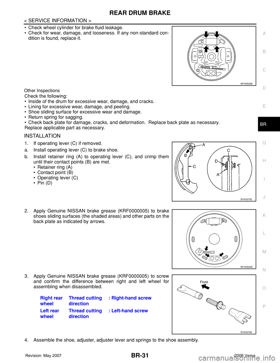
• Check wheel cylinder for brake fluid leakage.
• Check for wear, damage, and looseness. If any non-standard con-
dition is found, replace it.
Other Inspections
Check the following:
• Inside of the drum for excessive wear, damage, and cracks.
• Lining for excessive wear, damage, and peeling.
• Shoe sliding surface for excessive wear and damage.
• Return spring for sagging.
• Check back plate for damage, cracks, and deformation. Replace back plate as necessary.
Replace applicable part as necessary.
INSTALLATION
1. If operating lever (C) if removed.
a. Install operating lever (C) to brake shoe.
b. Install retainer ring (A) to operating lever (C), and crimp them
until their contact points (B) are met.
• Retainer ring (A)
• Contact point (B)
• Operating lever (C)
•Pin (D)
2. Apply Genuine NISSAN brake grease (KRF0000005) to brake
shoes sliding surfaces (the shaded areas) and other parts on the
back plate as indicated by arrows.
3. Apply Genuine NISSAN brake grease (KRF0000005) to screw
and confirm the difference between right and left wheel for
assembling when disassembled.
4. Assemble the shoe, adjuster, adjuster lever and springs to the shoe assembly.
WFIA0528E
SFIA3075E
WFIA0529E
Right rear
wheelThread cutting
direction: Right-hand screw
Left rear
wheelThread cutting
direction: Left-hand screw
SFIA3076E
Page 767 of 2771
![NISSAN TIIDA 2008 Service Repair Manual BRC-2
< SERVICE INFORMATION >[ABS]
PRECAUTIONS
SERVICE INFORMATION
PRECAUTIONS
Precaution for Supplemental Restraint System (SRS) "AIR BAG" and "SEAT BELT
PRE-TENSIONER"
INFOID:000000](/manual-img/5/57399/w960_57399-766.png "NISSAN TIIDA 2008 Service Repair Manual BRC-2
< SERVICE INFORMATION >[ABS]
PRECAUTIONS
SERVICE INFORMATION
PRECAUTIONS
Precaution for Supplemental Restraint System (SRS) \"AIR BAG\" and \"SEAT BELT
PRE-TENSIONER\"
INFOID:000000")
BRC-2
< SERVICE INFORMATION >[ABS]
PRECAUTIONS
SERVICE INFORMATION
PRECAUTIONS
Precaution for Supplemental Restraint System (SRS) "AIR BAG" and "SEAT BELT
PRE-TENSIONER"
INFOID:0000000001703818
The Supplemental Restraint System such as “AIR BAG” and “SEAT BELT PRE-TENSIONER”, used along
with a front seat belt, helps to reduce the risk or severity of injury to the driver and front passenger for certain
types of collision. This system includes seat belt switch inputs and dual stage front air bag modules. The SRS
system uses the seat belt switches to determine the front air bag deployment, and may only deploy one front
air bag, depending on the severity of a collision and whether the front occupants are belted or unbelted.
Information necessary to service the system safely is included in the SRS and SB section of this Service Man-
ual.
WARNING:
• To avoid rendering the SRS inoperative, which could increase the risk of personal injury or death in
the event of a collision which would result in air bag inflation, all maintenance must be performed by
an authorized NISSAN/INFINITI dealer.
• Improper maintenance, including incorrect removal and installation of the SRS, can lead to personal
injury caused by unintentional activation of the system. For removal of Spiral Cable and Air Bag
Module, see the SRS section.
• Do not use electrical test equipment on any circuit related to the SRS unless instructed to in this
Service Manual. SRS wiring harnesses can be identified by yellow and/or orange harnesses or har-
ness connectors.
Precaution for Brake SystemINFOID:0000000001703819
CAUTION:
• Refer to MA-10
for recommended brake fluid.
• Never reuse drained brake fluid.
• Be careful not to splash brake fluid on painted areas; it may cause paint damage. If brake fluid is
splashed on painted areas, wash it away with water immediately.
• To clean or wash all parts of master cylinder and disc brake caliper, use clean brake fluid.
• Never use mineral oils such as gasoline or kerosene. They will ruin rubber parts of the hydraulic sys-
tem.
• Use flare nut wrench when removing and installing brake
tube.
• If a brake fluid leak is found, the part must be disassembled
without fail. Then it has to be replaced with a new one if a
defect exists.
• Turn the ignition switch OFF and remove the connector of the
ABS actuator and electric unit (control unit) or the battery ter-
minal before performing the work.
• Always torque brake lines when installing.
• Burnish the brake contact surfaces after refinishing or replac-
ing rotors, after replacing pads, or if a soft pedal occurs at
very low mileage. Refer to BR-28, "
Brake Burnishing Proce-
dure".
WARNING:
• Clean brake pads and shoes with a waste cloth, then wipe with a dust collector.
Precaution for Brake ControlINFOID:0000000001703821
• During ABS operation, the brake pedal may vibrate lightly and a mechanical noise may be heard. This is
normal.
• Just after starting the vehicle, the brake pedal may vibrate or motor operating noises may be heard from
engine compartment. This is normal due to the self check operation.
• Stopping distance may be longer than that of vehicles without ABS when vehicle drives on rough, gravel, or
snow-covered (fresh, deep snow) roads.
SBR686C
Page 782 of 2771
![NISSAN TIIDA 2008 Service Repair Manual TROUBLE DIAGNOSIS
BRC-17
< SERVICE INFORMATION >[ABS]
C
D
E
G
H
I
J
K
L
MA
B
BRC
N
O
P
• If ABS actuator and electric unit (control unit) connection is loose, tighten the piping to the specified
tor](/manual-img/5/57399/w960_57399-781.png "NISSAN TIIDA 2008 Service Repair Manual TROUBLE DIAGNOSIS
BRC-17
< SERVICE INFORMATION >[ABS]
C
D
E
G
H
I
J
K
L
MA
B
BRC
N
O
P
• If ABS actuator and electric unit (control unit) connection is loose, tighten the piping to the specified
tor")
TROUBLE DIAGNOSIS
BRC-17
< SERVICE INFORMATION >[ABS]
C
D
E
G
H
I
J
K
L
MA
B
BRC
N
O
P
• If ABS actuator and electric unit (control unit) connection is loose, tighten the piping to the specified
torque and recheck for leaks.
• If there is damage to the connection flare nut or ABS actuator and electric unit (control unit) threads,
replace the damaged part and recheck for leaks.
• When there is fluid leaking or seeping from a fluid connection, use a clean cloth to wipe off the fluid and
recheck for leaks. If fluid is still seeping out, replace the damaged part. If the fluid is leaking at the ABS
actuator and electric unit (control unit), replace the ABS actuator and electric unit (control unit) assem-
bly.
CAUTION:
The ABS actuator and electric unit (control unit) cannot be disassembled and must be replaced
as an assembly.
3. Check the brake pads for excessive wear.
POWER SYSTEM TERMINAL LOOSENESS AND BATTERY INSPECTION
Make sure the battery positive cable, negative cable and ground connection are not loose. In addition, make
sure the battery is sufficiently charged.
ABS WARNING LAMP INSPECTION
1. Make sure ABS warning lamp turns on for approximately 2 seconds when the ignition switch is turned ON.
If it does not, check CAN communications. If there are no errors with the CAN communication system,
replace the combination meter. Refer to IP-11, "
Removal and Installation".
2. Make sure the lamp turns off approximately 2 seconds after the ignition switch is turned ON. If the lamp
does not turn off, conduct self-diagnosis of ABS actuator and electric unit (control unit). If no malfunctions
are detected in self-diagnosis, replace combination meter. Refer to IP-11, "
Removal and Installation".
3. After conducting the self-diagnosis, be sure to erase the error memory. Refer to BRC-18, "
CONSULT-III
Function (ABS)".
Warning Lamp and Indicator TimingINFOID:0000000001703836
Note 1: Brake warning lamp will turn on when the parking brake is applied or when the brake fluid level is low.
x: ON
–: OFF
Control Unit Input/Output Signal StandardINFOID:0000000001703837
REFERENCE VALUE FROM CONSULT-III
CAUTION:
The display shows the control unit calculation data, so a normal value might be displayed even in the
event the output circuit (harness) is open or short circuited.
ConditionABS
warning lampBRAKE
warning lamp
[Note 1]Remarks
When the ignition switch is OFF – – –
After the ignition switch is turned ON for approx. 1
second××–
After the ignition switch is turned ON for approx. 2
seconds––Lamp goes off approx. 2 seconds after the
engine is started.
ABS malfunction×––
EBD malfunction××–