2008 NISSAN TIIDA indicator
[x] Cancel search: indicatorPage 212 of 2771
AT-200
< SERVICE INFORMATION >
TROUBLE DIAGNOSIS FOR SYMPTOMS
- Shift valve A
- Overrun clutch solenoid valve
3. Disassemble A/T. Refer to AT-240, "
Disassembly" .
4. Check the following.
- Overrun clutch assembly. Refer to AT-288, "
Forward and Overrun Clutches" .
- Low & reverse brake assembly. Refer to AT-295, "
Low & Reverse Brake" .
OK or NG
OK >> GO TO 10.
NG >> Repair or replace damaged parts.
10.CHECK SYMPTOM
Check again. Refer to AT-59, "
Cruise Test - Part 3" .
OK or NG
OK >>INSPECTION END
NG >> GO TO 11.
11 .CHECK TCM
1. Check TCM input/output signals. Refer to AT-71, "
TCM Terminal and Reference Value" .
2. If NG, recheck TCM pin terminals for damage or loose connection with harness connector.
OK or NG
OK >> INSPECTION END
NG >> Repair or replace damaged parts.
TCM Self-Diagnosis Does Not ActivateINFOID:0000000001703354
SYMPTOM:
OD OFF indicator lamp does not come on in TCM self-diagnostic procedure even if the lamp circuit is
good.
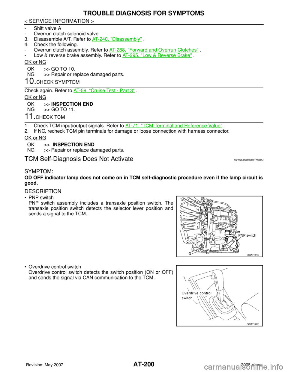
DESCRIPTION
• PNP switch
PNP switch assembly includes a transaxle position switch. The
transaxle position switch detects the selector lever position and
sends a signal to the TCM.
• Overdrive control switch
Overdrive control switch detects the switch position (ON or OFF)
and sends the signal via CAN communication to the TCM.
SCIA7141E
SCIA7142E
Page 215 of 2771
SHIFT CONTROL SYSTEM
AT-203
< SERVICE INFORMATION >
D
E
F
G
H
I
J
K
L
MA
B
AT
N
O
P
SHIFT CONTROL SYSTEM
Control Device Removal and InstallationINFOID:0000000001703356
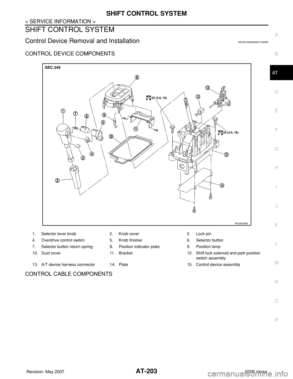
CONTROL DEVICE COMPONENTS
CONTROL CABLE COMPONENTS
1. Selector lever knob 2. Knob cover 3. Lock pin
4. Overdrive control switch 5. Knob finisher 6. Selector button
7. Selector button return spring 8. Position indicator plate 9. Position lamp
10. Dust cover 11. Bracket 12. Shift lock solenoid and park position
switch assembly
13. A/T device harness connector 14. Plate 15. Control device assembly
WCIA0638E
Page 218 of 2771
AT-206
< SERVICE INFORMATION >
SHIFT CONTROL SYSTEM
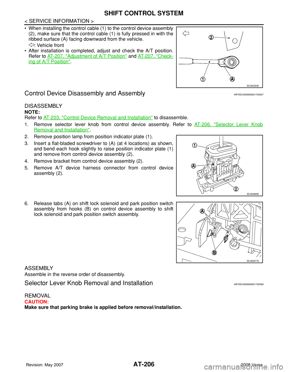
• When installing the control cable (1) to the control device assembly
(2), make sure that the control cable (1) is fully pressed in with the
ribbed surface (A) facing downward from the vehicle.
: Vehicle front
• After installation is completed, adjust and check the A/T position.
Refer to AT-207, "
Adjustment of A/T Position" and AT-207, "Check-
ing of A/T Position".
Control Device Disassembly and AssemblyINFOID:0000000001703357
DISASSEMBLY
NOTE:
Refer to AT-203, "
Control Device Removal and Installation" to disassemble.
1. Remove selector lever knob from control device assembly. Refer to AT-206, "
Selector Lever Knob
Removal and Installation".
2. Remove position lamp from position indicator plate (1).
3. Insert a flat-bladed screwdriver to (A) (at 4 locations) as shown,
and bend each hook slightly to raise position indicator plate (1)
and remove from control device assembly (2).
4. Remove bracket from control device assembly (2).
5. Remove A/T device harness connector from control device
assembly (2).
6. Release tabs (A) on shift lock solenoid and park position switch
assembly from hooks (B) on control device assembly to shift
lock solenoid and park position switch assembly.
ASSEMBLY
Assemble in the reverse order of disassembly.
Selector Lever Knob Removal and InstallationINFOID:0000000001703358
REMOVAL
CAUTION:
Make sure that parking brake is applied before removal/installation.
SCIA6253E
SCIA6969E
SCIA6977E
Page 219 of 2771

SHIFT CONTROL SYSTEM
AT-207
< SERVICE INFORMATION >
D
E
F
G
H
I
J
K
L
MA
B
AT
N
O
P
1. Place the selector lever knob (1) in “N” position.
2. Slide knob cover (2) downward.
3. Pull out lock pin (3) from selector lever knob (1).
4. Remove selector lever knob (1) and knob cover (2) as a set from
selector lever.
CAUTION:
Do not push selector button.
INSTALLATION
1. Insert lock pin (1) to selector lever knob (2).
2. Install knob cover (3) to selector lever knob (2).
3. Place the selector lever in “N” position.
4. Install selector lever knob over selector lever until a click is felt.
CAUTION:
• Do not tilt selector lever knob when installing. Install it
straight, and do not tap or apply any shock to install it.
• Do not push selector button.
Adjustment of A/T PositionINFOID:0000000001703359
Move selector lever from “P” position to “1” position. You should be able to feel the detents in each position. If
the detents cannot be felt or if the position indicator is improperly aligned, the control cable needs adjustment.
CAUTION:
Make sure that parking brake is applied before adjustment.
1. Remove the air duct assembly. Refer to EM-16
.
2. Remove the control cable nut (A) and control cable (1) and
place the manual lever (2) in the "P' position.
3. Place selector lever in “P” position.
4. Hold control cable (1) at the end and pull it with a force of 9.8 N
(approximately 1 kg, 2.2 lb). Release the control cable and tem-
porarily tighten control cable nut (A).
5. Tighten control cable nut (A) to the specified torque.
CAUTION:
Secure manual lever when tightening nut.
6. Move selector lever from “P” to “1” position again. Make sure that selector lever moves smoothly.
7. Check A/T position. Refer to AT-207, "
Checking of A/T Position".
8. Install air duct assembly. Refer to EM-16
.
Checking of A/T PositionINFOID:0000000001703360
1. Place selector lever in “P” position, and turn ignition switch ON (Do not start engine).
2. Make sure selector lever can be shifted to other than “P” position when brake pedal is depressed. Also
make sure selector lever can be shifted from “P” position only when brake pedal is depressed.
3. Move selector lever and check for excessive effort, sticking, noise or rattle.
4. Confirm selector lever stops at each position with the feel of engagement when it is moved through all the
positions. Check whether or not the actual position selector lever is in matches the position shown by the
shift position indicator and the transaxle.
SCIA6971E
SCIA6972E
Control cable nut : Refer to AT-203, "Control De-
vice Removal and Installation".WCIA0635E
Page 300 of 2771
AT-288
< SERVICE INFORMATION >
REPAIR FOR COMPONENT PARTS
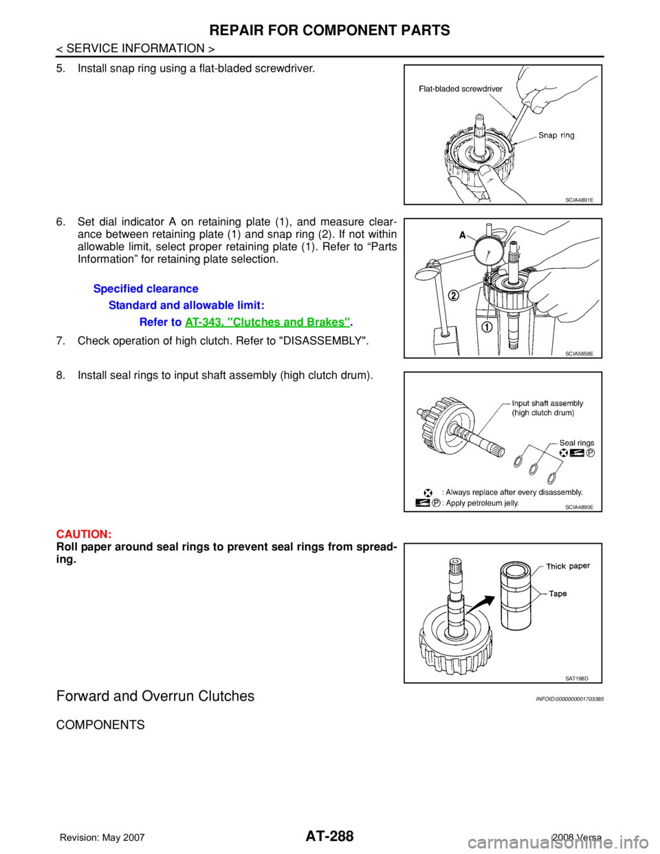
5. Install snap ring using a flat-bladed screwdriver.
6. Set dial indicator A on retaining plate (1), and measure clear-
ance between retaining plate (1) and snap ring (2). If not within
allowable limit, select proper retaining plate (1). Refer to “Parts
Information” for retaining plate selection.
7. Check operation of high clutch. Refer to "DISASSEMBLY".
8. Install seal rings to input shaft assembly (high clutch drum).
CAUTION:
Roll paper around seal rings to prevent seal rings from spread-
ing.
Forward and Overrun ClutchesINFOID:0000000001703385
COMPONENTS
SCIA4891E
Specified clearance
Standard and allowable limit:
Refer to AT-343, "
Clutches and Brakes".
SCIA5858E
SCIA4890E
SAT198D
Page 332 of 2771
AT-320
< SERVICE INFORMATION >
ASSEMBLY
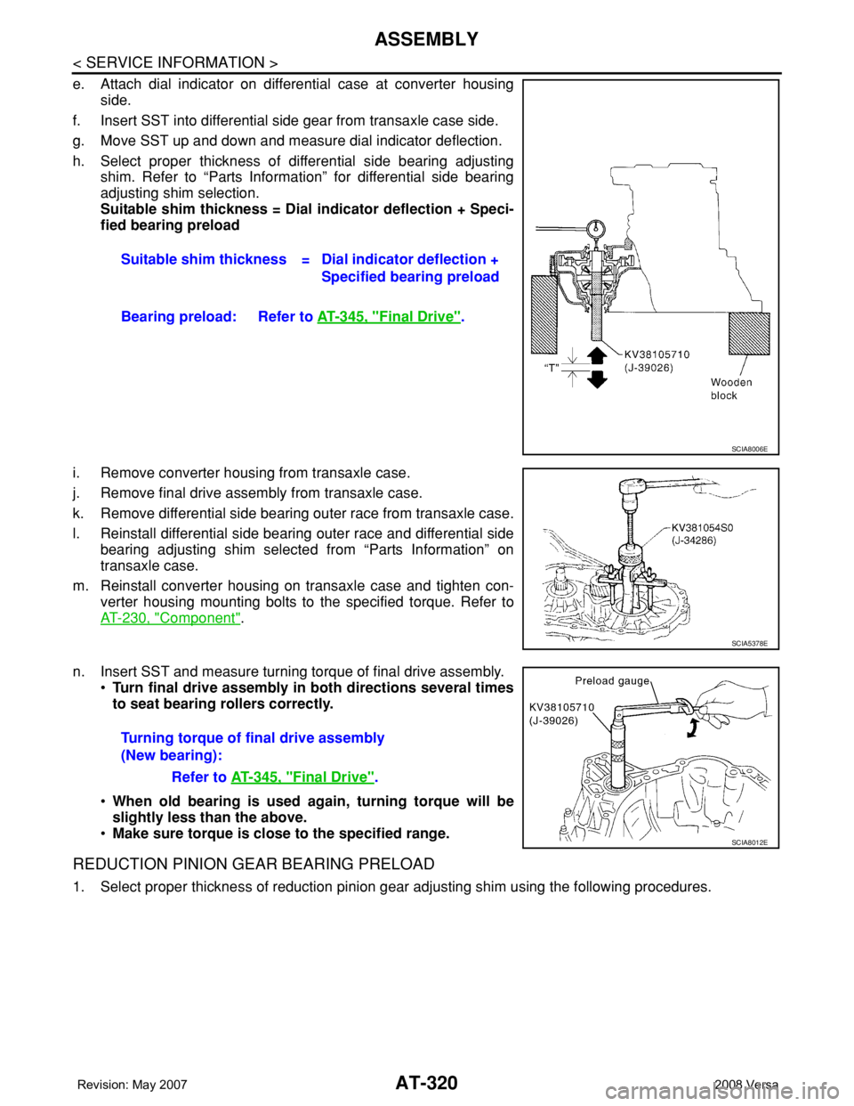
e. Attach dial indicator on differential case at converter housing
side.
f. Insert SST into differential side gear from transaxle case side.
g. Move SST up and down and measure dial indicator deflection.
h. Select proper thickness of differential side bearing adjusting
shim. Refer to “Parts Information” for differential side bearing
adjusting shim selection.
Suitable shim thickness = Dial indicator deflection + Speci-
fied bearing preload
i. Remove converter housing from transaxle case.
j. Remove final drive assembly from transaxle case.
k. Remove differential side bearing outer race from transaxle case.
l. Reinstall differential side bearing outer race and differential side
bearing adjusting shim selected from “Parts Information” on
transaxle case.
m. Reinstall converter housing on transaxle case and tighten con-
verter housing mounting bolts to the specified torque. Refer to
AT-230, "
Component".
n. Insert SST and measure turning torque of final drive assembly.
•Turn final drive assembly in both directions several times
to seat bearing rollers correctly.
•When old bearing is used again, turning torque will be
slightly less than the above.
•Make sure torque is close to the specified range.
REDUCTION PINION GEAR BEARING PRELOAD
1. Select proper thickness of reduction pinion gear adjusting shim using the following procedures.Suitable shim thickness = Dial indicator deflection +
Specified bearing preload
Bearing preload: Refer to AT-345, "
Final Drive".
SCIA8006E
SCIA5378E
Turning torque of final drive assembly
(New bearing):
Refer to AT-345, "
Final Drive".
SCIA8012E
Page 402 of 2771
TELEPHONE
AV-43
< SERVICE INFORMATION >
C
D
E
F
G
H
I
J
L
MA
B
AV
N
O
P
TELEPHONE
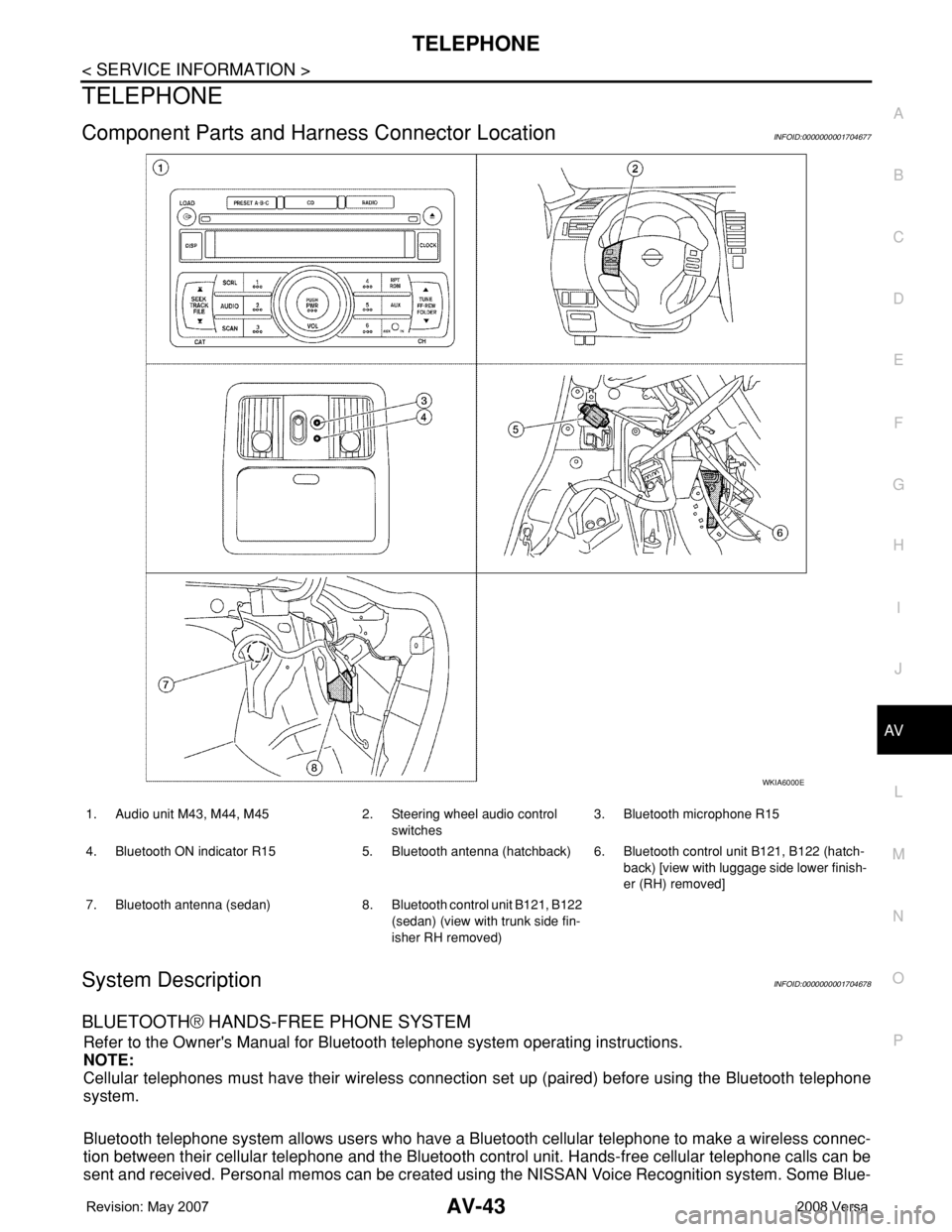
Component Parts and Harness Connector LocationINFOID:0000000001704677
System DescriptionINFOID:0000000001704678
BLUETOOTH® HANDS-FREE PHONE SYSTEM
Refer to the Owner's Manual for Bluetooth telephone system operating instructions.
NOTE:
Cellular telephones must have their wireless connection set up (paired) before using the Bluetooth telephone
system.
Bluetooth telephone system allows users who have a Bluetooth cellular telephone to make a wireless connec-
tion between their cellular telephone and the Bluetooth control unit. Hands-free cellular telephone calls can be
sent and received. Personal memos can be created using the NISSAN Voice Recognition system. Some Blue-
WKIA6000E
1. Audio unit M43, M44, M45 2. Steering wheel audio control
switches3. Bluetooth microphone R15
4. Bluetooth ON indicator R15 5. Bluetooth antenna (hatchback) 6. Bluetooth control unit B121, B122 (hatch-
back) [view with luggage side lower finish-
er (RH) removed]
7. Bluetooth antenna (sedan) 8. Bluetooth control unit B121, B122
(sedan) (view with trunk side fin-
isher RH removed)
Page 403 of 2771
AV-44
< SERVICE INFORMATION >
TELEPHONE
tooth cellular telephones may not be recognized by the Bluetooth control unit. When a cellular telephone or
the Bluetooth control unit is replaced, the telephone must be paired with the Bluetooth control unit. Different
cellular telephones may have different pairing procedures. Refer to the cellular telephone operating manual.
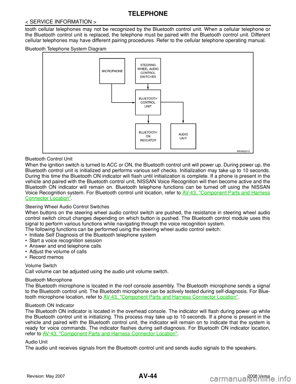
Bluetooth Telephone System Diagram
Bluetooth Control Unit
When the ignition switch is turned to ACC or ON, the Bluetooth control unit will power up. During power up, the
Bluetooth control unit is initialized and performs various self checks. Initialization may take up to 10 seconds.
During this time the Bluetooth ON indicator will flash until initialization is complete. If a phone is present in the
vehicle and paired with the Bluetooth control unit, NISSAN Voice Recognition will then become active and the
Bluetooth ON indicator will remain on. Bluetooth telephone functions can be turned off using the NISSAN
Voice Recognition system. For Bluetooth control unit location, refer to AV-43, "
Component Parts and Harness
Connector Location".
Steering Wheel Audio Control Switches
When buttons on the steering wheel audio control switch are pushed, the resistance in steering wheel audio
control switch circuit changes depending on which button is pushed. The Bluetooth control module uses this
signal to perform various functions while navigating through the voice recognition system.
The following functions can be performed using the steering wheel audio control switch:
• Initiate Self Diagnosis of the Bluetooth telephone system
• Start a voice recognition session
• Answer and end telephone calls
• Adjust the volume of calls
• Record memos
Volume Switch
Call volume can be adjusted using the audio unit volume switch.
Bluetooth Microphone
The Bluetooth microphone is located in the roof console assembly. The Bluetooth microphone sends a signal
to the Bluetooth control unit. The Bluetooth microphone can be actively tested during self-diagnosis. For Blue-
tooth microphone location, refer to AV-43, "
Component Parts and Harness Connector Location".
Bluetooth ON Indicator
The Bluetooth ON indicator is located in the overhead console. The indicator will flash during power up while
the Bluetooth control unit is initializing. This process may take up to 10 seconds. If a phone is present in the
vehicle and paired with the Bluetooth control unit, the indicator will remain on to indicate that the system is
ready for voice commands. The indicator flashes during self-diagnosis. For Bluetooth ON indicator location,
refer to AV-43, "
Component Parts and Harness Connector Location".
Audio Unit
The audio unit receives signals from the Bluetooth control unit and sends audio signals to the speakers.
WKIA6001E