Page 2657 of 2771

TROUBLE DIAGNOSIS
SRS-23
< SYMPTOM DIAGNOSIS >
C
D
E
F
G
I
J
K
L
MA
B
SRS
N
O
P
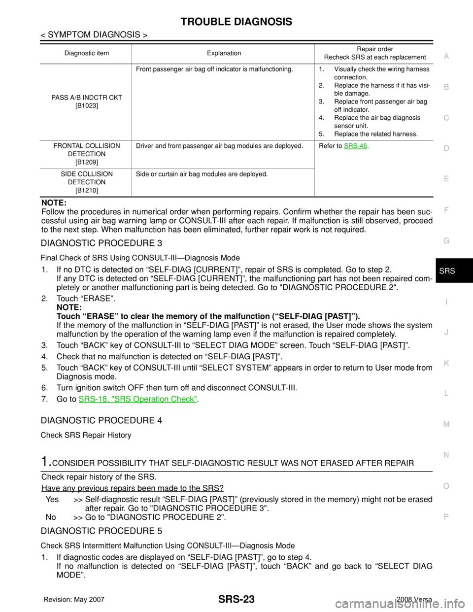
NOTE:
Follow the procedures in numerical order when performing repairs. Confirm whether the repair has been suc-
cessful using air bag warning lamp or CONSULT-III after each repair. If malfunction is still observed, proceed
to the next step. When malfunction has been eliminated, further repair work is not required.
DIAGNOSTIC PROCEDURE 3
Final Check of SRS Using CONSULT-III—Diagnosis Mode
1. If no DTC is detected on “SELF-DIAG [CURRENT]”, repair of SRS is completed. Go to step 2.
If any DTC is detected on “SELF-DIAG [CURRENT]”, the malfunctioning part has not been repaired com-
pletely or another malfunctioning part is being detected. Go to "DIAGNOSTIC PROCEDURE 2".
2. Touch “ERASE”.
NOTE:
Touch “ERASE” to clear the memory of the malfunction (“SELF-DIAG [PAST]”).
If the memory of the malfunction in “SELF-DIAG [PAST]” is not erased, the User mode shows the system
malfunction by the operation of the warning lamp even if the malfunction is repaired completely.
3. Touch “BACK” key of CONSULT-III to “SELECT DIAG MODE” screen. Touch “SELF-DIAG [PAST]”.
4. Check that no malfunction is detected on “SELF-DIAG [PAST]”.
5. Touch “BACK” key of CONSULT-III until “SELECT SYSTEM” appears in order to return to User mode from
Diagnosis mode.
6. Turn ignition switch OFF then turn off and disconnect CONSULT-III.
7. Go to SRS-18, "
SRS Operation Check".
DIAGNOSTIC PROCEDURE 4
Check SRS Repair History
1.CONSIDER POSSIBILITY THAT SELF-DIAGNOSTIC RESULT WAS NOT ERASED AFTER REPAIR
Check repair history of the SRS.
Have any previous repairs been made to the SRS?
Yes >> Self-diagnostic result “SELF-DIAG [PAST]” (previously stored in the memory) might not be erased
after repair. Go to "DIAGNOSTIC PROCEDURE 3".
No >> Go to "DIAGNOSTIC PROCEDURE 2".
DIAGNOSTIC PROCEDURE 5
Check SRS Intermittent Malfunction Using CONSULT-III—Diagnosis Mode
1. If diagnostic codes are displayed on “SELF-DIAG [PAST]”, go to step 4.
If no malfunction is detected on “SELF-DIAG [PAST]”, touch “BACK” and go back to “SELECT DIAG
MODE”.
PASS A/B INDCTR CKT
[B1023]Front passenger air bag off indicator is malfunctioning. 1. Visually check the wiring harness
connection.
2. Replace the harness if it has visi-
ble damage.
3. Replace front passenger air bag
off indicator.
4. Replace the air bag diagnosis
sensor unit.
5. Replace the related harness.
FRONTAL COLLISION
DETECTION
[B1209]Driver and front passenger air bag modules are deployed. Refer to SRS-46
.
SIDE COLLISION
DETECTION
[B1210]Side or curtain air bag modules are deployed. Diagnostic item ExplanationRepair order
Recheck SRS at each replacement
Page 2661 of 2771

TROUBLE DIAGNOSIS
SRS-27
< SYMPTOM DIAGNOSIS >
C
D
E
F
G
I
J
K
L
MA
B
SRS
N
O
P
NOTE:
Follow the procedures in numerical order when performing repairs. Confirm whether the repair has been suc-
cessful using air bag warning lamp or CONSULT-III after each repair. If malfunction is still observed, proceed
to the next step. When malfunction has been eliminated, further repair work is not required.
Trouble Diagnosis without CONSULT-IIIINFOID:0000000001703923
DIAGNOSTIC PROCEDURE 6
Inspect SRS Malfunction Using "AIR BAG" Warning Lamp—Diagnosis Mode
NOTE:
SRS will not enter Diagnosis mode if no malfunction is detected in User mode.
1. Turn ignition switch ON.
2. After “AIR BAG” warning lamp lights for 7 seconds, turn ignition switch OFF within 1 second.
3. Wait more than 3 seconds.
4. Repeat steps 1 to 3 two times.
5. Turn ignition switch ON.
SRS is now in Diagnosis mode.
"AIR BAG" warning lamp operates in Diagnosis mode according to the Warning Lamp Flash Code Chart:
OCCUPANT SENS C/U
[COMM FAIL]
[B1022]Communication between the occupant classification system
control unit and air bag diagnosis sensor unit is interrupted.1. Visually check the wiring harness
connection.
2. Replace the harness if it has visi-
ble damage.
3. Replace RH front seat cushion/
occupant classification system
control unit assembly.
4. Replace the air bag diagnosis
sensor unit.
5. Replace the related harness.
OCCUPANT SENS
[UNIT FAIL]
[B1018]Occupant classification sensor is malfunctioning. 1. Replace RH front seat cushion/
occupant classification system
control unit assembly.
BELT TENSION SENS
[UNIT FAIL]
[B1019]Belt tension sensor is malfunctioning. 1. Visually check the wiring harness
connection.
2. Replace the harness if it has visi-
ble damage.
3. Replace RH front seat belt as-
sembly.
4. Replace RH front seat cushion/
occupant classification system
control unit assembly.
PASS A/B INDCTR CKT
[B1023]Front passenger air bag off indicator is malfunctioning. 1. Visually check the wiring harness
connection.
2. Replace the harness if it has visi-
ble damage.
3. Replace front passenger air bag
off indicator.
4. Replace the air bag diagnosis
sensor unit.
5. Replace the related harness.
FRONTAL COLLISION
DETECTION
[B1209]Driver and front passenger air bag modules are deployed. Refer to SRS-46
.
SIDE COLLISION
DETECTION
[B1210]Side or curtain air bag modules are deployed. Diagnostic item ExplanationRepair order
Recheck SRS at each replacement
Page 2713 of 2771

ROAD WHEEL
WT-5
< SERVICE INFORMATION >
C
D
F
G
H
I
J
K
L
MA
B
WT
N
O
P
ROAD WHEEL
InspectionINFOID:0000000001703748
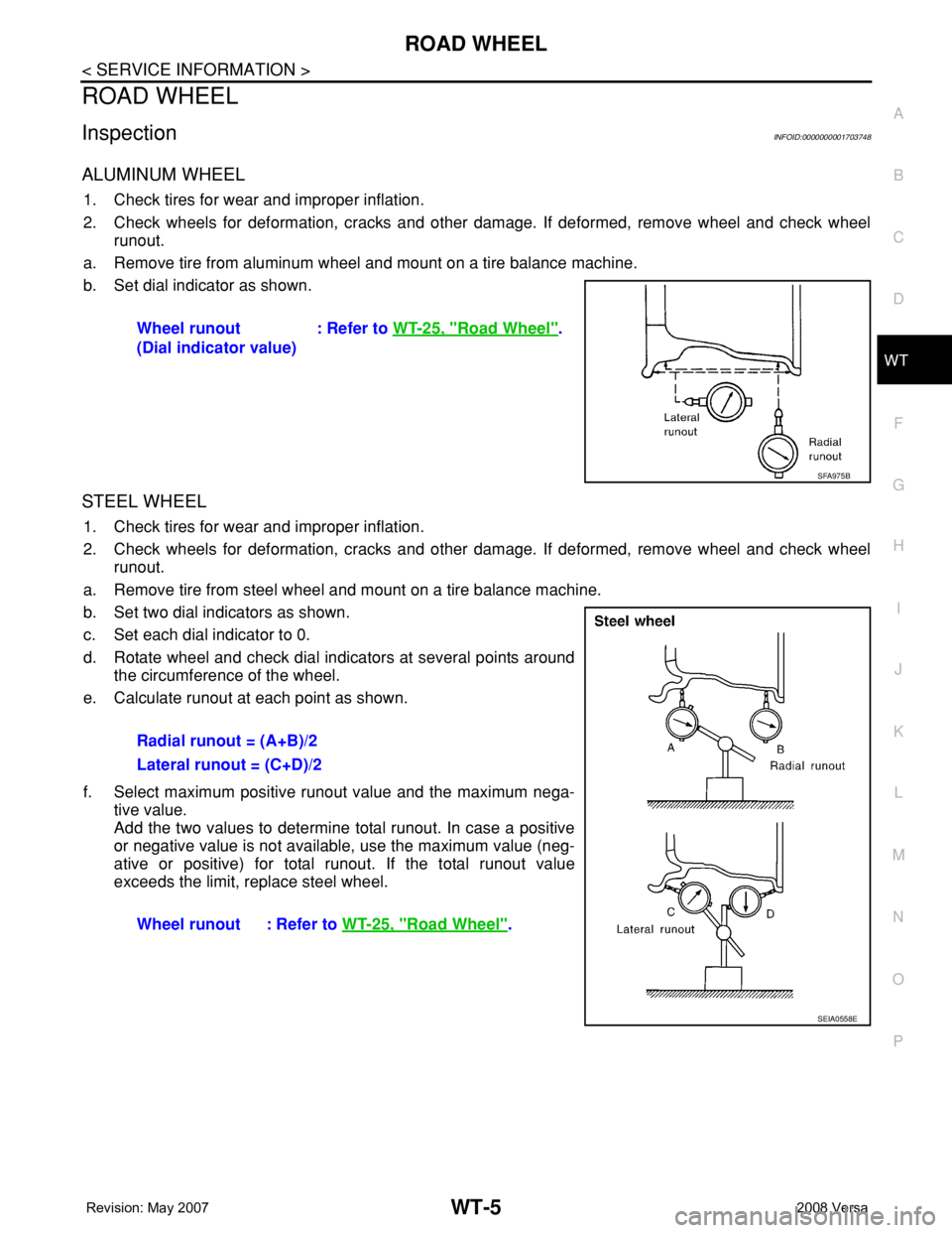
ALUMINUM WHEEL
1. Check tires for wear and improper inflation.
2. Check wheels for deformation, cracks and other damage. If deformed, remove wheel and check wheel
runout.
a. Remove tire from aluminum wheel and mount on a tire balance machine.
b. Set dial indicator as shown.
STEEL WHEEL
1. Check tires for wear and improper inflation.
2. Check wheels for deformation, cracks and other damage. If deformed, remove wheel and check wheel
runout.
a. Remove tire from steel wheel and mount on a tire balance machine.
b. Set two dial indicators as shown.
c. Set each dial indicator to 0.
d. Rotate wheel and check dial indicators at several points around
the circumference of the wheel.
e. Calculate runout at each point as shown.
f. Select maximum positive runout value and the maximum nega-
tive value.
Add the two values to determine total runout. In case a positive
or negative value is not available, use the maximum value (neg-
ative or positive) for total runout. If the total runout value
exceeds the limit, replace steel wheel.Wheel runout
(Dial indicator value): Refer to WT-25, "
Road Wheel".
SFA975B
Radial runout = (A+B)/2
Lateral runout = (C+D)/2
Wheel runout : Refer to WT-25, "
Road Wheel".
SEIA0558E
Page 2720 of 2771

WT-12
< SERVICE INFORMATION >
TROUBLE DIAGNOSES
6. Inflate all tires to proper pressure. Refer to WT-25, "Tire" .
Transmitter Wake Up OperationINFOID:0000000001703757
NOTE:
This procedure must be done after replacement of a low tire pressure warning transmitter or BCM.
New replacement transmitters are provided "asleep" and must first be "woken up" using Transmitter
Activation Tool J-45295 before ID registration can be performed.
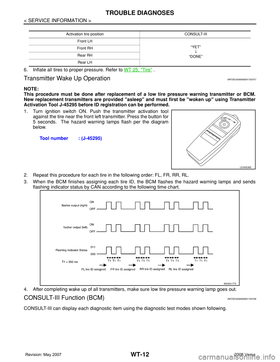
1. Turn ignition switch ON. Push the transmitter activation tool
against the tire near the front left transmitter. Press the button for
5 seconds. The hazard warning lamps flash per the diagram
below.
2. Repeat this procedure for each tire in the following order: FL, FR, RR, RL.
3. When the BCM finishes assigning each tire ID, the BCM flashes the hazard warning lamps and sends
flashing indicator status by CAN according to the following time chart.
4. After completing wake up of all transmitters, make sure low tire pressure warning lamp goes out.
CONSULT-III Function (BCM)INFOID:0000000001703758
CONSULT-III can display each diagnostic item using the diagnostic test modes shown following.
Activation tire position CONSULT-III
Front LH
“YET”
↓
“DONE” Front RH
Rear RH
Rear LH
Tool number : (J-45295)
LEIA0036E
WEIA0177E