2008 NISSAN TIIDA speedo
[x] Cancel search: speedoPage 1038 of 2771

COMBINATION METERS
DI-17
< SERVICE INFORMATION >
C
D
E
F
G
H
I
J
L
MA
B
DI
N
O
P
OK or NG
OK >> Check harness or connector between combination meter and vehicle speed sensor.
NG >> Replace vehicle speed sensor.
WITH CVT, WITHOUT ABS
1.CHECK COMBINATION METER INPUT SIGNAL
1. Start engine and select “METER/M&A” on CONSULT-III.
2. Using “SPEED METER” on “DATA MONITOR”, compare the value of “DATA MONITOR” with speedome-
ter pointer of combination meter.
OK or NG
OK >> Perform TCM self-diagnosis. Refer to CVT-47, "CONSULT-III Function (TRANSMISSION)" .
NG >> Replace combination meter. Refer to IP-11, "
Removal and Installation" .
Engine Speed Signal InspectionINFOID:0000000001704503
Symptom: Improper tachometer indication.
1.CHECK COMBINATION METER INPUT SIGNAL
1. Start engine and select “METER/M&A” on CONSULT-III.
2. Using “TACHO METER” on “DATA MONITOR”, compare the value of “DATA MONITOR” with tachometer
pointer of combination meter.
OK or NG
OK >> Perform ECM self-diagnosis. Refer to EC-109, "CONSULT-II Function (ENGINE)" .
NG >> Replace combination meter. Refer to IP-11, "
Removal and Installation" .
Fuel Level Sensor Signal InspectionINFOID:0000000001704504
Symptom:
• Improper fuel gauge indication.
• Low-fuel warning lamp indication is irregular.
NOTE:
The following symptoms do not indicate a malfunction.
• Depending on vehicle position or driving circumstance, the fuel level in the tank shifts and the indication may
fluctuate.
• If the vehicle is fueled with the ignition switch ON, the indication will update slowly.
• If the vehicle is tilted when the ignition switch is turned ON, fuel in the tank may flow to one direction result-
ing in a change of reading.
1.CHECK COMBINATION METER INPUT SIGNAL
1. Select “METER/M&A” on CONSULT-III.
2. Using “FUEL METER” on “DATA MONITOR”, compare the value of “DATA MONITOR” with fuel gauge
pointer of combination meter.
Te r m i n a l s
Resistance
value
(Approx.) (+) (–)
Component Terminal Component Terminal
Ve h i c l e
speed
sensor1Vehicle
speed
sensor2250Ω
Fuel gauge pointer Reference value of data monitor [lit.]
Full Approx. 49
3/4 Approx. 34
1/2 Approx. 22
1/4 Approx. 10
Empty Approx. 4
Page 1195 of 2771

TROUBLE DIAGNOSIS
EC-121
< SERVICE INFORMATION >
C
D
E
F
G
H
I
J
K
L
MA
EC
N
P O
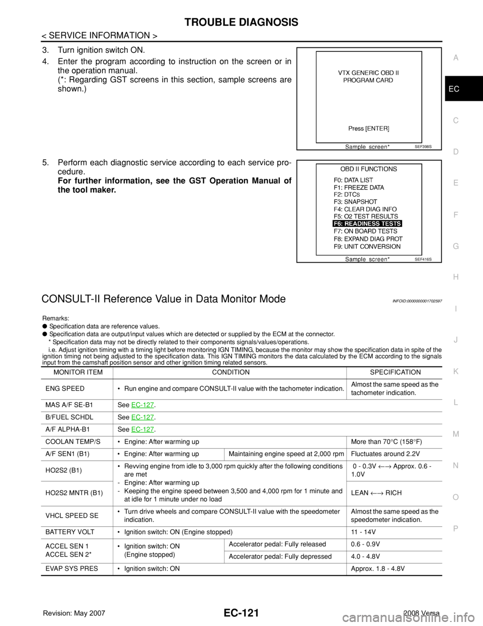
3. Turn ignition switch ON.
4. Enter the program according to instruction on the screen or in
the operation manual.
(*: Regarding GST screens in this section, sample screens are
shown.)
5. Perform each diagnostic service according to each service pro-
cedure.
For further information, see the GST Operation Manual of
the tool maker.
CONSULT-II Reference Value in Data Monitor ModeINFOID:0000000001702597
Remarks:
● Specification data are reference values.
● Specification data are output/input values which are detected or supplied by the ECM at the connector.
* Specification data may not be directly related to their components signals/values/operations.
i.e. Adjust ignition timing with a timing light before monitoring IGN TIMING, because the monitor may show the specification data in spite of the
ignition timing not being adjusted to the specification data. This IGN TIMING monitors the data calculated by the ECM according to the signals
input from the camshaft position sensor and other ignition timing related sensors.
SEF398S
SEF416S
MONITOR ITEM CONDITION SPECIFICATION
ENG SPEED • Run engine and compare CONSULT-II value with the tachometer indication.Almost the same speed as the
tachometer indication.
MAS A/F SE-B1 See EC-127
.
B/FUEL SCHDL See EC-127
.
A/F ALPHA-B1 See EC-127
.
COOLAN TEMP/S • Engine: After warming up More than 70°C (158°F)
A/F SEN1 (B1) • Engine: After warming up Maintaining engine speed at 2,000 rpm Fluctuates around 2.2V
HO2S2 (B1)• Revving engine from idle to 3,000 rpm quickly after the following conditions
are met
- Engine: After warming up
- Keeping the engine speed between 3,500 and 4,000 rpm for 1 minute and
at idle for 1 minute under no load 0 - 0.3V ←→ Approx. 0.6 -
1.0V
HO2S2 MNTR (B1)LEAN ←→ RICH
VHCL SPEED SE• Turn drive wheels and compare CONSULT-II value with the speedometer
indication.Almost the same speed as the
speedometer indication.
BATTERY VOLT • Ignition switch: ON (Engine stopped) 11 - 14V
ACCEL SEN 1
ACCEL SEN 2*• Ignition switch: ON
(Engine stopped)Accelerator pedal: Fully released 0.6 - 0.9V
Accelerator pedal: Fully depressed 4.0 - 4.8V
EVAP SYS PRES • Ignition switch: ON Approx. 1.8 - 4.8V
Page 1197 of 2771

TROUBLE DIAGNOSIS
EC-123
< SERVICE INFORMATION >
C
D
E
F
G
H
I
J
K
L
MA
EC
N
P O
INT/V SOL (B1)• Engine: After warming up
• Air conditioner switch: OFF
• Shift lever: P or N (A/T, CVT),
Neutral (M/T)
•No loadIdle 0% - 2%
When revving engine up to 2,000 rpm
quicklyApprox. 0% - 90%
AIR COND RLY• Engine: After warming up, idle the
engineAir conditioner switch: OFF OFF
Air conditioner switch: ON
(Compressor operates)ON
FUEL PUMP RLY• For 1 second after turning ignition switch ON
• Engine running or crankingON
• Except above conditions OFF
VENT CONT/V • Ignition switch: ON OFF
THRTL RELAY • Ignition switch: ON ON
COOLING FAN• Engine: After warming up, idle the
engine
• Air conditioner switch: OFFEngine coolant temperature: 97°C
(207°F) or lessOFF
Engine coolant temperature: Between
98°C (208°F) and 99°C (210°F)LOW
Engine coolant temperature: 100°C
(212°F) or moreHIGH
HO2S2 HTR (B1)• Below 3,600 rpm after the following conditions are met.
- Engine: After warming up
- Keeping the engine speed between 3,500 and 4,000 rpm for 1 minute and
at idle for 1 minute under no loadON
• Engine speed: Above 3,600 rpm OFF
I/P PULLY SPD • Vehicle speed: More than 20 km/h (12 MPH)Almost the same speed as the
tachometer indication
VEHICLE SPEED• Turn drive wheels and compare CONSULT-II value with the speedometer
indication.Almost the same speed as the
speedometer indication
TRVL AFTER MIL • Ignition switch: ONVehicle has traveled after MIL has
turned ON.0 - 65,535 km
(0 - 40,723 mile)
A/F S1 HTR (B1)• Engine: After warming up, idle the engine
(More than 140 seconds after starting engine.)4 - 100%
AC PRESS SEN• Engine: Idle
• Air conditioner switch: ON (Compressor operates)1.0 - 4.0V
VHCL SPEED SE• Turn drive wheels and compare speedometer indication with the CONSULT-
II value.Almost the same speed as the
speedometer indication
SET VHCL SPD • Engine: Running ASCD: OperatingThe preset vehicle speed is
displayed.
MAIN SW • Ignition switch: ONMAIN switch: Pressed ON
MAIN switch: Released OFF
CANCEL SW • Ignition switch: ONCANCEL switch: Pressed ON
CANCEL switch: Released OFF
RESUME/ACC SW • Ignition switch: ONRESUME/ACCELERATE switch:
PressedON
RESUME/ACCELERATE switch: Re-
leased
OFF
SET SW • Ignition switch: ONSET/COAST switch: Pressed ON
SET/COAST switch: Released OFF MONITOR ITEM CONDITION SPECIFICATION
Page 2002 of 2771
![NISSAN TIIDA 2008 Service Repair Manual TROUBLE DIAGNOSIS
LAN-11
< FUNCTION DIAGNOSIS >[CAN FUNDAMENTAL]
C
D
E
F
G
H
I
J
L
MA
B
LAN
N
O
P Example: Main Line Between Data Link Connector and ABS Actuator and Electric Unit (Control Unit) Open NISSAN TIIDA 2008 Service Repair Manual TROUBLE DIAGNOSIS
LAN-11
< FUNCTION DIAGNOSIS >[CAN FUNDAMENTAL]
C
D
E
F
G
H
I
J
L
MA
B
LAN
N
O
P Example: Main Line Between Data Link Connector and ABS Actuator and Electric Unit (Control Unit) Open](/manual-img/5/57399/w960_57399-2001.png)
TROUBLE DIAGNOSIS
LAN-11
< FUNCTION DIAGNOSIS >[CAN FUNDAMENTAL]
C
D
E
F
G
H
I
J
L
MA
B
LAN
N
O
P Example: Main Line Between Data Link Connector and ABS Actuator and Electric Unit (Control Unit) Open Circuit
Example: CAN-H, CAN-L Harness Short Circuit
SKIB8740E
Unit name Symptom
ECM Engine torque limiting is affected, and shift harshness increases.
BCM• Reverse warning chime does not sound.
• The front wiper moves under continuous operation mode even though the front wip-
er switch being in the intermittent position.
EPS control unit The steering effort increases.
Combination meter• The shift position indicator and OD OFF indicator turn OFF.
• The speedometer is inoperative.
• The odo/trip meter stops.
ABS actuator and electric unit (control unit) Normal operation.
TCM No impact on operation.
IPDM E/RWhen the ignition switch is ON,
• The headlamps (Lo) turn ON.
• The cooling fan continues to rotate.
SKIB8741E
Page 2003 of 2771
![NISSAN TIIDA 2008 Service Repair Manual LAN-12
< FUNCTION DIAGNOSIS >[CAN FUNDAMENTAL]
TROUBLE DIAGNOSIS
CAN Diagnosis with CONSULT-III
INFOID:0000000001711207
CAN diagnosis on CONSULT-III extracts the root cause by receiving the following NISSAN TIIDA 2008 Service Repair Manual LAN-12
< FUNCTION DIAGNOSIS >[CAN FUNDAMENTAL]
TROUBLE DIAGNOSIS
CAN Diagnosis with CONSULT-III
INFOID:0000000001711207
CAN diagnosis on CONSULT-III extracts the root cause by receiving the following](/manual-img/5/57399/w960_57399-2002.png)
LAN-12
< FUNCTION DIAGNOSIS >[CAN FUNDAMENTAL]
TROUBLE DIAGNOSIS
CAN Diagnosis with CONSULT-III
INFOID:0000000001711207
CAN diagnosis on CONSULT-III extracts the root cause by receiving the following information.
• Response to the system call
• Control unit diagnosis information
• Self-diagnosis
• CAN diagnostic support monitor
Self-DiagnosisINFOID:0000000001711208
CAN Diagnostic Support MonitorINFOID:0000000001711209
MONITOR ITEM (CONSULT-III)
Unit name Symptom
ECM• Engine torque limiting is affected, and shift harshness increases.
• Engine speed drops.
BCM• Reverse warning chime does not sound.
• The front wiper moves under continuous operation mode even though the front
wiper switch being in the intermittent position.
• The room lamp does not turn ON.
• The engine does not start (if an error or malfunction occurs while turning the igni-
tion switch OFF.)
• The steering lock does not release (if an error or malfunction occurs while turning
the ignition switch OFF.)
EPS control unit The steering effort increases.
Combination meter• The tachometer and the speedometer do not move.
• Warning lamps turn ON.
• Indicator lamps do not turn ON.
ABS actuator and electric unit (control unit) Normal operation.
TCM No impact on operation.
IPDM E/RWhen the ignition switch is ON,
• The headlamps (Lo) turn ON.
• The cooling fan continues to rotate.
DTCSelf-diagnosis item
(CONSULT-III indication)DTC detection condition Inspection/Action
U1000 CAN COMM CIRCUITWhen ECM is not transmitting or receiving CAN
communication signal of OBD (emission-related
diagnosis) for 2 seconds or more.
Start the inspection. Re-
fer to the applicable sec-
tion of the indicated
control unit. When a control unit (except for ECM) is not
transmitting or receiving CAN communication
signal for 2 seconds or more.
U1001 CAN COMM CIRCUITWhen ECM is not transmitting or receiving CAN
communication signal other than OBD (emis-
sion-related diagnosis) for 2 seconds or more.
U1002 SYSTEM COMMWhen a control unit is not transmitting or receiv-
ing CAN communication signal for 2 seconds or
less.
U1010 CONTROL UNIT [CAN]When an error is detected during the initial diag-
nosis for CAN controller of each control unit.Replace the control unit
indicating “U1010”.
Page 2311 of 2771

TRANSAXLE ASSEMBLY
MT-23
< SERVICE INFORMATION >
D
E
F
G
H
I
J
K
L
MA
B
MT
N
O
P
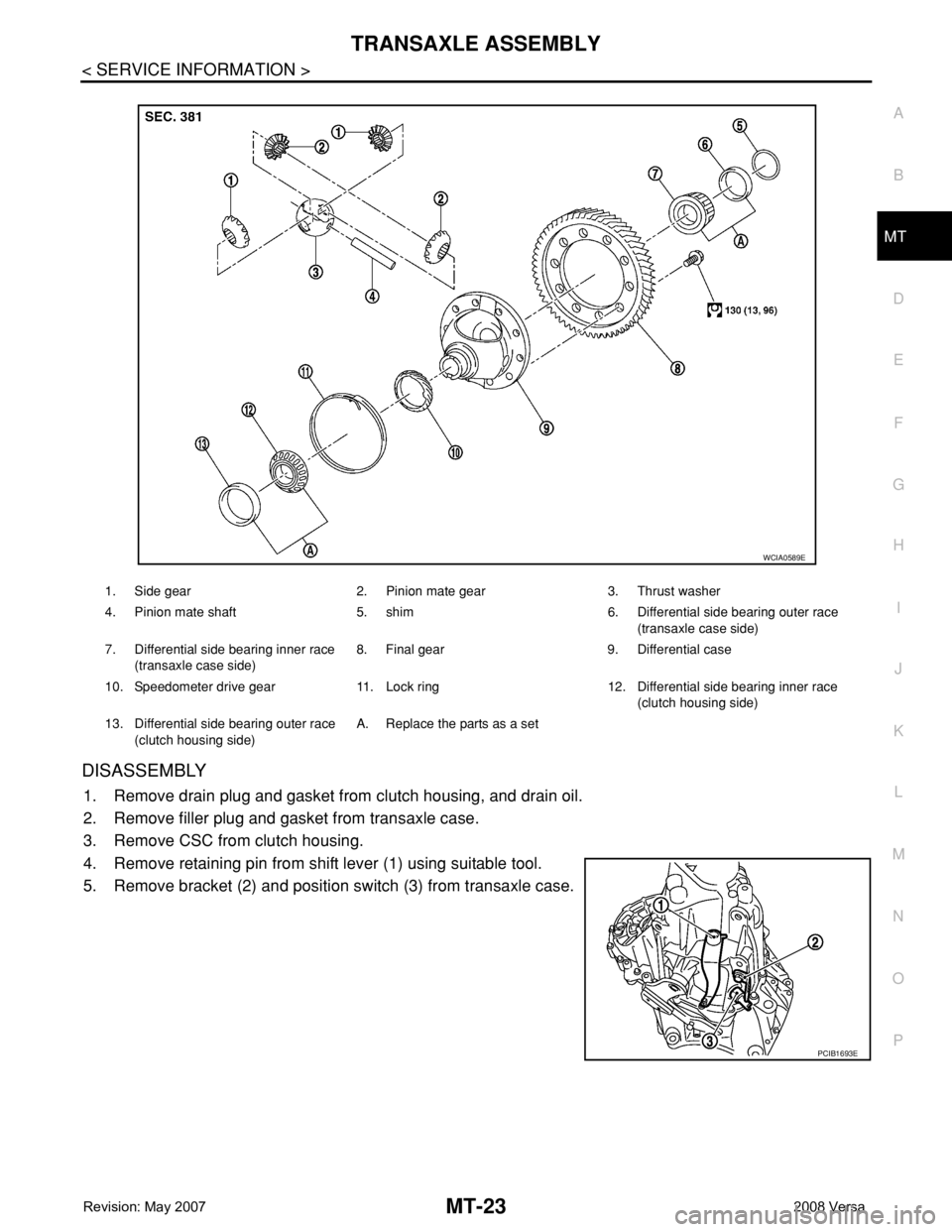
DISASSEMBLY
1. Remove drain plug and gasket from clutch housing, and drain oil.
2. Remove filler plug and gasket from transaxle case.
3. Remove CSC from clutch housing.
4. Remove retaining pin from shift lever (1) using suitable tool.
5. Remove bracket (2) and position switch (3) from transaxle case.
1. Side gear 2. Pinion mate gear 3. Thrust washer
4. Pinion mate shaft 5. shim 6. Differential side bearing outer race
(transaxle case side)
7. Differential side bearing inner race
(transaxle case side)8. Final gear 9. Differential case
10. Speedometer drive gear 11. Lock ring 12. Differential side bearing inner race
(clutch housing side)
13. Differential side bearing outer race
(clutch housing side)A. Replace the parts as a set
WCIA0589E
PCIB1693E
Page 2334 of 2771

MT-46
< SERVICE INFORMATION >
FINAL DRIVE
FINAL DRIVE
Disassembly and AssemblyINFOID:0000000001703146
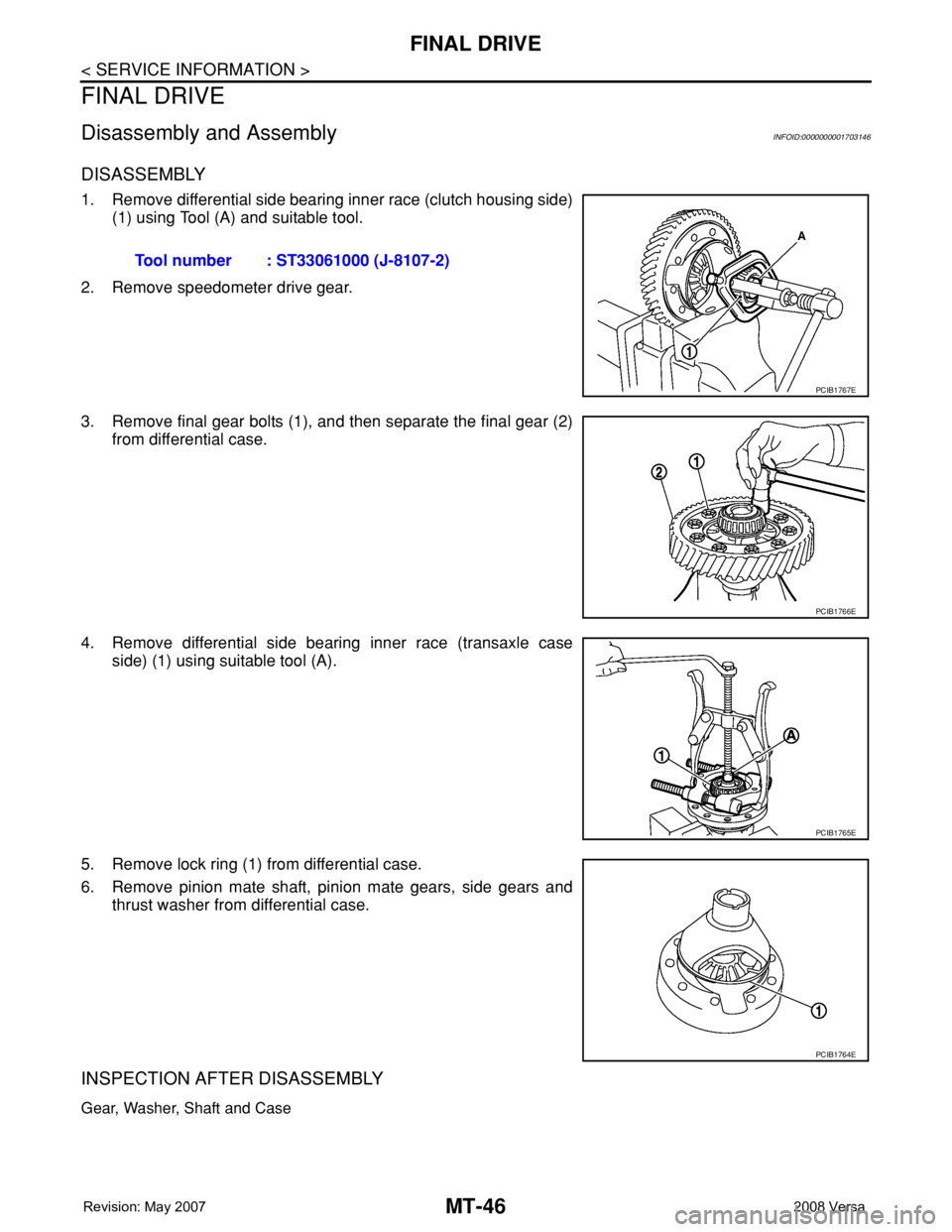
DISASSEMBLY
1. Remove differential side bearing inner race (clutch housing side)
(1) using Tool (A) and suitable tool.
2. Remove speedometer drive gear.
3. Remove final gear bolts (1), and then separate the final gear (2)
from differential case.
4. Remove differential side bearing inner race (transaxle case
side) (1) using suitable tool (A).
5. Remove lock ring (1) from differential case.
6. Remove pinion mate shaft, pinion mate gears, side gears and
thrust washer from differential case.
INSPECTION AFTER DISASSEMBLY
Gear, Washer, Shaft and Case
Tool number : ST33061000 (J-8107-2)
PCIB1767E
PCIB1766E
PCIB1765E
PCIB1764E
Page 2335 of 2771

FINAL DRIVE
MT-47
< SERVICE INFORMATION >
D
E
F
G
H
I
J
K
L
MA
B
MT
N
O
P
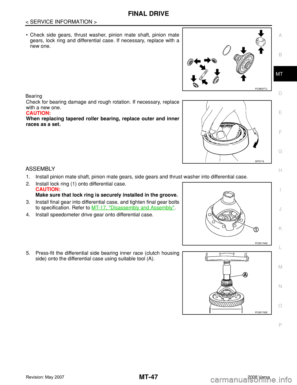
• Check side gears, thrust washer, pinion mate shaft, pinion mate
gears, lock ring and differential case. If necessary, replace with a
new one.
Bearing
Check for bearing damage and rough rotation. If necessary, replace
with a new one.
CAUTION:
When replacing tapered roller bearing, replace outer and inner
races as a set.
ASSEMBLY
1. Install pinion mate shaft, pinion mate gears, side gears and thrust washer into differential case.
2. Install lock ring (1) onto differential case.
CAUTION:
Make sure that lock ring is securely installed in the groove.
3. Install final gear into differential case, and tighten final gear bolts
to specification. Refer to MT-17, "
Disassembly and Assembly".
4. Install speedometer drive gear onto differential case.
5. Press-fit the differential side bearing inner race (clutch housing
side) onto the differential case using suitable tool (A).
PCIB0977J
SPD715
PCIB1764E
PCIB1762E